F5300LINKS2450LINKS 2450 Long Range RF Transmitter
Tyco Safety Products Canada Ltd.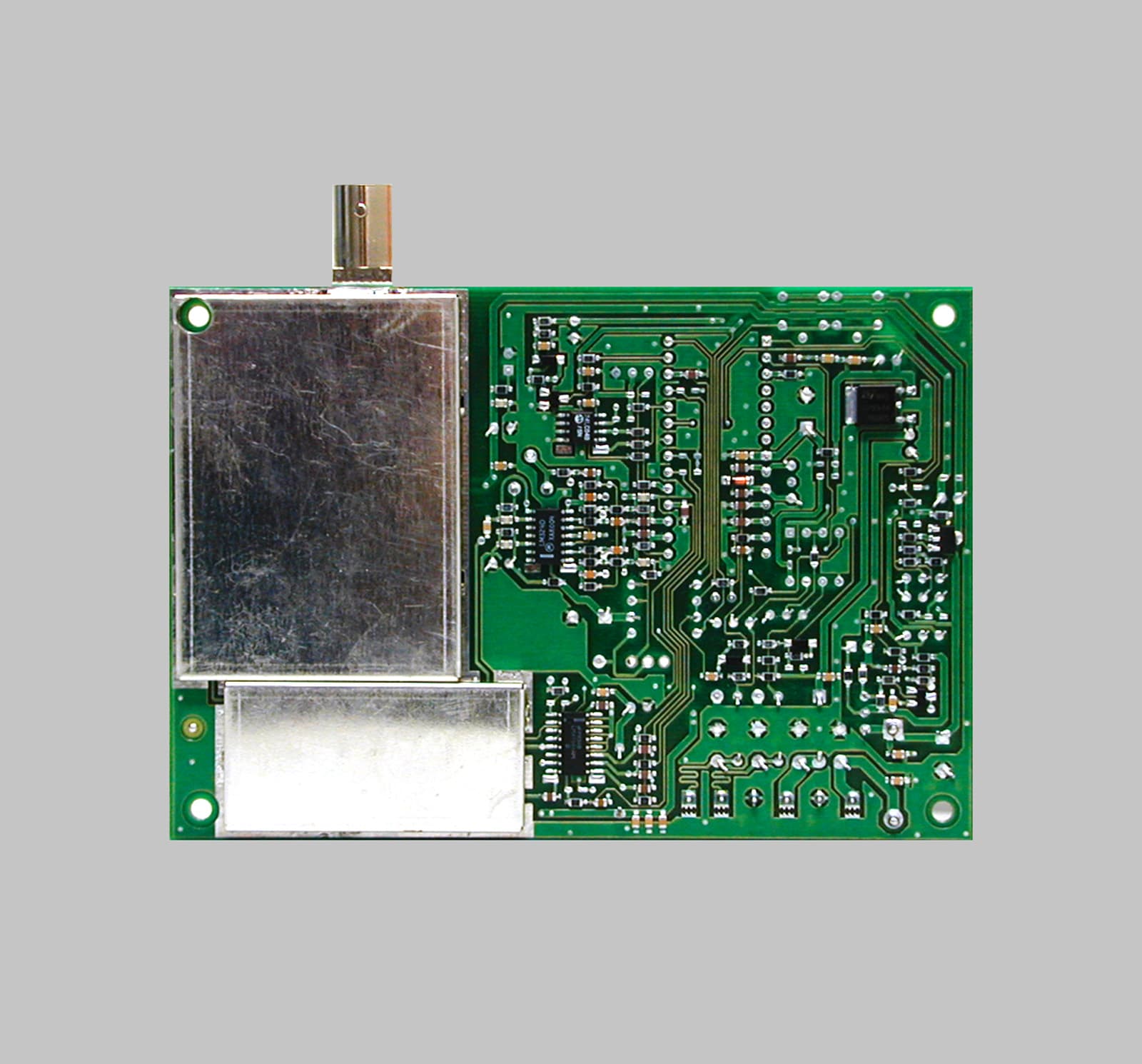
Click to zoom
Application Details
- Equipment Class
- TNB - Licensed Non-Broadcast Station Transmitter
- Date of Grant
- Jan 31, 2001
- Application Purpose
- Original Equipment
- Date of Application
- Nov 29, 2000
- Equipment Note
- LINKS 2450 Long Range RF Transmitter
- Frequency Range
- 450.00000000 - 470.00000000
- Country
- Canada
Documents & Files
Document Text
Text extracted from the exhibit documents filed with the FCC. Open a document above to read the original.
Users Manual
INSTALLATION MANUAL Version 1.2 • W A R N I N G • Please refer to the System Installation Manual for information on limitations regarding product use and function and information on the limitations as to liability of the manufacturer. Long Range RF Transmitter © 2000 SG Wireless Communications 401 Magnetic Drive, Units #24-28 Downsview, Ontario, Canada M3J 3H9 29003619 R001 How to Contact Us: Sales For information about additional products, please call our sales number:1-888-623-7873, fax us at 1-416-665-4222 or e-mail us at [email protected] SupportIf you have questions or problems when using Sur-Gard products, you can call technicalsupport. If you are within the United States, Puerto Rico, the U.S. Virgin Islands or Canada,you can get support by dialing 1-888-623-7873 ext.1. If you are outside these areas,please call (416) 665- 0051 ext.1, or e-mail us at [email protected]. InternetVisit our Sur-Gard WWW site. You can search the Sur-Gard technical information databaseand read about our new productsas well as send us your questions on-line. Our World Wide Web address is http://www.sur-gard.com. TABLE OF CONTENTS Section 1: Introduction 1 1.1 Specifications ........................................................................................ 1 1.2 Antenna ................................................................................................. 2 Section 2: Installing the Links2450 3 2.1 Unpacking the LINKS2450 .................................................................... 3 2.2 Select a Mounting Location .................................................................. 3 2.3 Connect a Power Supply ....................................................................... 3 2.4 Mount and Wire the LINKS2450 ........................................................... 4Diagram 2-1: Hook-up For PC5010, PC5015, PC1555/1565,PC1575/1580 or PC580/585 Panels .................................................... 5Diagram 2-2: Hook-up for PC4010/4020 v3.0 Panels ........................... 6 Section 3: Programming the LINKS2450 7 3.1 Programming a LINKS2450 Connected to a PC5015, PC5010,PC1575/1580, PC1555/1565 PC580/585 Panel ................................... 7 3.2 Programming a LINKS2450 for Use with aPC4010/PC4020 v3.0 or higher panel. ................................................ 8Diagram 3-1: Connecting the LINKS2450 to a PC2550RK Keypad ........ 8 Section 4: Programming Descriptions 10 [01] Module Configuration ......................................................................... 10 [10] LINKS 2450 Account Code ................................................................. 10 [20] Maintenance Alarms and Restoral Reporting Codes ......................... 10 [30] Call Direction Options (PC5015, PC5010, PC1575/1580,PC1555/1565 and PC580/585 panels only) ...................................... 10 [81] Miscellaneous Alarm Reporting Codes (PC1575/1580 panel only) ..... 11 [82] Miscellaneous Restoral Reporting Codes (PC1575/1580 panel only) .... 11 [83] Miscellaneous Alarm Reporting Codes(PC1555/1565 v2.0 panel only) .......................................................... 11 Section 5: Testing the LINKS2450 12 5.1 Performing a LINKS Test Transmission .............................................. 12 5.2 “On Air” Indication ............................................................................... 12 5.3 Troubleshooting ................................................................................... 12 5.4 Testing Tools ........................................................................................ 12 5.5 Periodic Test Transmission .................................................................. 12 Section 6: Reset LINKS2450 Programming to Factory Default 13 6.1 Reset the LINKS2450 on a PC1575/1580 Panel ................................ 13 6.2 Reset the LINKS2450 on a PC5015 v2.2, PC5010 v2.0,PC1555/1565 or PC580/585 Panel .................................................... 13 6.3 Perform a Hardware Reset (All panels) ............................................. 13 Programming Worksheets 14 i Limited WarrantySG Wireless Communications warrants that for a period of twelve months from the date of purchase,the product shall be free from defects in materials and workmanship under normal use and that infulfillment of any breech of such warranty, SG Wireless Communications shall, at its option, repairor replace the defective equipment upon return of the equipment to its repair depot. This warrantyapplies only to defects in parts and workmanship and not to damage incurred in shipping orhandling, or damage due to causes beyond the control of SG Wireless Communications, such aslightning, excessive voltage, mechanical shock, water damage, or damage arising out of abuse,alteration or improper application of the equipment.The foregoing warranty shall apply only to the original buyer, and is and shall be in lieu of any andall other warranties, whether expressed or implied and of all other obligations or liabilities on the partof SG Wireless Communications. SG Wireless Communications neither assumes, nor authorizesany other person purporting to act on its behalf to modify or to change this warranty, nor to assumefor it any other warranty or liability concerning this product.In no event shall SG Wireless Communications be liable for any direct or indirect or consequentialdamages, loss of anticipated profits, loss of time or any other losses incurred by the buyer inconnection with the purchase, installation or operation or failure of this product.WARNING: SG Wireless Communications recommends that the entire system be completely tested on a regular basis. However, despite frequent testing, and due to but not limited to,criminal tampering or electrical disruption, it is possible for this product to fail to performas expected. ii NOTES: NOTES: 1 INTRODUCTION Section 1 The LINKS2450 transmits alarm system information over a long-range radionetwork. It may be…
Text truncated - open the document above for the full version.
Attestation Statements
November 23, 2000 Office of Engineering & Technology Federal Communications Commission Washington, D.C. 20554 Subject:Request for continuous confidentiality of technical information per sections 0.459 and 0.457 (d) (2) ( I) of CFR 47. FCC ID:F5300LINKS2450 Dear Sir or Madam: Digital Security Controls Canada Ltd. is hereby filing this request for continuous confidentiality of the specified items submitted with the application for certification ( Form731 ) with proposed identifier F5300LINKS2450. The technical documentation for which continuous confidentiality is sought is: (1) Schematic diagrams: This technical documentation is a part of the material supporting the Form 731 application for certification, which this request for confidentiality accompanies. The schematic diagrams disclose proprietary information and technical data which Digital Security Controls Ltd. would guard from its competitors and would not make available to the public. This proprietary information constitutes a trade secret and is not a part of the product documentation that would be made available to the customers of Digital Security Controls Ltd. It would be potentially injurious to Digital Security Controls Ltd. and to its investment in the development of this innovative proprietary product to make available for public disclosure the trade secret technical information specified in this request. If there are any questions about this request for continuous confidentiality regarding trade secrets and proprietary information embodied in the technical documentation filed in support of this Form 731 application, then please contact me via our toll-free telephone number. Yours truly, Kevin Harris Approval Services Manager 905-760-3000 Ext. 2378 Email: [email protected]
ID Label/Location Info
FCC/IC Labelling for LINKS2450 File: [LINKS2450_fcc+ic_18004329_r002.cdr] September 27, 2000 SIDE OF THE UNIT SHOWING PLACEMENT OF LABEL (ACTUAL SIZE) DASHED LINE INDICATES CUT EDGE OF LABEL LABEL TO BE PRINTED ON CLEAR SELF-ADHESIVE MATERIAL LABEL SHOWN 200% ACTUAL SIZE 60 mm 13 mm Model: LINKS2450 F5300LINKS2450 Canada: XXX XXX XXXMADE IN CANADA 18004329 R002 DIGITAL SECURITY CONTROLS LTD. IC: RSS/CNR210 This device complies with Part 15 of the FCC rules. Operation is subject to the following two conditions: (1) this device may not cause harmful interference, and (2) this device must accept any interference received, including interference that may cause undesired operation. FCC ID: Model: LINKS2450 F5300LINKS2450 Canada: XXX XXX XXXMADE IN CANADA 18004329 R002 DIGITAL SECURITY CONTROLS LTD. IC: RSS/CNR210 This device complies with Part 15 of the FCC rules. Operation is subject to the following two conditions: (1) this device may not cause harmful interference, and (2) this device must accept any interference received, including interference that may cause undesired operation. FCC ID: Digital Security Controls Ltd. ISO9001 Registered 3301 Langstaff Road, Concord Ontario, Canada L4K 4L2 Phone: 905-760-3000 Toll Free: 1-888-888-7838 Fax: 905-760-3030 ®
Operational Description
CIRCUIT DESCRIPTION Device: LINKS 2450 Model: LINKS 2450 ESI Identifier: Schematic Diagram: Description: The Links 2450 Rev03 is a FM Narrowband transmitter operating through the frequency band of 450 to 470 MHz and has an output of 2W. The operation of the transmitter is microprocessor controlled and it interfaces with a number of the company’s control panels. It is meant operate as a remote one-way radio link to a central security monitoring station. The Links 2450 consists of two main circuit sections. A control section with a microprocessor based digital logic and the RF transmitter. The control section receives information from the control panel and in turn operates the transmitter to transmit the appropriate message(s). It uses a Varitech format for encoding the message and produces two tones 1070 and 1270 Hz to modulate the transmitter carrier at the selected carrier frequency. The transmitter consists of, a Voltage Controlled Oscillator ((VCO) as the carrier source), a Phase lock Loop (PLL) system, a buffer stage, a pre - driver stage and a final power amplifier stage. The reference frequency for the PLL is derived from a temperature controlled crystal oscillator (TCXO) The VCO is turned on by the microprocessor and is locked on to the desired transmit frequency via the PLL. The PLL sends a “lock detect” signal to the microprocessor which then turns on the Pre-driver and the Power Amplifier stages. A settling time of approximately 15 ms is allowed to elapse before the microprocessor begins to shift out the data that is used to modulate the carrier. The power amplifier, which has an output power of 2 W, is connected to an antenna through a matching compensation network. The signal from the power amplifier is transmitted via the antenna to the receiver where it is decoded and acted upon.
Operational Description
The LINKS 2450 is intended to operate within the band of 450 to 470 MHz inclusive. However, the end user will only be able to operate at a fixed frequency. The end user informs us of the Frequency that they will operate at(which they are licensed for) and that frequency is preprogrammed at our Factory. For example we may have a customer who is licensed to operate at 456.015 MHz, We program this frequency into the units that are to be shipped to that specific customer. Therefore to the customer it is a single frequency operating device. Please note that at the time of our initial application we were advised to center our tests at 455 MHz. I have included a document that shows the MPE calculation of our safe distance requirement. Please note that we had rounded off our calculated value to a convenient figure that would cover our band of operation and also add a margin to the calculated distance. Hope this information helped. Please contact us if any further explanation is required. Thank you and Best Regards, Sherwyn Welshman Manager Wireless Group Sensors and Wireless Division
RF Exposure Info
TABLE OF CONTENTS Section 1: Introduction1 1.1Specifications...........................................................................................1 1.2Antenna.....................................................................................................2 Section 2: Installing the Links24503 2.1Unpacking the LINKS2450......................................................................3 2.2Select a Mounting Location.....................................................................3 2.3Connect a Power Supply.........................................................................3 2.4Mount and Wire the LINKS2450.............................................................4 Diagram 2-1: Hook-up For PC5010, PC5015, PC1555/1565, PC1575/1580 or PC580/585 Panels......................................................5 Diagram 2-2: Hook-up for PC4010/4020 v3.0 Panels............................6 Section 3: Programming the LINKS24507 3.1Programming a LINKS2450 Connected to a PC5015, PC5010, PC1575/1580, PC1555/1565 PC580/585 Panel....................................7 3.2Programming a LINKS2450 for Use with a PC4010/PC4020 v3.0 or higher panel...................................................8 Diagram 3-1: Connecting the LINKS2450 to a PC2550RK Keypad........8 Section 4: Programming Descriptions10 [01]Module Configuration............................................................................10 [10]LINKS 2450 Account Code...................................................................10 [20]Maintenance Alarms and Restoral Reporting Codes..........................10 [30]Call Direction Options (PC5015, PC5010, PC1575/1580, PC1555/1565 and PC580/585 panels only)........................................10 [81]Miscellaneous Alarm Reporting Codes (PC1575/1580 panel only)....11 [82]Miscellaneous Restoral Reporting Codes (PC1575/1580 panel only)....11 [83]Miscellaneous Alarm Reporting Codes (PC1555/1565 v2.0 panel only)............................................................11 Section 5: Testing the LINKS245012 5.1Performing a LINKS Test Transmission................................................12 5.2“On Air” Indication..................................................................................12 5.3Troubleshooting......................................................................................12 5.4Testing Tools...........................................................................................12 5.5Periodic Test Transmission.....................................................................12 Section 6: Reset LINKS2450 Programming to Factory Default13 6.1Reset the LINKS2450 on a PC1575/1580 Panel.................................13 6.2Reset the LINKS2450 on a PC5015 v2.2, PC5010 v2.0, PC1555/1565 or PC580/585 Panel......................................................13 6.3Perform a Hardware Reset (All panels)...............................................13 Programming Worksheets14 i Limited Warranty SG Wireless Communications warrants that for a period of twelve months from the date of purchase, the product shall be free from defects in materials and workmanship under normal use and that in fulfillment of any breech of such warranty, SG Wireless Communications shall, at its option, repair or replace the defective equipment upon return of the equipment to its repair depot. This warranty applies only to defects in parts and workmanship and not to damage incurred in shipping or handling, or damage due to causes beyond the control of SG Wireless Communications, such as lightning, excessive voltage, mechanical shock, water damage, or damage arising out of abuse, alteration or improper application of the equipment. The foregoing warranty shall apply only to the original buyer, and is and shall be in lieu of any and all other warranties, whether expressed or implied and of all other obligations or liabilities on the part of SG Wireless Communications. SG Wireless Communications neither assumes, nor authorizes any other person purporting to act on its behalf to modify or to change this warranty, nor to assume for it any other warranty or liability concerning this product. In no event shall SG Wireless Communications be liable for any direct or indirect or consequential damages, loss of anticipated profits, loss of time or any other losses incurred by the buyer in connection with the purchase, installation or operation or failure of this product. WARNING: SG Wireless Communications recommends that the entire system be completely tested on a regular basis. However, despite frequent testing, and due to but not limited to, criminal tampering or electrical disruption, it is possible for this product to fail to perform as expected. ii NOTES:NOTES: 1 INTRODUCTIONSection 1 The LINKS2450 transmits alarm system information over a long-range radio network. It may be used with the following DSC alarm control panels: • PC1575/1580 v1.0• PC4010/4020 v3.x • PC1555/1565 v2.x and up• PC5015 v2.2 • PC580/585 v2.x• PC5010 v1.0 and up This manual will describe how to install and program the LINKS2450 for connection to the above panels. 1.1Specifications NOTE: If the panel uses automatic SIA or Contact ID communications formats, the reporting codes the LINKS2450 will send must still be programmed on the panel. •Power supply: 11.5-14V DC at 750mA (PS1520, PC5204, PC4204, or powered from Bell+/Aux- control panel terminals) •Radio transmitter frequency: range from 440 to 470MHz •Communication Buffer: 80 Events •Transmission Range: Approximately 16 Kilometers (10 Miles) •Cabinet dimensions: 4.17” high × 5.75” wide × 1” deep (104mm × 146mm × 26mm); color: white •Module supervision via the alarm control panel •Protected against static and lightning induced transients •Programming by keypad or downloading software. The LINKS2450 is complete with a default program and is operational with a minimum of programming. •To program via a keypad when connected to PC5015, PC5010, PC1575/1580, PC1555/15…
Text truncated - open the document above for the full version.
RF Exposure Info
Report Determination of minimum distance from antenna of LINKS 2450 for maximum permissive exposure. According to IEEE C95.3-1991, a maximum power density limit of F /1500 mW/cm2 at frequencies between 300MHz-1500MHz. In our case for LINKS 2450 this value will be 0.304 mW/cm2. An approximate formula for maximum power density of an antenna is : W= GP/4pd2 From this formula we can calculate the distance d. As a result of mathematics conversions we will get a formula for minimum distance from antenna of any RF transmitter: d[cm]=[GP/(F/1500)]/12.56]1/2 where :- G(p)-gain of antenna[times] P-power[mW] f-frequency[MHz] d-distance [cm] If we substitute the values (P=2000mW, G=3.163, f=456MHz) in this formula we will obtain the minimum distance. It will be : d[cm]=40.684307..... d[m]= 0.407 d[ft] = 1.3537 Prepared by Alexandre Barski Date : December 21, 2000
Test Report
Master: ktlPT90PLMT Date: August 16, 2000 KTL Test Report:0R03127 Applicant:Digital Security Controls Ltd. 3301 Langstaff Road Vaughan, Ontario L4K 4L2 Equipment Under Test:Links 2450, Rev.03X1 (E.U.T.) FCC ID:F5300LINKS2450 In Accordance With:FCC Part 90 Tested By:KTL Ottawa Inc. 3325 River Road, R.R. 5 Ottawa, Ontario K1V 1H2 Authorized By: G. Westwell, Technologist Date: Total Number of Pages:21 KTL Ottawa FCC PART 90 PRIVATE LAND MOBILE TRANSMITTER PROJECT NO.: 0R03127 EQUIPMENT: Links 2450, Rev. 03X1 FCC ID: F5300LINKS2450 Page 2 of 21 Table of Contents Section 1. Summary of Test Results.......................................................................................... 3 Section 2. General Equipment Specification ........................................................................... 5 Section 3. RF Power Output .....................................................................................................6 Section 4. Occupied Bandwidth................................................................................................ 7 Section 5 Spurious Emissions at Antenna Terminals............................................................. 9 Section 6. Field Strength of Spurious Emissions................................................................... 11 Section 5. Frequency Stability................................................................................................ 13 Section 6. Transient Frequency Behaviour ........................................................................... 14 Section 7. Test Equipment List ............................................................................................... 17 Section 8. Test Diagrams ......................................................................................................... 18 KTL Ottawa FCC PART 90 PRIVATE LAND MOBILE TRANSMITTER PROJECT NO.: 0R03127 EQUIPMENT: Links 2450, Rev. 03X1 FCC ID: F5300LINKS2450 Page 3 of 21 Section 1.Summary of Test Results General All measurements are traceable to national standards. These tests were conducted on a sample of the equipment for the purpose of demonstrating compliance with FCC Part 90. New SubmissionProduction Unit Class II Permissive ChangePre-Production Unit TNB Equipment Code THIS TEST REPORT RELATES ONLY TO THE ITEM(S) TESTED. THE FOLLOWING DEVIATIONS FROM, ADDITIONS TO, OR EXCLUSIONS FROM THE TEST SPECIFICATIONS HAVE BEEN MADE. See “ Summary of Test Data”. NVLAP LAB CODE: 100351-0 TESTED BY: _____________________________________ DATE: ___________________ R. Grant, Wireless Group Manager KTL Ottawa Inc. authorizes the above named company to reproduce this report provided it is reproduced in its entirety and for use by the company’s employees only. Any us e whic h a third p a rty ma k e s o f this re p o rt, o r a ny re lia nc e o n o r d e c is io ns to b e ma d e b a s e d o n it, a re the re s p o ns ib ility of such third parties. KTL Ottawa Inc. accepts no responsibility fo r d a ma ge s , if a ny, s uffe re d b y a ny third p a rty a s a re s ult o f d e c is io ns ma d e o r a c tio ns b a s e d o n this re p o rt. This report applies only to the items tested. KTL Ottawa FCC PART 90 PRIVATE LAND MOBILE TRANSMITTER PROJECT NO.: 0R03127 EQUIPMENT: Links 2450, Rev. 03X1 FCC ID: F5300LINKS2450 Page 4 of 21 Summary Of Test Data Name Of TestPara. No.Result RF Power Output2.1046Complies Audio Frequency Response2.1047Not Applicable Audio Low-Pass Filter Response2.1047Not Applicable Modulation Limiting2.1047Not Applicable Occupied Bandwidth2.1049Complies Spurious Emissions at Antenna Terminals 2.1051Complies Field Strength of Spurious Emissions2.1053Complies Frequency Stability2.1055Complies Transient Frequency Behavior——Complies Footnotes For N/A’s: . KTL Ottawa FCC PART 90 PRIVATE LAND MOBILE TRANSMITTER PROJECT NO.: 0R03127 EQUIPMENT: Links 2450, Rev. 03X1 FCC ID: F5300LINKS2450 Page 5 of 21 Section 2.General Equipment Specification Manufacturer: Digital Security Controls Ltd. Model No.: Links 2450 Date Received In Laboratory: October 3, 2000 KTL Identification No.: Item # 1 & 2 Frequency: 455 MHz Fixed RF Power Output: 2W Data Rate: 19.2 Kbps Emissions Designator: 20K0F1D KTL Ottawa FCC PART 90 PRIVATE LAND MOBILE TRANSMITTER PROJECT NO.: 0R03127 EQUIPMENT: Links 2450, Rev. 03X1 FCC ID: F5300LINKS2450 Page 6 of 21 Section 3.RF Power Output Para. No.: 2.1046 Test Performed By: Russell Grant Date of Test: November 2, 2000 Minimum Standard: 90.205 Test Results: Complies. The RF power output is 33.5 dBm, 2.2W. This is within ± 1 dB of the manufacturer’s rating. Measurement Data: 33.5 dBm KTL Ottawa FCC PART 90 PRIVATE LAND MOBILE TRANSMITTER PROJECT NO.: 0R03127 EQUIPMENT: Links 2450, Rev. 03X1 FCC ID: F5300LINKS2450 Page 7 of 21 Section 4.Occupied Bandwidth Para. No.: 2.1049 Test Performed By: Russell Grant Date of Test: November 2, 2000 Minimum Standard: 90.210 Mask C Test Results: Complies. Measurement Data: See attached graphs. KTL Ottawa FCC PART 90 PRIVATE LAND MOBILE TRANSMITTER PROJECT NO.: 0R03127 EQUIPMENT: Links 2450, Rev. 03X1 FCC ID: F5300LINKS2450 Page 8 of 21 Tx Data 19.2 Kbps KTL Ottawa FCC PART 90 PRIVATE LAND MOBILE TRANSMITTER PROJECT NO.: 0R03127 EQUIPMENT: Links 2450, Rev. 03X1 FCC ID: F5300LINKS2450 Page 9 of 21 Section 5Spurious Emissions at Antenna Terminals Para. No.: 2.1051 Test Performed By: Russell Grant Date of Test: November 2, 2000 Minimum Standard: 60.2.10 (c), -13 dBm Test Results: Complies. The strongest emissions is –22.3 dBm at 910 MHz. This is 9.3 dB below the specification limit. Measurement Data: See attached graph. KTL Ottawa FCC PART 90 PRIVATE LAND MOBILE TRANSMITTER PROJECT NO.: 0R03127 EQUIPMENT: Links 2450, Rev. 03X1 FCC ID: F5300LINKS2450 Page 10 of 21 KTL Ottawa FCC PART 90 PRIVATE LAND MOBILE TRANSMITTER PROJECT NO.: 0R03127 EQUIPMENT: Links 2450, Rev. 03X1 FCC ID: F5300LINKS2450 Page 11 of 21 Section 6.Field Strength of Spurious Emissions Para. No.: 2.1053 Test Performed By: Russell Gran…
Text truncated - open the document above for the full version.
Contact Information
Applicant
Dan Nita(Approvals Manager)
Technical Contact
Non-Technical Contact
KTL OTTAWA INC.RUBY DULMAGE
[email protected]613-737-9680
Test Firm
Nemko Canada Inc.Stuart Beck
Technical Specifications
| # | Rule Parts | Frequency Range | Power Output | Emission | Tolerance |
|---|---|---|---|---|---|
| 1 | 90 | 450 MHz - 470 MHz | 2.2 W | 20K0F1D | 1.1800000000 ppm |
Other Applications from Tyco Safety Products Canada Ltd.

F53252RFLOCK
Jun 05, 2026IQ Lock-PGP, IQ Lock Touch-PGP
Equipment Class
DTS - Digital Transmission System
F5325PGPDC9
Apr 27, 2026PowerG wireless transceiver module
Equipment Class
DSS - Part 15 Spread Spectrum Transmitter
F5325LC203424
Dec 17, 2025Dual Technology Motion Sensor
Equipment Class
FDS - Part 15 Field Disturbance SensorF5324PGPIO9
Dec 04, 2024Wireless Input / Output (I/O) w/wo contact
Equipment Class
DSS - Part 15 Spread Spectrum Transmitter
F5323PGP9934P
Jan 16, 2024Wireless Motion detector with integrated camera
Equipment Class
DSS - Part 15 Spread Spectrum Transmitter