F5300NB909Pendant Transmitter
Tyco Safety Products Canada Ltd.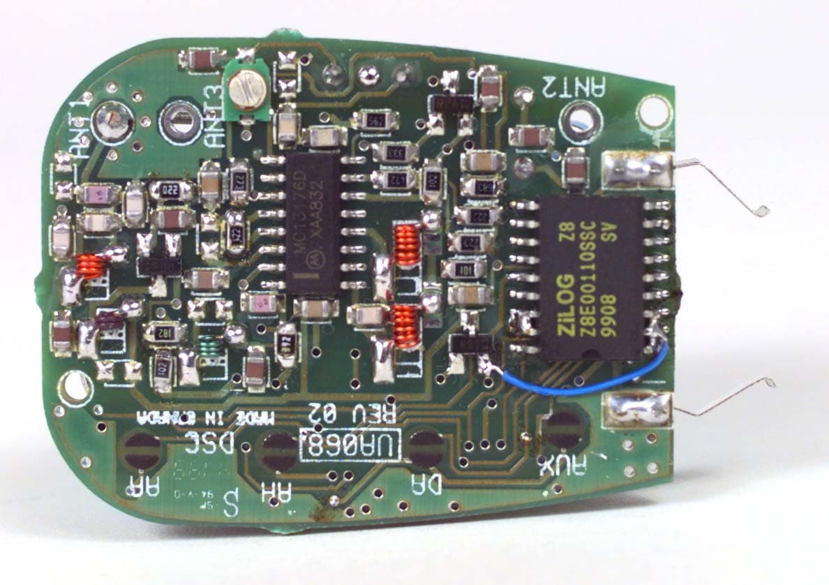
Click to zoom
Application Details
- Equipment Class
- DSC - Part 15 Security/Remote Control Transmitter
- Date of Grant
- May 01, 2000
- Application Purpose
- Original Equipment
- Date of Application
- Apr 19, 2000
- Equipment Note
- Pendant Transmitter
- Frequency Range
- 433.92000000 - 433.92000000
- Country
- Canada
Documents & Files
Document Text
Text extracted from the exhibit documents filed with the FCC. Open a document above to read the original.
Users Manual
WLS909NB Wireless Key OPERATING INSTRUCTIONS © 1999 Digital Security Controls Ltd. Printed in Canada 29004684 R001 Replacing WLS909NB Key Batteries To replace the batteries, remove the screw on the back of the key and carefully separate the two sides of the key’s plastic casing. Remove the old batteries from between the two metal clips. Insert the new batteries according to the diagram at right and reattach the two sides of the key’s plastic casing. The WLS909NB requires three batteries of type LR44. NOTE: The polarity of the batteries must be observed. WLS909NB TM key ring four option buttons – + LIMITED WARRANTY Digital Security Controls Ltd. warrants that for a period of twelve months from the date of purchase, the product shall be free of defect in materials and workmanship under normal use and that in fulfilment of any breach of such warranty, Digital Security Controls Ltd. shall, at its option, repair or replace the defective equipment upon return of the equipment to its repair depot. This warranty applies only to defects in parts and workmanship and not to damage incurred in shipping or handling, or damage due to causes beyond the control of Digital Security Controls Ltd. such as lightning, excessive voltage, mechanical shock, water damage, or damage arising out of abuse, alteration or improper application of the equipment. The foregoing warranty shall apply only to the original buyer, and is and shall be in lieu of any and all other warranties, whether expressed or implied and of all other obligations or liabilities on the part of Digital Security Controls Ltd. This warranty contains the entire warranty. Digital Security Controls Ltd. neither assumes, nor authorizes any other person purporting to act on its behalf to modify or to change this warranty, nor to assume for it any other warranty or liability concerning this product. In no event shall Digital Security Controls Ltd. be liable for any direct, indirect or consequential damages, loss of anticipated profits, loss of time or any other losses incurred by the buyer in connection with the purchase, installation or operation or failure of this product. WARNING: Digital Security Controls Ltd. recommends that the entire system be completely tested on a regular basis. However, despite frequent testing, and due to, but not limited to, criminal tampering or electrical disruption, it is possible for this product to fail to perform as expected. The WLS909NB wireless key allows you to arm and disarm your alarm system, as well as perform other keypad functions, from a unit small enough to keep in your pocket. Together with your installer, you can decide which functions you wish to have accessible from your portable key. To activate any one of the four selected functions, press and hold the appropriate button for two seconds. Your installer will indicate each function by applying a circular label beside each of the four buttons. Signals will not be received if the key is not within the range of the wireless receiver. Some of the most commonly used functions are as follows: Stay Arming Press this button to arm your system in the Stay mode. All perimeter zones will be armed, such as all window and door contacts, but the interior zones will remain inactive, allowing you to stay on the premises without setting off an alarm. Away Arming* Press this button to arm your system in the Away mode. Both the interior and exterior zones will be armed, allowing you to exit the premises. Disarm* Press this button to disarm your system. You do not have to enter your access code when you use the key to disarm the system. Fire Press this button to notify your central monitoring station of a fire condition. Auxiliary Press this button to notify your central monitoring station of a non-medical emergency. Please discuss the functionality of this button with your installer. Panic Press this button to notify your central monitoring station of a situation requiring the police, such as a break-in. Other options are available. Please discuss all WLS909NB options with your installer in order to program the best possible combination to suit your needs. *NOTE: In the UK some restrictions may apply. Please contact your installer for details. WLS909NB Wireless Key OPERATING INSTRUCTIONS © 1999 Digital Security Controls Ltd. Printed in Canada 29004684 R001 The WLS909NB wireless key allows you to arm and disarm your alarm system, as well as perform other keypad functions, from a unit small enough to keep in your pocket. Together with your installer, you can decide which functions you wish to have accessible from your portable key. To activate any one of the four selected functions, press and hold the appropriate button for two seconds. Your installer will indicate each function by applying a circular label beside each of the four buttons. Signals will not be received if the key is not within the range of the wireless receiver. Some of the most commonly used functions are as follows: Stay Arming Press this button to arm your system in the Stay mode. All perimeter zones will be armed, such as all window and door contacts, but the interior zones will remain inactive, allowing you to stay on the premises without setting off an alarm. Away Arming* Press this button to arm your system in the Away mode. Both the interior and exterior zones will be armed, allowing you to exit the premises. Disarm* Press this button to disarm your system. You do not have to enter your access code when you use the key to disarm the system. Fire Press this button to notify your central monitoring station of a fire condition. Auxiliary Press this button to notify your central monitoring station of a non-medical emergency. Please discuss the functionality of this button with your installer. Panic Press this button to notify your central monitoring station of a situation requiring the police, such as a break-in. Other options are available. Please discuss all WLS909NB options with your installer in ord…
Text truncated - open the document above for the full version.
Attestation Statements
April 14, 2000 Office of Engineering & Technology Federal Communications Commission Washington, D.C. 20554 Subject:Request for continuous confidentiality of technical information per sections 0.459 and 0.457 (d) (2) ( I) of CFR 47. FCC ID:F5300NB909 Dear Sir or Madam: Digital Security Controls Canada Ltd. is hereby filing this request for continuous confidentiality of the specified items submitted with the application for certification ( Form731 ) with proposed identifier F5300NB909. The technical documentation for which continuous confidentiality is sought is: (1) Schematic diagrams: This technical documentation is a part of the material supporting the Form 731 application for certification, which this request for confidentiality accompanies. The schematic diagrams disclose proprietary information and technical data which Digital Security Controls Ltd. would guard from its competitors and would not make available to the public. This proprietary information constitutes a trade secret and is not a part of the product documentation that would be made available to the customers of Digital Security Controls Ltd. It would be potentially injurious to Digital Security Controls Ltd. and to its investment in the development of this innovative proprietary product to make available for public disclosure the trade secret technical information specified in this request. If there are any questions about this request for continuous confidentiality regarding trade secrets and proprietary information embodied in the technical documentation filed in support of this Form 731 application, then please contact me via our toll-free telephone number. Yours truly, Kevin Harris Approval Services Manager 905-760-3000 Ext. 2378 Email: [email protected]
Cover Letter(s)
Offices In Hull (UK), Ottawa (Canada), Dallas (USA) And Arnhem (The Netherlands) April 20, 2000 Federal Communications Commission Equipment Authorization Branch 7435 Oakland Mills Road Columbia, Maryland 21046 USA KTL 3325 River Road RR #5 Ottawa, Ontario Canada K1V 1H2 Tel: 613-737-9680 Fax: 613-737-9691 Toll Free: 1-800-563-6336 Email: [email protected] Internet: www.ktl.com Dear Sir/Madam:Our File Ref. 9R02130 FCC ID: F5300NB909 Applicant: Digital Security Controls Ltd. Equipment: WLS909NB433 Pendant Transmitter FCC Confirmation no.: EA97410 We have successfully electronically filed all the required documentation for an application for certification in accordance with FCC Part 15 on the above mentioned equipment, April 20, 2000. Enclosed, please find a copy of FCC Remittance Form 159 (fees paid by VISA electronically), a copy of the FCC Form 731 confirmation number and a copy of the list of exhibits. If you require additional information, please do not hesitate to contact me at 1-800-563-6336 (extension 232). Thank you in advance for your assistance in this matter. Sincerely, Ruby Dulmage Regulatory Submissions Clerk KTL Ottawa Inc. [email protected] Encl.
ID Label/Location Info
REAR HOUSING OF THE UNIT SHOWING PLACEMENT OF LABEL (ACTUAL SIZE) 22 mm 12 mm FCC ID: F5300NB909MODEL: WLS909NB433CANADA XXX-XXX-XXXXIC: RSS/CNR210Digital Security ControlsMade in Canada XXXXXXXX Digital Security Controls Ltd.ISO9001 Registered3301 Langstaff Road, ConcordOntario, Canada L4K 4L2Phone: 905-760-3000Toll Free: 1-888-888-7838Fax: 905-760-3030 TM FCC/IC Labeling for Transmitter WLS909NB433 Wireless Key File: [wls909nb433 fcc+ic lb 1800XXXX.cdr] March 13, 2000 LABEL INFORMATIONTO BE ETCHEDINTO PLASTIC MOLDLABEL SHOWN ACTUAL SIZE FCC ID: F5300NB909 MODEL: WLS909NB433 CANADA XXX-XXX-XXXX IC: RSS/CNR210 Digital Security Controls Made in Canada XXXXXXXX
Operational Description
CIRCUIT DESCRIPTION Device: Narrow Band Transmitter Model: WLS909NB North America ESI Identifier: Schematic Diagram: Description: The narrow band KEY FOB transmitter ( NBTX ) sends the status information encoded appropriately to the control unit of the wireless security system after a button switch being activated. This unit consists of two main circuit sections. A control section with a microprocessor & digital logic and the RF transmitter. The control section receives status from button switch after activation and then coded to produce the ASK modulation signal. This section also controls transmitter activity. The transmitter consists of a crystal reference oscillator, a divide-by-32 prescaler, and a phase detector forming a phase-lock-loop ( PLL )system. The phase comparator compares the reference frequency and the divide-by-32 output signal frequency, if there is any difference, it will produce an error voltage to lock the free running CCO to 433.92MHz. A RF amplifier with matching compensation provides the output signal to the antenna.
Test Report
Master: ktlPT15231 Date: October 8, 1999 KTL Test Report:9R02130 Applicant:Digital Security Controls Ltd. 3301 Langstaff Road Concord, Ontario L4K 4L2 Equipment Under Test:WLS909NB433 Pendant Transmitter (E.U.T.) FCC ID:F5300NB909 In Accordance With:FCC Part 15, Subpart C For Low Power Transmitters Operating Periodically In The Band 40.66 - 40.77 MHz And Above 70 MHz Tested By:KTL Ottawa Inc. 3325 River Road, R.R. 5 Ottawa, Ontario K1V 1H2 Authorized By: K. Carr, Technologist Date: Total Number of Pages:24 KTL Ottawa FCC PART 15, SUBPART C FOR LOW POWER TRANSMITTERS PROJECT NO.: 9R02130 EQUIPMENT: WLS909NB433 Pendant Transmitter FCC ID: F5300NB909 Page 2 of 22 Table of Contents Section 1. Summary of Test Results.............................................................................................3 Section 2. Equipment Under Test (E.U.T.).................................................................................. 5 Section 3. Transmission Requirements ...................................................................................... 12 Section 4. Radiated Emissions ...................................................................................................15 Section 5. Occupied Bandwidth................................................................................................. 18 Section 6. Block Diagrams......................................................................................................... 20 Section 7. Test Equipment List..................................................................................................22 Annex A Restricted Bands.............................................................................................................A1 KTL Ottawa FCC PART 15, SUBPART C FOR LOW POWER TRANSMITTERS PROJECT NO.: 9R02130 EQUIPMENT: WLS909NB433 Pendant Transmitter FCC ID: F5300NB909 Page 3 of 22 Section 1.Summary of Test Results Manufacturer:Digital Security Controls Ltd. Model No.:WLS909NB433 Serial No.:None Date Received In Laboratory: February 24, 2000 KTL Identification No.: Item #1 General: All measurements are traceable to national standards. These tests were conducted on a sample of the equipment for the purpose of demonstrating compliance with Part 15, Subpart C, Paragraph 15.231. All tests were conducted using measurement procedure ANSI C63.4-1992. Radiated emissions are made on an open area test site. A description of the test facility is on file with the FCC. New SubmissionProduction Unit Class II Permissive ChangePre-Production Unit DS C Equipment Code THIS TEST REPORT RELATES ONLY TO THE ITEM(S) TESTED. THE FOLLOWING DEVIATIONS FROM, ADDITIONS TO, OR EXCLUSIONS FROM THE TEST SPECIFICATIONS HAVE BEEN MADE. See “ Summary of Test Data”. NVLAP LAB CODE: 100351-0 TESTED BY: _____________________________________ DATE: ___________________ Russell Grant, Wireless Group Manager TESTED BY: _____________________________________ DATE: ___________________ Glen Westwell, Technologist KTL Ottawa Inc. authorizes the above named company to reproduce this report provided it is reproduced in its entirety and for use by the company’s employees only. Any use which a third party makes of this report, or any reliance on or decisions to be made based on it, are the responsibility of s uc h thir d par ties . KT L Ottaw a Inc. accepts no responsibility f or damages , if any, s uf f er ed by any thir d par ty as a r es ult of dec is ions made or ac tions bas ed on this r epor t. T his r eport applies only to the items tested. KTL Ottawa FCC PART 15, SUBPART C FOR LOW POWER TRANSMITTERS PROJECT NO.: 9R02130 EQUIPMENT: WLS909NB433 Pendant Transmitter FCC ID: F5300NB909 Page 4 of 22 Summary Of Test Data Name of TestParagraph NumberResults Transmission Requirements15.231(a)Complies Radiated Emissions15.231(b)Complies Occupied Bandwidth15.231(c)Complies Frequency Tolerance15.231(d)Not Applicable Periodic Alternate Field Strength Requirements15.231(e)Not Applicable Powerline Conducted Emissions15.207Not Applicable Footnotes For N/A’s: Test Conditions: Indoor Temperature: 20 °C Humidity:20 % Outdoor Temperature: 10 °C Humidity:20 % KTL Ottawa FCC PART 15, SUBPART C FOR LOW POWER TRANSMITTERS PROJECT NO.: 9R02130 EQUIPMENT: WLS909NB433 Pendant Transmitter FCC ID: F5300NB909 Page 5 of 22 Section 2.Equipment Under Test (E.U.T.) General Equipment Information Frequency Range: 433.92 MHz Operating Frequency(ies) of Sample: 433.92 MHz Type of Emission: Pulse Width Modulation Emission Designator: 107KL1D Supply Power Requirement: Batteries Duty Cycle Calculation: -16.6 dB KTL Ottawa FCC PART 15, SUBPART C FOR LOW POWER TRANSMITTERS PROJECT NO.: 9R02130 EQUIPMENT: WLS909NB433 Pendant Transmitter FCC ID: F5300NB909 Page 6 of 22 KTL Ottawa FCC PART 15, SUBPART C FOR LOW POWER TRANSMITTERS PROJECT NO.: 9R02130 EQUIPMENT: WLS909NB433 Pendant Transmitter FCC ID: F5300NB909 Page 7 of 22 Data Transmission Format The transmitted data packet is a fixed length, amplitude modulated packet. The packet contains all of the necessary information to indicate which sensor generated the packet, the type of sensor and the status of the sensor’s inputs. The data is sent at a rate of 500 μS per bit or 2 Kbits per second. Figure 1 shows the bit timing used for all bits in the packet. Where a low logic present for the 500 μS bit time represents a data logic “0” and 250 μS low then 250 μS high represents a data logic “1”. Figure 1: Bit Timing Figure 2 shows the format of the transmitted data packet. Bytes highlighted are bytes that are variable information that would depend on the current status, module type and serial number of the particular device. Figure 2: Data Packet Format Because these bytes are variable there is a best and worst case packet when considering ON time. 250 μ S250 μ S 500 μ S bit time : data logic "0" 500 μ S bit time : data logic "1" 250 μ S250 μ S Sync bits (4 bits) Status Byte (8 bits) CRC Byte (8 bits) Serial Number Digits 4 and 5 (8 bits) Serial Number D…
Text truncated - open the document above for the full version.
Contact Information
Applicant
Dan Nita(Approvals Manager)
Technical Contact
Non-Technical Contact
KTL Ottawa Inc.Ruby C Dulmage
[email protected]800-563-6336
Test Firm
Nemko Canada Inc.Stuart Beck
Technical Specifications
| # | Rule Parts | Frequency Range | Power Output |
|---|---|---|---|
| 1 | 15C | 433.92 MHz - 433.92 MHz | - |
Other Applications from Tyco Safety Products Canada Ltd.

F53252RFLOCK
Jun 05, 2026IQ Lock-PGP, IQ Lock Touch-PGP
Equipment Class
DTS - Digital Transmission System
F5325PGPDC9
Apr 27, 2026PowerG wireless transceiver module
Equipment Class
DSS - Part 15 Spread Spectrum Transmitter
F5325LC203424
Dec 17, 2025Dual Technology Motion Sensor
Equipment Class
FDS - Part 15 Field Disturbance SensorF5324PGPIO9
Dec 04, 2024Wireless Input / Output (I/O) w/wo contact
Equipment Class
DSS - Part 15 Spread Spectrum Transmitter
F5323PGP9934P
Jan 16, 2024Wireless Motion detector with integrated camera
Equipment Class
DSS - Part 15 Spread Spectrum Transmitter