F5300NB925
Tyco Safety Products Canada Ltd.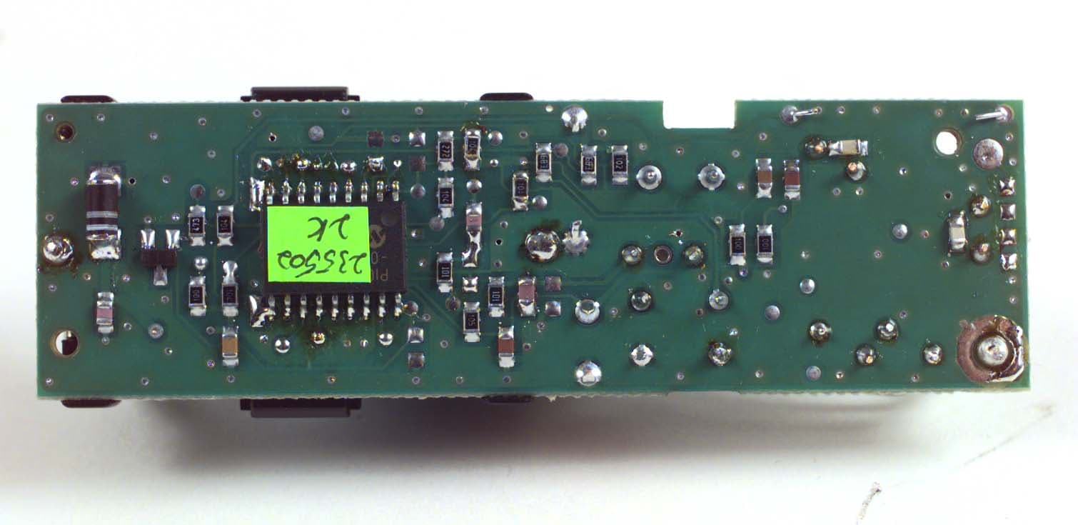
Click to zoom
Application Details
- Equipment Class
- DSC - Part 15 Security/Remote Control Transmitter
- Date of Grant
- Jun 18, 2000
- Application Purpose
- Original Equipment
- Date of Application
- May 18, 2000
- Frequency Range
- 433.92000000 - 433.92000000
- Country
- Canada
Documents & Files
Document Text
Text extracted from the exhibit documents filed with the FCC. Open a document above to read the original.
Users Manual
WLS925-433 Mini Door/Window Contact INSTALLATION INSTRUCTIONSINSTALLATION INSTRUCTIONS INSTALLATION INSTRUCTIONSINSTALLATION INSTRUCTIONS INSTALLATION INSTRUCTIONS © 2000 Digital Security Controls Ltd. Toronto, Canada 1-800-387-3630 • www.dscgrp.com Printed in Canada 29005100 R001 Remove Cover At the notched location on the cover, insert the flat blade of a small screwdriver between between between between between the base and the cover and twist the screwdriver to pop the cover off. Install Battery Use care when installing the battery and observe the correct polarity (see diagram below). Use only Eveready Lithium Energizer No. EL123AP battery. NOTE: Battery replacement must only be done by a qualified technician. Locate Transmitter Locate where the transmitter is to be mounted. Perform the Module Placement Test Module Placement Test Module Placement Test Module Placement Test Module Placement Test to ensure that the selected location is in range of the wireless receiver (see receiver Installation Manual for instruction). Determine where the magnet will be placed. In order to activate the reed switch, the magnet must line up with the end of the transmitter. Remove Circuit Board Before mounting the unit, remove the circuit board. At the notched location on the base which is on the same side as the reed switch, insert the blade of a small screwdriver between the base wall and the bottom of the circuit board and pry the circuit board up. NOTE: Do not touch the coils on the circuit board as this may damage the unit. Mount Transmitter and Magnet Mount the backplate of the transmitter using the screws provided and replace the circuit board. The head of the screw must be below the circuit board so that the sensor is not shorted out. Use flat-headed screws only. Mount the magnet no more than ¼” from the transmitter. Use the spacers provided . Once the unit and magnet are mounted, open and close the window/door to ensure that none of the parts interfere with this movement. Only one magnet can be used per transmitter. Using External Contacts The external contact terminals can be used to connect external contacts or other switches/devices to the universal transmitter. Install the additional device as per the manufacturer’s instruction. Connect the device to the contact terminals of the WLS925-433. The input is normally closed and is not supervised. For UL installations, the wires connecting the external device to the input terminals must not exceed 36" (90.5 cm) in length. The contact and transmitter must also be in the same room. For non-UL installations, the wires connecting the external device to the input terminals can be any length provided that the resistance of the wire does not exceed 100 ΩΩ ΩΩ Ω. Only one contact can be used. If an external contact is used, do not install the magnet. Tamper Switch There is one tamper switch on the WLS925 board. Removing the cover will cause a zone tamper. Enrolling a WLS925 On the back of the door contact housing, there will be two serial numbers, a five digit and six digit. Please refer to your receiver installation manual for information on which serial number should be enrolled. FCC COMPLIANCE STATEMENT CAUTION: Changes or modifications not expressly approved by Digital Security Controls Ltd. could void your authority to use this equipment. This equipment generates and uses radio frequency energy and if not installed and used properly, in strict accordance with the manufacturer’s instructions, may cause interference to radio and television reception. It has been type tested and found to comply with the limits for Class B device in accordance with the specifications in Subpart “B” of Part 15 of FCC Rules, which are designed to provide reasonable protection against such interference in any residential installation. However, there is no guarantee that interference will not occur in a particular installation. If this equipment does cause interference to television or radio reception, which can be determined by turning the equipment off and on, the user is encouraged to try to correct the interference by one or more of the following measures: • Re-orient the receiving antenna • Relocate the alarm control with respect to the receiver • Move the alarm control away from the receiver • Connect the alarm control into a different outlet so that alarm control and receiver are on different circuits. If necessary, the user should consult the dealer or an experienced radio/television technician for additional suggestions. The user may find the following booklet prepared by the FCC helpful: “How to Identify and Resolve Radio/Television Interference Problems”. This booklet is available from the U.S. Government Printing Office, Washington, D.C. 20402, Stock # 004-000-00345-4. Limited Warranty Digital Security Controls Ltd. warrants that for a period of twelve months from the date of purchase, the product shall be free of defects in material and workmanship under normal use and that in fulfillment of any breach of such warranty, Digital Security Controls Ltd. shall, at its option, repair or replace the defective equipment upon return of the equipment to its repair depot. This warranty applies only to defects in parts and workmanship and not to damage incurred in shipping or handling, or damage due to causes beyond control of Digital Security Controls Ltd. such as lightning, excessive voltage, mechanical shock, water damage, or damage arising out of abuse, alteration or improper application of the equipment. The foregoing warranty shall apply only to the original buyer, and is and shall be in lieu of any and all other warranties, whether express or implied and of all other obligations or liabilities on the part of Digital Security Controls Ltd. This warranty contains the entire warranty. Digital Security Controls Ltd. neither assumes, nor authorizes any other person purporting to act on its behalf to modify or to change this warranty, nor to assume for it any other warrant…
Text truncated - open the document above for the full version.
Attestation Statements
May 17, 2000 Office of Engineering & Technology Federal Communications Commission Washington, D.C. 20554 Subject:Request for continuous confidentiality of technical information per sections 0.459 and 0.457 (d) (2) ( I) of CFR 47. FCC ID:F5300NB925 Dear Sir or Madam: Digital Security Controls Canada Ltd. is hereby filing this request for continuous confidentiality of the specified items submitted with the application for certification ( Form731 ) with proposed identifier F5300NB925. The technical documentation for which continuous confidentiality is sought is: (1) Schematic diagrams: (2) Circuit/Technical description This technical documentation is a part of the material supporting the Form 731 application for certification, which this request for confidentiality accompanies. The schematic diagrams disclose proprietary information and technical data which Digital Security Controls Ltd. would guard from its competitors and would not make available to the public. This proprietary information constitutes a trade secret and is not a part of the product documentation that would be made available to the customers of Digital Security Controls Ltd. It would be potentially injurious to Digital Security Controls Ltd. and to its investment in the development of this innovative proprietary product to make available for public disclosure the trade secret technical information specified in this request. If there are any questions about this request for continuous confidentiality regarding trade secrets and proprietary information embodied in the technical documentation filed in support of this Form 731 application, then please contact me via our toll-free telephone number. Yours truly, Kevin Harris Approval Services Manager 905-760-3000 Ext. 2378 Email: [email protected]
ID Label/Location Info
FCC/ICES-003 Labeling for WLS925-433 Wireless Mini Door/Window Contact File: [wls925-4323_fcc+ices-003_lb_1800xxxx.cdr] April 18, 2000 ! ! ! Dashed line indicates cut edge of label Label to be printed on self-adhesive material Label shown 250% of actual size 35 mm 12.7 mm Bottom of the unit showing placement of label (Actual size) This device complies with Part 15 of the FCC Rules. Operation is subject to the following two conditions: (1) This device may not cause harmful in- terference, and (2) this device must accept any interference received, in- cluding interference that may cause undesired operation. WLS925-433 Digital Security Controls Ltd.1800xxxx R001 FCC ID: F5300NB925 IC: RSS/CNR210 CANADA XXX XXX XXXX MADE IN CANADA This Class B digital apparatus meets all requirements of the ICES-003. Cet appareil numérique de la classe B respecte toutes les exigences du ICES-003. Digital Security Controls Ltd. ISO9001 Registered 3301 Langstaff Road, Concord Ontario, Canada L4K 4L2 Phone: 905-760-3000 Toll Free: 1-888-888-7838 Fax: 905-760-3030 TM
ID Label/Location Info
FCC/ICES-003 Labeling for PWLS925-433 Wireless Mini Door/Window Contact File: [pwls925-433_fcc+ices-003_lb_1800xxxx.cdr] May 9, 2000 Dashed line indicates cut edge of label Label to be printed on self-adhesive material Label shown 250% of actual size 35 mm 12.7 mm Bottom of the unit showing placement of label (Actual size) Digital Security Controls Ltd. ISO9001 Registered 3301 Langstaff Road, Concord Ontario, Canada L4K 4L2 Phone: 905-760-3000 Toll Free: 1-888-888-7838 Fax: 905-760-3030 ® This device complies with Part 15 of the FCC Rules. Operation is subject to the following two conditions: (1) This device may not cause harmful in- terference, and (2) this device must accept any interference received, in- cluding interference that may cause undesired operation. PWLS925-433 Digital Security Controls Ltd.1800xxxx R001 IC: RSS/CNR210 CANADA XXX XXX XXXX MADE IN CANADA FCC ID: F5300NB925 This Class B digital apparatus meets all requirements of the ICES-003. Cet appareil numérique de la classe B respecte toutes les exigences du ICES-003.
ID Label/Location Info
FCC/ICES-003 Labeling for WLS925L-433 Wireless Mini Door/Window Contact File: [wls925l-433_fcc+ices-003_lb_1800xxxx.cdr] May 15, 2000 Dashed line indicates cut edge of label Label to be printed on self-adhesive material Label shown 250% of actual size 35 mm 12.7 mm Bottom of the unit showing placement of label (Actual size) Digital Security Controls Ltd. ISO9001 Registered 3301 Langstaff Road, Concord Ontario, Canada L4K 4L2 Phone: 905-760-3000 Toll Free: 1-888-888-7838 Fax: 905-760-3030 ® WLS925L-433 Digital Security Controls Ltd.1800xxxx R001 FCC ID: F5300NB925 IC: RSS/CNR210 CANADA XXX XXX XXXX MADE IN CANADA This device complies with Part 15 of the FCC Rules. Operation is subject to the following two conditions: (1) This device may not cause harmful in- terference, and (2) this device must accept any interference received, in- cluding interference that may cause undesired operation. This Class B digital apparatus meets all requirements of the ICES-003. Cet appareil numérique de la classe B respecte toutes les exigences du ICES-003.
ID Label/Location Info
FCC/ICES-003 Labeling for PWLS925L-433 Wireless Mini Door/Window Contact File: [pwls925l-433_fcc+ices-003_lb_1800xxxx.cdr] May 15, 2000 Dashed line indicates cut edge of label Label to be printed on self-adhesive material Label shown 250% of actual size 35 mm 12.7 mm Bottom of the unit showing placement of label (Actual size) Digital Security Controls Ltd. ISO9001 Registered 3301 Langstaff Road, Concord Ontario, Canada L4K 4L2 Phone: 905-760-3000 Toll Free: 1-888-888-7838 Fax: 905-760-3030 ® PWLS925L-433 Digital Security Controls Ltd.1800xxxx R001 FCC ID: F5300NB925 IC: RSS/CNR210 CANADA XXX XXX XXXX MADE IN CANADA This device complies with Part 15 of the FCC Rules. Operation is subject to the following two conditions: (1) This device may not cause harmful in- terference, and (2) this device must accept any interference received, in- cluding interference that may cause undesired operation. This Class B digital apparatus meets all requirements of the ICES-003. Cet appareil numérique de la classe B respecte toutes les exigences du ICES-003.
Test Report
Master: ktlPT15231 Date: April 5, 2000 KTL Test Report:0R02417 Applicant:Digital Security Controls Ltd. 3301 Langstaff Road Vaughn, Ontario L4K 4L2 Equipment Under Test:WLS 925-433 (E.U.T.) FCC ID:F5300NB925 In Accordance With:FCC Part 15, Subpart C For Low Power Transmitters Operating Periodically In The Band 40.66 - 40.77 MHz And Above 70 MHz Tested By:KTL Ottawa Inc. 3325 River Road, R.R. 5 Ottawa, Ontario K1V 1H2 Authorized By: R. Grant, Wireless Group Manager Date: Total Number of Pages:24 KTL Ottawa FCC PART 15, SUBPART C FOR LOW POWER TRANSMITTERS PROJECT NO.: 0R02417 EQUIPMENT: WLS 925-433 FCC ID: F5300NB925 Page 2 of 22 Table of Contents Section 1. Summary of Test Results.......................................................................................... 3 Section 2. Equipment Under Test (E.U.T.) .............................................................................. 5 Section 3. Transmission Requirements .................................................................................. 12 Section 4. Radiated Emissions................................................................................................. 15 Section 5. Occupied Bandwidth.............................................................................................. 18 Section 6. Block Diagrams.......................................................................................................20 Section 7. Test Equipment List ................................................................................................ 22 Annex A Restricted Bands.................................................................................................... A1 KTL Ottawa FCC PART 15, SUBPART C FOR LOW POWER TRANSMITTERS PROJECT NO.: 0R02417 EQUIPMENT: WLS 925-433 FCC ID: F5300NB925 Page 3 of 22 Section 1.Summary of Test Results General All measurements are traceable to national standards. These tests were conducted on a sample of the equipment for the purpose of demonstrating compliance with Part 15, Subpart C, Paragraph 15.231. All tests were conducted using measurement procedure ANSI C63.4-1992. Radiated emissions are made on an open area test site. A description of the test facility is on file with the FCC. New SubmissionProduction Unit Class II Permissive ChangePre-Production Unit DS C Equipment Code THIS TEST REPORT RELATES ONLY TO THE ITEM(S) TESTED. THE FOLLOWING DEVIATIONS FROM, ADDITIONS TO, OR EXCLUSIONS FROM THE TEST SPECIFICATIONS HAVE BEEN MADE. See “ Summary of Test Data”. NVLAP LAB CODE: 100351-0 TESTED BY: _____________________________________ DATE: ___________________ Glen Westwell. Technologist KTL Ottawa Inc. authorizes the above named company to reproduce this report provided it is reproduced in its entirety and for use by the company’s employees only. Any use which a third party makes of this report, or any reliance on or decisions to be made based on it, are the responsibility of such third parties. KTL Ottawa Inc. accepts no responsibility for damages, if any, suffered by any third party as a result of decisions made or actions based on this report. This report applies only to the items tested. KTL Ottawa FCC PART 15, SUBPART C FOR LOW POWER TRANSMITTERS PROJECT NO.: 0R02417 EQUIPMENT: WLS 925-433 FCC ID: F5300NB925 Page 4 of 22 Summary Of Test Data Name of TestPara. NumberResults Transmission Requirements15.231(a)Complies Radiated Emissions15.231(b)Complies Occupied Bandwidth15.231(c)Complies Frequency Tolerance15.231(d)Not Applicable Periodic Alternate Field Strength Requirements15.231(e)Not Applicable Powerline Conducted Emissions15.207Not Applicable Footnotes For N/A’s: Test Conditions: Indoor Temperature: 22 °C Humidity:25 % Outdoor Temperature: 4 °C Humidity:22 % KTL Ottawa FCC PART 15, SUBPART C FOR LOW POWER TRANSMITTERS PROJECT NO.: 0R02417 EQUIPMENT: WLS 925-433 FCC ID: F5300NB925 Page 5 of 22 Section 2.Equipment Under Test (E.U.T.) General Equipment Information Manufacturer: Digital Security Controls Ltd. Model No.: WLS 925-433 Serial No.: 235502 Date Received In Laboratory: April 17, 2000 KTL Identification No.: Item #2 Frequency Range: 433.920 MHz (Fixed) Operating Frequency(ies) of Sample: 433.92MHz Type of Emission: Pulse Width Modulation Emission Designator: 183KL1D Supply Power Requirement: 3 Vdc Battery Duty Cycle Calculation: -18 dB (See Attached Duty Cycle Description & Time Domain Graphs) Duty Cycle = 20 Log mS mS 100 25.12 = 18.24 dB KTL Ottawa FCC PART 15, SUBPART C FOR LOW POWER TRANSMITTERS PROJECT NO.: 0R02417 EQUIPMENT: WLS 925-433 FCC ID: F5300NB925 Page 6 of 22 KTL Ottawa FCC PART 15, SUBPART C FOR LOW POWER TRANSMITTERS PROJECT NO.: 0R02417 EQUIPMENT: WLS 925-433 FCC ID: F5300NB925 Page 7 of 22 Data Transmission Format The transmitted data packet is a fixed length, amplitude modulated packet. The packet contains all of the necessary information to indicate which sensor generated the packet, the type of sensor and the status of the sensor’s inputs. The data is sent at a rate of 500 μS per bit or 2 Kbits per second. Figure 1 shows the bit timing used for all bits in the packet. Where a low logic present for the 500 μS bit time represents a data logic “0” and 250 μS low then 250 μS high represents a data logic “1”. Figure 1 – Bit Timing Figure 2 shows the format of the transmitted data packet. Bytes highlighted in green are bytes that are variable information that would depend on the current status, module type and serial number of the particular device. Figure 2 – Data Packet Format Because these bytes are variable there is a best and worst case packet when considering ON Time. 250 μ S250 μ S 500 μ S bit time : data logic "0" 500 μ S bit time : data logic "1" 250 μ S250 μ S Sync bits (4 bits) Status Byte (8 bits) CRC Byte (8 bits) Serial Number Digits 4 and 5 (8 bits) Serial Number Digits 2 and 3 (8 bits) Module Type (4 bits) Serial Number Digit 1 (4 bits) Start bit (1 bit) Start bit (1 bit) Start bit (1 bit) Start bit (1 bit) Header (2.5 ms Constant M…
Text truncated - open the document above for the full version.
Contact Information
Applicant
Dan Nita(Approvals Manager)
Technical Contact
Non-Technical Contact
KTL Ottawa Inc.Ruby C Dulmage
[email protected]800-563-6336
Test Firm
Nemko Canada Inc.Stuart Beck
Technical Specifications
| # | Rule Parts | Frequency Range | Power Output |
|---|---|---|---|
| 1 | 15C | 433.92 MHz - 433.92 MHz | - |
Other Applications from Tyco Safety Products Canada Ltd.

F53252RFLOCK
Jun 05, 2026IQ Lock-PGP, IQ Lock Touch-PGP
Equipment Class
DTS - Digital Transmission System
F5325PGPDC9
Apr 27, 2026PowerG wireless transceiver module
Equipment Class
DSS - Part 15 Spread Spectrum Transmitter
F5325LC203424
Dec 17, 2025Dual Technology Motion Sensor
Equipment Class
FDS - Part 15 Field Disturbance SensorF5324PGPIO9
Dec 04, 2024Wireless Input / Output (I/O) w/wo contact
Equipment Class
DSS - Part 15 Spread Spectrum Transmitter
F5323PGP9934P
Jan 16, 2024Wireless Motion detector with integrated camera
Equipment Class
DSS - Part 15 Spread Spectrum Transmitter