F5301LC906WLS906-433, WLS906-433EU & WLS906-433NA SMOKE DETE
Tyco Safety Products Canada Ltd.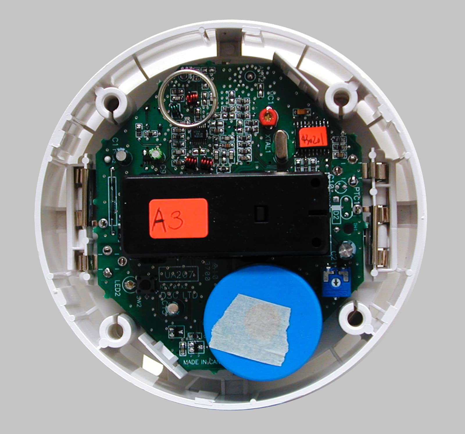
Click to zoom
Application Details
- Equipment Class
- DSC - Part 15 Security/Remote Control Transmitter
- Date of Grant
- Mar 12, 2001
- Application Purpose
- Original Equipment
- Date of Application
- Jan 21, 2001
- Equipment Note
- WLS906-433, WLS906-433EU & WLS906-433NA SMOKE DETE
- Frequency Range
- 433.92000000 - 433.92000000
- Country
- Canada
Documents & Files
Document Text
Text extracted from the exhibit documents filed with the FCC. Open a document above to read the original.
Users Manual
How the Smoke Detector Works As shown in the illustration, a light source is directed across the smoke chamber and is not normally reflected into the sensing element. When smoke enters the chamber, the light beam is scattered by the smoke and is reflected into the sensor. When enough light is detected by the sensor, an alarm is activated. On alarm, the sounder is activated and the red LED will flash. When the smoke clears from the smoke chamber, the unit will automatically reset itself. Alarm Indications ConditionSounderIndicatorRF LightTransmission No smokeSilentFlash everySupervision transmission 40-50 severy 12 min. for Europe / every 64 min. for North America SmokeAlarmFlash everyAlarm 0.67 stransmission Automatic self testSilentFlash everySupervision transmission functioning normally40-50 severy 12 min. for Europe / every 64 min. for North America Automatic self testChirp betweenFlash everyFire Trouble insufficient sensitivity LED flashes40-50 stransmission Push-button testAlarmFlash everySupervision transmission functioning normally0.67 severy 12 min. for Europe / every 64 min. for North America Push-button testSilentFlash everyFire Trouble insufficient sensitivity40-50 s transmission Magnet/reed switchAlarmFlash everyAlarm test functioning normally0.67 stransmission Magnet/reed switchSilentFlash everyFire Trouble test insufficient40-50 stransmission sensitivity Low batteryChirp simultaneousFlash everyFire Trouble with LED flash40-50 stransmission Limitations of Smoke Detectors While the Meridian smoke detector has been designed for reliability, it is important to know that all smoke detectors have limitations. • Smoke detectors will not work without power. If the batteries are low, the smoke detector will not function. See ‘Battery Installation’ below for important information on battery use. • Smoke detectors can only generate an alarm when smoke gets inside the smoke chamber; anything that prevents smoke from entering the smoke chamber may prevent or delay an alarm. Refer to the ‘Guidelines for Locating Smoke Detectors’ on this Instruction Sheet; it is important that smoke detectors be located on at least every floor of the premises, preferably in every room. It is also important to avoid obstructions, such as closed doors, that may prevent smoke from reaching the unit. A smoke detector will not detect a fire in the walls, in the chimney or on the roof of a building until smoke enters the smoke chamber. READ THIS INSTRUCTION SHEET THOROUGHLY BEFORE INSTALLING AND USING YOUR MERIDIAN SMOKE DETECTOR Features • Advanced 90° photoelectric detection pattern and specially designed smoke chamber ∗∗ ∗∗ ∗ for superior detection and dust resistance • Unique high signal-to-noise ratio and superior RFI immunity to prevent false alarms • Excellent smoke access provides reliable detection for all smoke flow directions and velocities • Loud 85dB piezoelectric alarm horn • Battery-powered design for easy installation and independence from house power sources • Uses six AA batteries and special circuit design to provide extra long battery life • Solid-state LED indicator light (red) • Visible flash light and audible trouble chirp for low battery warning • Equipped with an RF transmitter, WLS906 can communicate with compatible DSC Wireless Security Systems • Test Button allows user to perform sensitivity test and get a local indication of test result • Magnet-activated reed switch allows user to perform system test • Battery removal sensor alerts user to missing battery and prevents installation of detector when no battery is installed • Automatic self-test once every 40 seconds provides an audible trouble indication if the unit has insufficient smoke sensitivity • Attractive styling for any decor ∗∗ ∗∗ ∗ Protected under Canadian Patent No. 1452296. Other patents pending. Introduction The DSC Meridian photoelectric smoke detector incorporates many advanced design features to provide years of reliable operation. It is important to follow the installation and operation instructions on this sheet to ensure that the unit will function properly — even the best designed smoke detector will be rendered useless if it is not connected or located properly. It is very important that you understand how to test and maintain your system. Read the Instruction or User Manual for your alarm system to familiarize yourself with the fire alarm functions. Be sure to test your system regularly following the test procedures described in your manual. If you should ever have problems operating or testing your system, and especially if there are problems with the fire alarm functions, contact your smoke detector installer or dealer immediately for service. While smoke detectors and alarm systems are designed to warn you of potentially dangerous situations, no system can prevent emergencies. An alarm system is not a substitute for life and property insurance; you should always maintain appropriate insurance coverage. WLS906-433 Battery-Powered Smoke Detectors For Residential Use INSTRUCTIONS FOR INSTALLATION AND USE • Smoke detectors have certain obvious limitations: they may not provide protection for someone smoking in bed, for children playing with matches, or for sudden and violent explosions. A smoke detector is a single part of overall fire safety precautions; the smoke detector should never be seen as a substitute for a complete fire safety program. Guidelines for Locating Smoke Detectors On smooth ceilings, detectors may be spaced 9.1m (30 feet) apart as a guide. Other spacing may be required depending on ceiling height, air movement, the presence of joists, uninsulated ceilings, etc. Consult National Fire Alarm Code NFPA 72, CAN/ULS-S553- M86 or other appropriate national standards for installation recommendations. Do not locate smoke detectors at the top of peaked or gabled ceilings; the dead air space in these locations may prevent the unit from detecting smoke. Avoid areas with turbulent air flow, such as near …
Text truncated - open the document above for the full version.
Attestation Statements
December 7, 2000 Office of Engineering & Technology Federal Communications Commission Washington, D.C. 20554 Subject:Request for continuous confidentiality of technical information per sections 0.459 and 0.457 (d) (2) ( I) of CFR 47. FCC ID:F5301LC906 Dear Sir or Madam: Digital Security Controls Canada Ltd. is hereby filing this request for continuous confidentiality of the specified items submitted with the application for certification ( Form731 ) with proposed identifier F5301LC906. The technical documentation for which continuous confidentiality is sought is: (1) Schematic diagrams: (2) Block Diagram This technical documentation is a part of the material supporting the Form 731 application for certification, which this request for confidentiality accompanies. The schematic diagrams disclose proprietary information and technical data which Digital Security Controls Ltd. would guard from its competitors and would not make available to the public. This proprietary information constitutes a trade secret and is not a part of the product documentation that would be made available to the customers of Digital Security Controls Ltd. It would be potentially injurious to Digital Security Controls Ltd. and to its investment in the development of this innovative proprietary product to make available for public disclosure the trade secret technical information specified in this request. If there are any questions about this request for continuous confidentiality regarding trade secrets and proprietary information embodied in the technical documentation filed in support of this Form 731 application, then please contact me via our toll-free telephone number. Yours truly, Kevin Harris Approval Services Manager 905-760-3000 Ext. 2378 Email: [email protected]
Cover Letter(s)
January 6, 2001 Ref.: FCC Part 15 & RSS 210 Registration of the models WLS906-433, WLS906-433EU and WLS906-433NA To Whom It May Concern: The radio applications between models WLS906-433, WLS906-433EU and WLS906-433NA are identical. The only difference between these three models being marketing literature. Yours truly, Kevin Harris Approvals Services Manager Email: [email protected] Tel: 1-888-888-7838 Ext. 2378
ID Label/Location Info
Digital Security Controls Ltd.ISO9001 Registered3301 Langstaff Road, ConcordOntario, Canada L4K 4L2Phone: 905-760-3000Toll Free: 1-888-888-7838Fax: 905-760-3030 ® FCC/IC Labeling for WLS906-433 Wireless Smoke Detector Side of the unit showing placement of label (actual size) File: [wls906-433_fcc+ic_lb_18007684_r001.cdr] Dec 8, 2000 DASHED LINE INDICATESCUT EDGE OF LABELLABEL TO BE PRINTEDON SELF-ADHESIVEMATERIALLABEL SHOWN 250% ACTUAL SIZE 44.5 mm 9.5 mm FCC ID: F5301LC906 Model: WLS906-433 Digital Security Controls Ltd. This device complies with Part 15 of the FCC Rules. Operation is subject to the following two con-ditions: (1) This device may not cause harmful interference, and (2) this device must accept anyinterference received, including interference that may cause undesired operation.IC: RSS/CNR210 CANADA: XXX XXX XXXX MADE IN CANADA 18007684 R001 This Class B digital apparatus meets all requirements of the ICES-003. Cet appareil numériquede la classe B respecte toutes les exigences du ICES-003.
ID Label/Location Info
Digital Security Controls Ltd.ISO9001 Registered3301 Langstaff Road, ConcordOntario, Canada L4K 4L2Phone: 905-760-3000Toll Free: 1-888-888-7838Fax: 905-760-3030 ® FCC/IC Labeling for WLS906-433EU Wireless Smoke Detector Side of the unit showing placement of label (actual size) File: [wls906-433EU_fcc+ic_lb_1800xxxx_r001.cdr] Dec 8, 2000 DASHED LINE INDICATESCUT EDGE OF LABELLABEL TO BE PRINTEDON SELF-ADHESIVEMATERIALLABEL SHOWN 250% ACTUAL SIZE 44.5 mm 9.5 mm FCC ID: F5301LC906 Model: WLS906-433EU Digital Security Controls Ltd. This device complies with Part 15 of the FCC Rules. Operation is subject to the following two con-ditions: (1) This device may not cause harmful interference, and (2) this device must accept anyinterference received, including interference that may cause undesired operation.IC: RSS/CNR210 CANADA: XXX XXX XXXX MADE IN CANADA 1800xxxx R001 This Class B digital apparatus meets all requirements of the ICES-003. Cet appareil numériquede la classe B respecte toutes les exigences du ICES-003.
ID Label/Location Info
Digital Security Controls Ltd.ISO9001 Registered3301 Langstaff Road, ConcordOntario, Canada L4K 4L2Phone: 905-760-3000Toll Free: 1-888-888-7838Fax: 905-760-3030 ® FCC/IC Labeling for WLS906-433NA Wireless Smoke Detector Side of the unit showing placement of label (actual size) File: [wls906-433NA_fcc+ic_lb_1800xxxx_r001.cdr] Dec 8, 2000 DASHED LINE INDICATESCUT EDGE OF LABELLABEL TO BE PRINTEDON SELF-ADHESIVEMATERIALLABEL SHOWN 250% ACTUAL SIZE 44.5 mm 9.5 mm FCC ID: F5301LC906 Model: WLS906-433NA Digital Security Controls Ltd. This device complies with Part 15 of the FCC Rules. Operation is subject to the following two con-ditions: (1) This device may not cause harmful interference, and (2) this device must accept anyinterference received, including interference that may cause undesired operation.IC: RSS/CNR210 CANADA: XXX XXX XXXX MADE IN CANADA 1800xxxx R001 This Class B digital apparatus meets all requirements of the ICES-003. Cet appareil numériquede la classe B respecte toutes les exigences du ICES-003.
Operational Description
CIRCUIT DESCRIPTION Device: Low Cost Narrow Band Smoke Detector Model: WLS906LC (UA207) ESI Identifier: Description: The low cost narrowband Smoke Detector (LCNB SMK) sends the sensor status appropriately to the control unit of the wireless security system. A Smoke chamber is incorporated to sense any obscurity above its set threshold sensitivity level, If found to be higher, the sensor will immediately trigger the Transmitter to send status to the controlling unit. This unit consists of Three main circuit sections. A control section with a microprocessor, a digital controls sensor section and the RF transmitter. The control section receives status information from the sensor inputs triggered by detecting obscurity in the smoke chamber apart from its normal operating function. It is then coded to produce ASK modulation signal. This section also controls transmitter activity. The transmitter consist of an integrated chip fully implemented with a phase locked loop (PLL), divide-by-64 prescaler, a phase detector, a voltage controlled oscillator, and an automatic lock detect that disables the transmitter output when the PLL is out of lock. The external reference crystal frequency provide a complete phase-locked detector which when divide-by-64 produce the output signal frequency of 433.92MHz compensated with a matching network to antenna.
Test Report
Master: ktlPT15231 Date: April 5, 2000 KTL Test Report:0R03329.2 Applicant:Digital Security Controls Ltd. 3301 Langstaff Road Vaughan, Ontario L4K 4L2 Equipment Under Test:WLS906-433 (E.U.T.)Smoke Detector In Accordance With:FCC Part 15, Subpart C For Low Power Transmitters Operating Periodically In The Band 40.66 - 40.77 MHz And Above 70 MHz Tested By:KTL Ottawa Inc. 3325 River Road, R.R. 5 Ottawa, Ontario K1V 1H2 Authorized By: G. Westwell, Technologist Date: Total Number of Pages:23 KTL Ottawa FCC PART 15, SUBPART C FOR LOW POWER TRANSMITTERS PROJECT NO.: 0R03329.2 EQUIPMENT: WLS906-433 Smoke Detector Page 2 of 23 Table of Contents Section 1. Summary of Test Results.......................................................................................... 3 Section 2. Equipment Under Test (E.U.T.) .............................................................................. 5 Section 3. Transmission Requirements .................................................................................. 13 Section 4. Radiated Emissions................................................................................................. 16 Section 5. Occupied Bandwidth.............................................................................................. 19 Section 9. Block Diagrams.......................................................................................................21 Section 6. Test Equipment List ............................................................................................... 23 KTL Ottawa FCC PART 15, SUBPART C FOR LOW POWER TRANSMITTERS PROJECT NO.: 0R03329.2 EQUIPMENT: WLS906-433 Smoke Detector Page 3 of 23 Section 1.Summary of Test Results General All measurements are traceable to national standards. These tests were conducted on a sample of the equipment for the purpose of demonstrating compliance with Part 15, Subpart C, Paragraph 15.231. All tests were conducted using measurement procedure ANSI C63.4-1992. Radiated emissions are made on an open area test site. A description of the test facility is on file with the FCC. New SubmissionProduction Unit Class II Permissive ChangePre-Production Unit DS C Equipment Code THIS TEST REPORT RELATES ONLY TO THE ITEM(S) TESTED. THE FOLLOWING DEVIATIONS FROM, ADDITIONS TO, OR EXCLUSIONS FROM THE TEST SPECIFICATIONS HAVE BEEN MADE. See “ Summary of Test Data”. NVLAP LAB CODE: 100351-0 TESTED BY: _____________________________________ DATE: ___________________ Russell Grant, Wireless Group Manager KTL Ottawa Inc. authorizes the above named company to reproduce this report provided it is reproduced in its entirety and for use by the company’s employees only. Any use which a third party makes of this report, or any reliance on or decisions to be made based on it, are the responsibility of such third parties. KTL Ottawa Inc. accepts no responsibility for damages, if any, suffered by any third party as a result of decisions made or actions based on this report. This report applies only to the items tested. KTL Ottawa FCC PART 15, SUBPART C FOR LOW POWER TRANSMITTERS PROJECT NO.: 0R03329.2 EQUIPMENT: WLS906-433 Smoke Detector Page 4 of 23 Summary Of Test Data Name of TestPara. NumberResults Transmission Requirements15.231(a)Complies Radiated Emissions15.231(b)Complies Occupied Bandwidth15.231(c)Complies Frequency Tolerance15.231(d)Not Applicable Periodic Alternate Field Strength Requirements15.231(e)Not Applicable Powerline Conducted Emissions15.207Not Applicable KTL Ottawa FCC PART 15, SUBPART C FOR LOW POWER TRANSMITTERS PROJECT NO.: 0R03329.2 EQUIPMENT: WLS906-433 Smoke Detector Page 5 of 23 Section 2.Equipment Under Test (E.U.T.) General Equipment Information Manufacturer: Digital Security Controls Ltd. Date Received In Laboratory: November 27, 2000 KTL Identification No.: Items #4 & 5 Frequency Range: 433.92 MHz Emission Designator: 105 KL1D Supply Power Requirement: Batteries Duty Cycle Calculation: 20 log 100 25.12 = -18.23 dB KTL Ottawa FCC PART 15, SUBPART C FOR LOW POWER TRANSMITTERS PROJECT NO.: 0R03329.2 EQUIPMENT: WLS906-433 Smoke Detector Page 6 of 23 KTL Ottawa FCC PART 15, SUBPART C FOR LOW POWER TRANSMITTERS PROJECT NO.: 0R03329.2 EQUIPMENT: WLS906-433 Smoke Detector Page 7 of 23 KTL Ottawa FCC PART 15, SUBPART C FOR LOW POWER TRANSMITTERS PROJECT NO.: 0R03329.2 EQUIPMENT: WLS906-433 Smoke Detector Page 8 of 23 KTL Ottawa FCC PART 15, SUBPART C FOR LOW POWER TRANSMITTERS PROJECT NO.: 0R03329.2 EQUIPMENT: WLS906-433 Smoke Detector Page 9 of 23 KTL Ottawa FCC PART 15, SUBPART C FOR LOW POWER TRANSMITTERS PROJECT NO.: 0R03329.2 EQUIPMENT: WLS906-433 Smoke Detector Page 10 of 23 KTL Ottawa FCC PART 15, SUBPART C FOR LOW POWER TRANSMITTERS PROJECT NO.: 0R03329.2 EQUIPMENT: WLS906-433 Smoke Detector Page 11 of 23 KTL Ottawa FCC PART 15, SUBPART C FOR LOW POWER TRANSMITTERS PROJECT NO.: 0R03329.2 EQUIPMENT: WLS906-433 Smoke Detector Page 12 of 23 KTL Ottawa FCC PART 15, SUBPART C FOR LOW POWER TRANSMITTERS PROJECT NO.: 0R03329.2 EQUIPMENT: WLS906-433 Smoke Detector Page 13 of 23 Section 3.Transmission Requirements Para. No.: 15.231(a) Test Performed By: Russell Grant Date of Test: November 28, 2000 Minimum Standard: 15.231(a) Continuous transmissions such as voice, video or data transmissions are not permitted. 15.231(a)(1) A manually operated transmitter shall employ a switch that will automatically deactivate the transmitter within not more than 5 seconds after being released. 15.231(a)(2) A transmitter activated automatically shall cease transmission within 5 seconds of activation. 15.231(a)(3) Periodic transmissions at regular pre-determined intervals are not permitted. However polling or supervisory transmissions to determine system integrity of transmitters used in security or safety applications are allowed if the periodic rate of transmission does not exceed one transmission of not more than one second duration per hour for each transmitter. 15.231(a)(4) Intentional radiators which are employed…
Text truncated - open the document above for the full version.
Contact Information
Applicant
Dan Nita(Approvals Manager)
Technical Contact
KTL OTTAWA INC.RUBY C DULMAGE
[email protected]613-737-9680
3325 RIVER ROAD · OTTAWA, ONTARIO · Canada
Non-Technical Contact
KTL OTTAWA INC.RUBY C DULMAGE
[email protected]613-737-9680
Test Firm
Nemko Canada Inc.Stuart Beck
Technical Specifications
| # | Rule Parts | Frequency Range | Power Output |
|---|---|---|---|
| 1 | 15C | 433.92 MHz - 433.92 MHz | - |
Other Applications from Tyco Safety Products Canada Ltd.

F53252RFLOCK
Jun 05, 2026IQ Lock-PGP, IQ Lock Touch-PGP
Equipment Class
DTS - Digital Transmission System
F5325PGPDC9
Apr 27, 2026PowerG wireless transceiver module
Equipment Class
DSS - Part 15 Spread Spectrum Transmitter
F5325LC203424
Dec 17, 2025Dual Technology Motion Sensor
Equipment Class
FDS - Part 15 Field Disturbance SensorF5324PGPIO9
Dec 04, 2024Wireless Input / Output (I/O) w/wo contact
Equipment Class
DSS - Part 15 Spread Spectrum Transmitter
F5323PGP9934P
Jan 16, 2024Wireless Motion detector with integrated camera
Equipment Class
DSS - Part 15 Spread Spectrum Transmitter