F5302WLS904PLNBPIR Motion Detector
Tyco Safety Products Canada Ltd.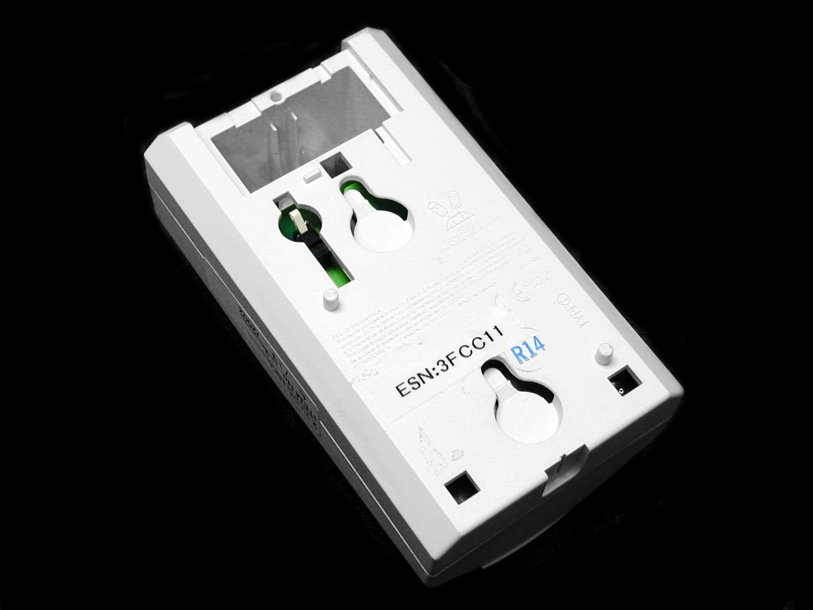
Click to zoom
Application Details
- Equipment Class
- DSC - Part 15 Security/Remote Control Transmitter
- Date of Grant
- Jul 14, 2002
- Application Purpose
- Original Equipment
- Date of Application
- Jul 14, 2002
- Equipment Note
- PIR Motion Detector
- Frequency Range
- 433.92000000 - 433.92000000
- Country
- Canada
Documents & Files
Document Text
Text extracted from the exhibit documents filed with the FCC. Open a document above to read the original.
Users Manual
WLS904PL-433 - Installation Instructions The WLS904PL detector is designed to combine the convenience of a wireless detector with effective and reliable detection of hu man motion as well as good protection against the nuisance alarms associated with pets weighing up to 60 lbs (27.3kg). Installing the DetectorThe WLS904PL detector provides effective immunity to single or multiple pets whose total combined weight does not exceed 60 lbs . (27.3kg) when installed and configured in the following manner. LocationSelect a detector location that will provide the coverage required and will allow the detector to be mounted a minimum of 6 ½ f t (1.95m) high and not higher than 10ft (3m) (7½ ft / 2.3m recommended). Consider the following to avoid false alarms:• Do not aim the detector at a stairwell to which a pet has access. • Do not place furniture or objects higher than 3ft (0.9m) which a pet can climb onto (e.g. a cat on a couch), closer than 6ft ( 1.8m) from the detector. • Mount the detector flat on a wall or in a corner. Do not angle it downwards or use mounting brackets with this detector when i t is used in conjunction with pets. • Do not aim the detector at reflective surfaces such as mirrors or windows as this may distort the coverage pattern or reflect sunlight directly onto the detector. • Avoid locations that are subject to direct high air flow such as near an air duct outlet. • Do not locate the detector near sources of moisture such as steam or oil. • Do not limit the coverage by large obstructions in the detection area such as plants or cabinets. • For indoor use only. NOTE: No detector should be mounted without first performing a module placement test to determine that it is in range of the wireles s receiver. See the Placement Test instructions in the Instruction Sheet for your receiver, or in the Installation Manual for you r system. When a location has been selected, remove the plastic from the mounting holes and locate the backplate on the wall and mark scr ew locations. It is suggested that wall anchors be used for all screw locations. Secure the backplate to the wall, and then secure the enrolled detector to its backplate.NOTE: Use only backplates marked as “Type-L”. Using any other backplates will result in the tamper switch being broken. CAUTION: The coils and antenna on the WLS904PL circuit board are very sensitive components precisely adjusted for maximum performance. Do not touch the coils or antenna! Even minor distortions can affect the performance of the motion detector. Enrolling a WLS904PLOn the back of the PIR housing, there will be two serial numbers: a five-digit number and a six-digit number. Please refer to y our receiver Installation Manual for information on which serial number should be enrolled. Changing the Sensitivity SettingThe WLS904PL features “Fast” and “Slow” settings on jumper J1, which is used to configure the detector for the weight of the pe t(s) and the environment. For an environment with a single pet whose weight does not exceed 30lbs (13.6kg) the jumper should be set to “Fast ” setting. In an environment with single or multiple pets whose combined weight is greater than 30lbs (13.6kg) but not greater than 60 lbs. (27.3kg), the jumper must be set to the “Slow” setting. When the detector is mounted 6 ½ ft to 7 ½ ft high (1.95 to 2.3 m) or there is the po ssibility of the pet getting higher than 4ft (1.2 m ) the "slow" setting must be used. To change the setting from Slow to Fast, move the jumper over one pin, as shown in the diagram. High Traffic Shutdown ModeTo prolong battery life, the motion detector uses a feature called High Traffic Shutdown. When motion is detected, the device w ill transmit to the receiver and will then shut down for three minutes. If motion is detected again during the shutdown time, the unit will not tra nsmit the event to the receiver. The detector will thus remain in the shutdown mode until three minutes after the first motion detected was transm itted. The detector will transmit detected motion every three minutes.The High Traffic Shutdown Mode affects testing the motion detector in two ways:When performing the module placement test , the unit must be tampered by removing the unit from the backplate and replacing it. The placement test cannot be performed by creating motion in front of the device. When performing a system test , the unit must be left idle for three minutes before testing can be performed. Once three minutes has passed, create motion in front of the detector to see if the device is both detecting motion and transmitting to the receiver.NOTE: Refer to the PC5132 or the System Installation Instructions for UL/ULC requirements. For UL/ULC installations where the WLS904PL is used on entry or exit delay zones, the entry delay must not be longer than 39 seconds, and the exit delay must not be longer than 54 seconds. Motion Detector Transmission DelayA motion detector transmission is always delayed by six seconds. This is necessary to prevent false alarms caused by a motion s ensor transmitting before a delay zone has a chance to report. This six-second delay cannot be altered or disabled.Walk Test ModeThe motion detector has a walk test mode which will activate an LED for testing purposes. During normal operation, the LED will not turn on. To put the detector in walk test mode, create a tamper by removing the detector from its backplate and then replacing it. Each time the detector senses motion, it will flash the red LED. Five seconds after motion is detected, the detector will send a signal to th e receiver. The detector will be in walk test mode until it has sent 10 transmissions.To verify the pet immunity of the detector place the animal(s) within the coverage area and then move out of the zone. Encourag e the pet to move around as it normally would and ensure that it moves across the detection pattern of the detector. Verify that no alarm is initiated. To test for catch performance of humans, create …
Text truncated - open the document above for the full version.
Cover Letter(s)
T H E A R T O F S E C U R I T Y June 14, 2002 Office of Engineering & Technology Federal Communications Commission Washington, D.C. 20554 Subject: Request for continuous confidentiality of technical information per Sections 0.459 and 0.457 (d) (2) ( I) of CFR 47. FCC ID: F5302WLS904PLNB Dear Sir or Madam: Digital Security Controls Canada Ltd. is hereby filing this request for continuous confidentiality of the specified items submitted with the application for certification (Form731) with proposed identifier F5302WLS904PLNB. The technical documentation for which continuous confidentiality is sought is: (1) Schematic diagrams: (2) Block Diagram This technical documentation is a part of the material supporting the Form 731 application for certification, which this request for confidentiality accompanies. The schematic diagrams disclose proprietary information and technical data which Digital Security Controls Ltd. would guard from its competitors and would not make available to the public. This proprietary information constitutes a trade secret and is not a part of the product documentation that would be made available to the customers of Digital Security Controls Ltd. It would be potentially injurious to Digital Security Controls Ltd. and to its investment in the development of this innovative proprietary product to make available for public disclosure the trade secret technical information specified in this request. If there are any questions about this request for continuous confidentiality regarding trade secrets and proprietary information embodied in the technical documentation filed in support of this Form 731 application, then please contact me via our toll-free telephone number. Yours truly, Kevin Harris Approval Services Manager 905-760-3000 Ext. 2378 Email: [email protected]
Cover Letter(s)
Barry Quinlan From: "Glen Westwell" <[email protected]> To: "Berry Quinlan" <[email protected]> Sent: Friday, July 12, 2002 8:10 AM Sub ject: Fw: Digital Security Controls FCC ID: F5302WLS904PLNB Page 1 of 3 7/15/2002 Hi Barry, Here's the customer response. Glen. ----- Original Message ----- From: "Dan Nita" <[email protected] > To: "'Glen Westwell'" <[email protected] >; "Dan Nita" <[email protected] > Sent: July 12, 2002 12:53 AM Subject: RE: Digital Security Controls FCC ID: F5302WLS904PLNB > Hi Glen, > > Yes, alarm and tamper are identical transmissions. They both consist of four > rounds of transmitted data for a higher reliability on receiving the event > at the alarm receiver. > The walk test mode and normal operation mode are two different states of > operation from the point of view of an alarm system. > In alarm mode (or normal operation mode) when the alarm system is armed one > motion detected by the PIR will trigger a single alarm signal to be > generated and sent to the alarm receiver. This alarm signal will consist of > 4 rounds of data, as mentioned above. After this any other motion detected > by the PIR will not trigger another transmission to the alarm receiver > (because the system is already in alarm, there is no restoral for motion > detectors). > In walk test mode, used for verifying that the motion detector is placed in > the best coverage position, the device will send an alarm to the receiver > every time a motion will be detected 9up to 10 transmissions, or events). > However each alarm will consist of 4 rounds, the same as it will happen if > the device was in normal operation mode. This configuration will allow the > installer to check the range of the PIR by moving on small steps around the > protected area and determine that alarms will be generated in case of an > intrusion. > > Please let me know if you require more info. No re-test is required. > > Thank you, > Dan > > -----Original Message----- > From: Glen Westwell [mailto:[email protected]] > Sent: Thursday, July 11, 2002 1:31 PM > To: Dan Nita > Subject: Fw: Digital Security Controls FCC ID: F5302WLS904PLNB > > > > Hi Dan, > Please answer the following questions. Re-tests maybe be required. If > so, then you will have to provide an EUT that reflects actual > operation/concerns raised. > > Glen. > > ----- Original Message ----- > From: Ruby Dulmage <mailto:[email protected] > > To: Glen <mailto:[email protected] > Westwell - Nemko > Sent: July 10, 2002 1:56 PM > Subject: Fw: Digital Security Controls FCC ID: F5302WLS904PLNB > > Glen, > > could you take care of this one. > > Thanks, > Richard > Ruby Dulmage > Submissions Specialist > Nemko Canada Inc. > [email protected] <mailto:[email protected]> > Tel: 613-737-9680 x 232 > Fax: 613-737-9691 > > ----- Original Message ----- > From: Curtis-Straus TCB <mailto:certification@curtis -straus.com> > To: Ruby Dulmage <mailto:[email protected] > > Cc: Gilles Philion <mailto:[email protected]> > Sent: July 10, 2002 12:15 PM > Subject: Digital Security Controls FCC ID: F5302WLS904PLNB > > Hi Ruby, > > We have only one issue: > > Please provide transmission data for the "tamper" and "walk test modes" or > confirm they are the same as the "alarm mode". The description and users > manual state that in "walk test mode" 10 transmissions are sent to the > receiver. > Page 2 of 3 7/15/2002 > > > Best regards > > Barry C. Quinlan > Certification Manager > Curtis-Straus TCB > > Page 3 of 3 7/15/2002
ID Label/Location Info
T H E A R T O F S E C U R I T Y June 12, 2002 Label Format and Location Diagram WLSS904PL-433NA(1) The label has the dimensions: 0.5 by 2.0 in. and it will be applied on the rear cover. Label placement diagram: Rear Cover of the WLS904PL-433NA(1) FCC ID: F5302WLS904PLNB Model: WLS904PL-433NA(1)Digital Security Controls Ltd. This device complies with Part 15 of the FCC Rules. Operation is subject to the following two conditions: (1) This device may not cause harmful interference, and (2) Thi sdevice must accept any interfenence received, including interference that may cause undesired operation This Class B digital apparatus meets all requirements of the ICES-003. Cet appareil numerique de la classe B respecte toutes les exigence du ICES-003. IC: 160A-W904PLNBMADE IN CANADA180xxxxx FCC LABEL
Test Report
Master:PT15-Sub-C-15231 Date: November 12, 2001 Test Report:2W06162 Applicant:Digital Security Controls Ltd. 3301 Langstaff Road Vaughan, Ontario L4K 4L2 Equipment Under Test:WLS904PL-433NA (EUT)433MHz Transmitter FCC ID:F5302WLS904PLNB In Accordance With:FCC Part 15, Subpart C, 15.231 Tested By:Nemko Canada Inc. 303 River Road, R.R. 5 Ottawa, Ontario K1V 1H2 Authorized By: J. Harrington, RF Group Manager Date:25 June 2002 Total Number of Pages:18 Nemko Canada Inc.FCC PART 15, SUBPART C, 15.231 PROJECT NO.:2W06162 EQUIPMENT: WLS904PL-433NA Page 2 of 18 Table of Contents Section 1. Summary of Test Results......................................................................................3 Section 2. Equipment Under Test.........................................................................................5 Section 3. Transmission Requirements.................................................................................7 Section 4. Radiated Emissions.............................................................................................10 Section 5. Occupied Bandwidth..........................................................................................15 Section 6. Block Diagrams...................................................................................................17 Section 7. Test Equipment List...........................................................................................18 Nemko Canada Inc.FCC PART 15, SUBPART C, 15.231 PROJECT NO.:2W06162 EQUIPMENT: WLS904PL-433NA Page 3 of 18 Section 1.Summary of Test Results General All measurements are traceable to national standards. These tests were conducted on a sample of the equipment for the purpose of demonstrating compliance with Part 15, Subpart C. All tests were conducted using measurement procedure ANSI C63.4-1992. Radiated emissions are made on an open area test site. A description of the test facility is on file with the FCC. THIS TEST REPORT RELATES ONLY TO THE ITEM(S) TESTED. THE FOLLOWING DEVIATIONS FROM, ADDITIONS TO, OR EXCLUSIONS FROM THE TEST SPECIFICATIONS HAVE BEEN MADE. See “ Summary of Test Data”. TESTED BY: ______________________________DATE: 25 June 2002 Glen Westwell, Wireless Technologist Nemko Canada Inc., a testing laboratory, is accredited by the Standards Council of Canada. The tests included in this report are within the scope of this accreditation. The results apply only to the samples tested. Nemko Canada Inc. authorizes the above named company to reproduce this report provided it is reproduced in its entirety and for use by the company’s employees only. Any use which a third party makes of this report, or any reliance on or decisions to be made based on it, are the responsibility of such third parties. Nemko Canada Inc. accepts no responsibility for damages, if any, suffered by any third party as a result of decisions made or actions based on this report. This report applies only to the items tested. Nemko Canada Inc.FCC PART 15, SUBPART C, 15.231 PROJECT NO.:2W06162 EQUIPMENT: WLS904PL-433NA Page 4 of 18 Summary Of Test Data Name of TestPara. NumberResults Transmission Requirements15.231(a)Complies Radiated Emissions15.231(b)Complies Occupied Bandwidth15.231(c)Complies Frequency Tolerance15.231(d)N/A Periodic Alternate Field Strength Requirements15.231(e)N/A Powerline Conducted Emissions15.207N/A Note: This Device is powered by two 3Vdc cell only. All tests were performed with fresh batteries. Test Conditions: IndoorTemperature:20°C Humidity:42% OutdoorTemperature:25°C Humidity:46% Nemko Canada Inc.FCC PART 15, SUBPART C, 15.231 PROJECT NO.:2W06162 EQUIPMENT: WLS904PL-433NA Page 5 of 18 Section 2.Equipment Under Test General Equipment Information Manufacturer: Digital Security Controls Ltd. Model No.: WLS904PL-433NA Serial No.: Constant Carrier 1 Date Received In Laboratory: June 14 2002 Nemko Identification No.: #3 Transmit Frequency (Fixed):433MHz Emission Designator:495KL1D Nemko Canada Inc.FCC PART 15, SUBPART C, 15.231 PROJECT NO.:2W06162 EQUIPMENT: WLS904PL-433NA Page 6 of 18 Nemko Canada Inc.FCC PART 15, SUBPART C, 15.231 PROJECT NO.:2W06162 EQUIPMENT: WLS904PL-433NA Page 7 of 18 Section 3.Transmission Requirements Para. No.: 15.231(a) Test Performed By: Glen WestwellDate of Test: 25 June 2002 Minimum Standard:15.231(a) Continuous transmissions such as voice, video or data transmissions are not permitted. 15.231(a)(1) A manually operated transmitter shall employ a switch that will automatically deactivate the transmitter within not more than 5 seconds after being released. 15.231(a)(2) A transmitter activated automatically shall cease transmission within 5 seconds of activation. 15.231(a)(3) Periodic transmissions at regular pre-determined intervals are not permitted. However polling or supervisory transmissions to determine system integrity of transmitters used in security or safety applications are allowed if the periodic rate of transmission does not exceed one transmission of not more than one second duration per hour for each transmitter. 15.231(a)(4) Intentional radiators which are employed for radio control purposes during emergencies involving fire, security, and safety of life, when activated to signal an alarm, may operate during the pendency of the alarm. Test Results:Complies. Test Data:See Attached Data. Nemko Canada Inc.FCC PART 15, SUBPART C, 15.231 PROJECT NO.:2W06162 EQUIPMENT: WLS904PL-433NA Page 8 of 18 Rationale for Compliance with Transmission Requirements 15.231(a)(1) : N/A 15.231(a)(2) : Transmission ceases within 1.5 seconds of activation. 15.231(a)(3) : This transmitter has no regular pre-determined periodic transmissions. 15.231(a)(4) : N/A Nemko Canada Inc.FCC PART 15, SUBPART C, 15.231 PROJECT NO.:2W06162 EQUIPMENT: WLS904PL-433NA Page 9 of 18 Nemko Canada Inc.FCC PART 15, SUBPART C, 15.231 PROJECT NO.:2W06162 EQUIPMENT: WLS904PL-433NA Page 10 of 18 Section 4.Radiated Emissions Para. No.: 15.231(b) Test Performed By: Glen WestwellDate of …
Text truncated - open the document above for the full version.
Test Setup Photos
Radiated Emissions Photo.
Contact Information
Applicant
Dan Nita(Approvals Manager)
Test Firm
Nemko Canada Inc.Stuart Beck
Technical Specifications
| # | Rule Parts | Frequency Range | Power Output |
|---|---|---|---|
| 1 | 15.231 | 433.92 MHz - 433.92 MHz | - |
Other Applications from Tyco Safety Products Canada Ltd.

F53252RFLOCK
Jun 05, 2026IQ Lock-PGP, IQ Lock Touch-PGP
Equipment Class
DTS - Digital Transmission System
F5325PGPDC9
Apr 27, 2026PowerG wireless transceiver module
Equipment Class
DSS - Part 15 Spread Spectrum Transmitter
F5325LC203424
Dec 17, 2025Dual Technology Motion Sensor
Equipment Class
FDS - Part 15 Field Disturbance SensorF5324PGPIO9
Dec 04, 2024Wireless Input / Output (I/O) w/wo contact
Equipment Class
DSS - Part 15 Spread Spectrum Transmitter
F5323PGP9934P
Jan 16, 2024Wireless Motion detector with integrated camera
Equipment Class
DSS - Part 15 Spread Spectrum Transmitter