F5302WLS916NBSmoke Detector
Tyco Safety Products Canada Ltd.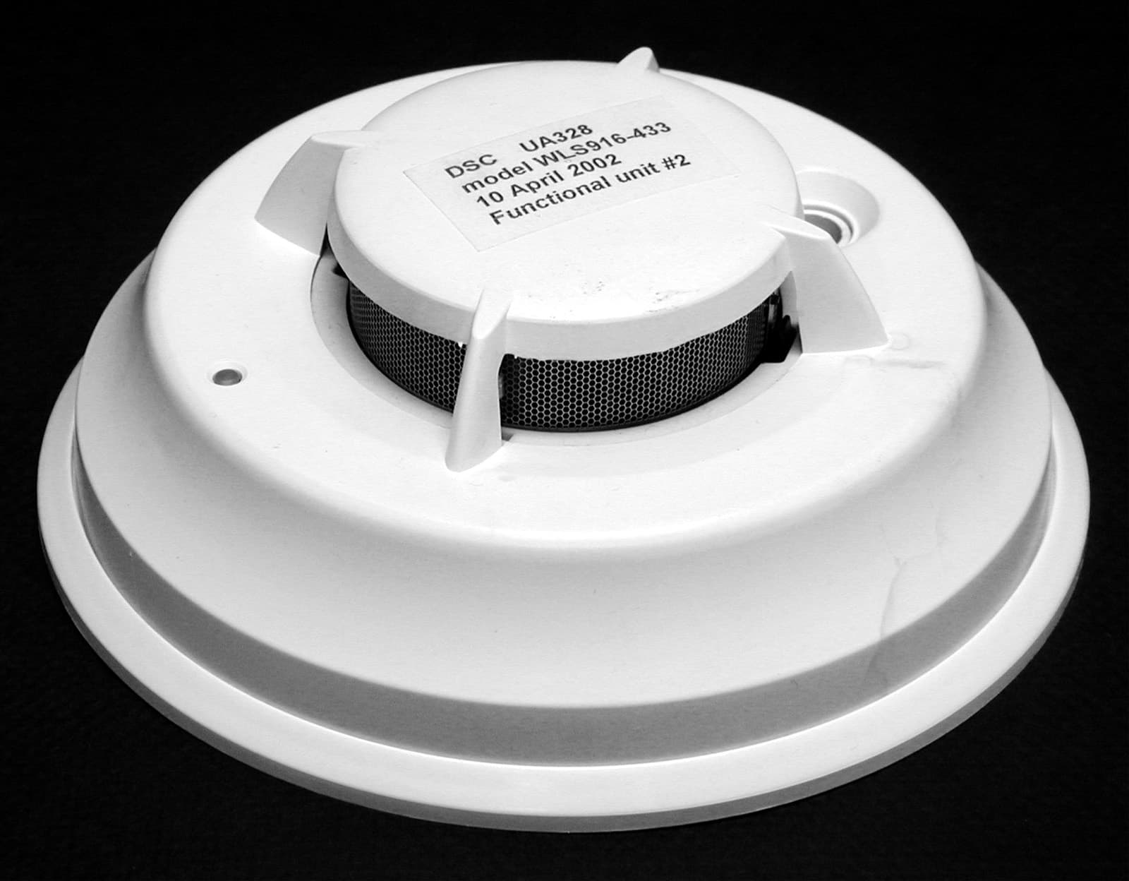
Click to zoom
Application Details
- Equipment Class
- DSC - Part 15 Security/Remote Control Transmitter
- Date of Grant
- Jun 11, 2002
- Application Purpose
- Original Equipment
- Date of Application
- Jun 11, 2002
- Equipment Note
- Smoke Detector
- Frequency Range
- 433.92000000 - 433.92000000
- Country
- Canada
Documents & Files
Document Text
Text extracted from the exhibit documents filed with the FCC. Open a document above to read the original.
Users Manual
WLS916-433 Series Wireless Smoke Detector Installation and Operating Instructions Read this instruction sheet thoroughly before installation and use of the WLS916-433 Wireless Smoke Detector Introduction The WLS916-433 is a wireless photoelectric smoke detector with a fixed temperature heat detector and an internal piezoelectric alarm. Three version are available: US version (UL), Canadian ver- sion (ULC) and an International version (EU). Operation Approximately every 7 to 8 seconds the unit tests for a smoke or heat alarm condition. During this sequence the unit also performs self diagnostics, and checks for tampers and faults. During normal operation the LED will flash every 48 seconds and the sounder will not sound. Smoke Alarm The smoke detector has a nominal fixed alarm sensitivity of approximately 2.5%/ft. obscuration. The smoke detector will go into alarm when the signal level exceeds the 'alarm' threshold and automatically restore when the signal level falls below the alarm 'restore' threshold. During an alarm the LED will flash 1/second and the sounder will sound the the evacuation temporal pattern (UL, EU) or continuous beeps (ULC). The smoke detector has a preset warning threshold at 75% of the alarm threshold. If the signal level stays above this threshold, but below the alarm threshold, for more than 120 seconds, the detec- tor will go into the 'warning' state. If the signal level falls below the early warning 'restore' threshold, the detector will restore to its normal state automatically. If the signal level rises above the alarm threshold, the detector will go into alarm. The LED will flash and the sounder will chirp every 48 seconds when in the warning state. LED/Test Butto n Piezo Sounder Alignment Marks Note: This feature is intended to provide a warning if the environ- ment is persistently close to the alarm threshold and provide more time to investigate and either escape or correct the situation. Smoke - Drift Compensation The detector automatically compensates for long-term environ- mentally induced changes to maintain a constant smoke sensitivity. When the drift compensation has reached its high or low limit of adjustment, the detector will go into the trouble state. Heat Alarm The heat detector will go into alarm when the heat signal level exceeds the heat alarm threshold (135ºF/57.22ºC); and will auto- matically restore when the heat signal level falls below the heat alarm threshold (restore). During an alarm the LED will flash 1/sec- ond and the sounder will sound the the evacuation temporal pat- tern (UL, EU) or continuous beeps (ULC). Batteries The WLS916-433 is powered by two, 3 V DC lithium batteries. Do NOT use batteries other than those listed. The low battery threshold is set so that the batteries will provide not less than 14 days of operation and at that point the detector will send a 'low battery' signal. If the battery is still low 7 days after falling through the low battery threshold, the horn will 'chirp' once every 48 seconds until battery failure. During the first 7 days after low battery detection, (non-chirp period), if the detector is tested or goes into alarm, the horn will 'chirp' once the test or alarm is restored and remain 'chirping' until battery failure. Tamper The removal of the detector from the mounting plate initiates a 'tamper' transmission. The tamper condition is restored after the detector is mounted on the plate. Wireless Transmissions A supervisory message is transmitted at 64 minute intervals (12 minutes in EU models) to the control panel. If the signal is not received the control panel determines that the detector is missing. The detector transmits the following: •Alarm / Alarm Restore - (heat or smoke alarm). Transmitted at time of occurrence. •Tamper / Tamper Restore - (tamper switch activated) 10 second maximum delay on restore before transmission. •Low Battery - (battery voltage falls below threshold). The batteries are tested & transmitted at the time of a supervisory or other transmissions. •Trouble - (detector fault or sensor compensation limit reached). Troubles are transmitted at the time of occurrence (one trouble per supervisory interval). D R A F T Installation Instructions 1 Smoke Detector Placement On smooth ceilings, detectors may be spaced 9.1M (30 feet) apart as a guide. Other spacing may be required depending on ceiling height, air movement, the presence of joists, uninsulated ceilings, etc. Consult National Fire Alarm Code NFPA 72, CAN/ULS-S553- M86 or other appropriate national standards for installation rec- ommendations. Do NOT locate smoke detectors at the top of peaked or gabled ceilings; the dead air space in these locations may prevent the unit from detecting smoke. Avoid areas with turbulent air flow, such as near doors, fans or windows. Rapid air movement around the detector may prevent smoke from entering the unit. Do NOT locate detectors in areas of high humidity. Do NOT locate detectors in areas where the temperature rises above 38ºC (100ºF) or falls below 5ºC (41ºF). Install Smoke detectors in accordance with paragraph 2.1.1.1 of NFPA 72, Chapter 2. “2-2.1.1.1 Smoke detectors shall be installed outside of each sleeping area in the immediate vicinity of the bedrooms and on each additional story of the family living unit, including basements and excluding crawl spaces and unfinished attics. In new construction, a smoke detector also shall be installed in each sleeping room.” 2 Mount Smoke Detector Backplate Secure backplate to the mounting surface using the screws provided. Note: Avoid mounting on uneven sur- faces or electrical boxes. Warping of the backplate can result in a tamper. 2 Install Batteries Install batteries in the sequence indi- cated. Use only 3 V DC CR123A batter- ies from the following approved sources: •Tekcell •Ever Ready •Panasonic Mounting Holes Locking Ta b Insert First Insert Last 4 Test Unit The test can be initiated by pressing the test button or activating the internal…
Text truncated - open the document above for the full version.
Cover Letter(s)
T H E A R T O F S E C U R I T Y 04/08/02 Office of Engineering & Technology Federal Communications Commission Washington, D.C. 20554 Subject: Request for continuous confidentiality of technical information per Sections 0.459 and 0.457 (d) (2) ( I) of CFR 47. FCC ID: F5302WLS916NB Dear Sir or Madam: Digital Security Controls Canada Ltd. is hereby filing this request for continuous confidentiality of the specified items submitted with the application for certification (Form731) with proposed identifier F5302WLS916NB. The technical documentation for which continuous confidentiality is sought is: (1) Schematic diagrams: (2) Block Diagram This technical documentation is a part of the material supporting the Form 731 application for certification, which this request for confidentiality accompanies. The schematic diagrams disclose proprietary information and technical data which Digital Security Controls Ltd. would guard from its competitors and would not make available to the public. This proprietary information constitutes a trade secret and is not a part of the product documentation that would be made available to the customers of Digital Security Controls Ltd. It would be potentially injurious to Digital Security Controls Ltd. and to its investment in the development of this innovative proprietary product to make available for public disclosure the trade secret technical information specified in this request. If there are any questions about this request for continuous confidentiality regarding trade secrets and proprietary information embodied in the technical documentation filed in support of this Form 731 application, then please contact me via our toll-free telephone number. Yours truly, Kevin Harris Approval Services Manager 905-760-3000 Ext. 2378 Email: [email protected]
ID Label/Location Info
T H E A R T O F S E C U R I T Y 04/08/02 Label Format and Location Diagram WLS916-433 The label has the dimensions: 2 by 1 in. and it will be applied on the rear cover cover. Label placement diagram: rear side of the enclosure FCC ID: F5302WLS916NB Model: WLS916-433Digital Security Controls Ltd. This device complies with Part 15 of the FCC Rules. Operation is subject to the following two conditions: (1) This device may not cause harmful interference, and (2) This device must accept any interference received, including interference that may cause undesired operation This Class B digital apparatus meets all requirements of the ICES-003. Cet appareil numerique de la classe B respecte toutes les exigence du ICES-003. IC: 160A-WLS916NB MADE IN CANADA180xxxxx FCC LABEL
Operational Description
1 THEORY OF OPERATION DSC Model Series WLS916-433 February 2002 The Model Series WLS916-433 are RF wireless photoelectric smoke detectors intended for use with a compatible DSC control panel. The photoelectric detectors detect infrared light scattered by smoke particles. An infrared light emitting diode (IRED) is pulsed periodically in an optical chamber in which a photodiode is placed so that no direct radiation is sensed from the IRED. Normally, a small level of reflected light is sensed under non-smoke conditions. When smoke enters the chamber, the pulsed IR light is scattered by the smoke particles and detected at the photodiode. When this increased smoke scattered signal reaches a predetermined threshold, the detector sends an alarm signal to the control panel. When smoke clears, the unit automatically resets to the normal condition. An available option is a 135°F fixed temperature alarm. A pair of thermistor sensors activate the unit to send an alarm signal to the control panel for high temperature. The heat alarm will reset automatically when the alarm conditions are clear. Another option is a piezo sounder, providing audible alarm and trouble annunciation. Every WLS916-433 unit is factory programmed with a serial number to be transmitted to the control panel along with its status. Once the detector is enrolled, the communication link with the control panel is supervised. The control panel monitors the transmitted data for alarm, trouble, low battery and tamper conditions. If any of these events occur or communication is lost, the system will respond with an alarm or warning annunciation. A series pair of CR123A lithium cells power the detector. The battery contact arrangement prevents reverse connection to the circuit. In case the contacts are bent to make a reverse connection, input diode D9 conducts to prevent damage to the detector circuits. Capacitor C1 filters the input voltage. The 3.0VDC regulator for VCC to microprocessor and RF circuits consists of U1, with C3 and C4 filtering the output. The microprocessor U2, controls the operation of the detector. The oscillator circuit consisting of XTL1, R42, C17, C19, and VC1 produces a tuned 6.78MHz clock, also used as a frequency reference (REFREQ) for the RF transmitter circuit. Battery power is conserved by keeping U2 in sleep mode most of the time. The circuit of Q17, R64, R65 and C30 is an RC wake-up timer connected to the IRQ input of U2. The timer period is approximately 8s and it is reset by pulsing the PTA0 output to C30. Connections to CON1, R43, R44, R45, R46 are used by factory test equipment to program the FLASH memory of U2 and select factory test modes of operation. 2 After every six wake-up intervals (48s), red LED1 flashes if there are no trouble conditions. U2 output PTA3 is pulsed rapidly 85 times during a 9ms flash duration. The circuit of Q3, R6, R7, R66, C8 produces short pulses of about 40mA through the LED that average over the flash duration to about 1mA. The pulsed light is perceived by the human eye as being much brighter than a simple 1mA pulse, and U2 encodes measurement information in the pulsing for test purposes. When operated, reed switch SW1 or pushbutton SW2 applies power to R9, R10, Q4, R8 to pull down U2 input PTA2 and activate a smoke sensor test. Protection from ESD is provided by SG3, D4. Tamper switch SW3 is normally held closed when the detector is on the mounting plate. When SW3 is released, R11 turns on Q5, R12 to pull down U2 input PTA1 and activate a tamper transmission. Protection from ESD is provided by SG4, D5. The low battery detection circuit consists of Q6, Q7, R15, R16, R17, R18 and R19. It is enabled by output PTA4, and the voltage at the divider R18, R19 is measured by the A/D converter input PTD3. The battery is tested under load at the start of each RF transmission. When the batteries are below the low battery warning threshold, U2 will send low battery status to the control panel. If the piezo sounder option is included and the battery is not replaced, a low battery warning chirp every 48s begins after 7 days or immediately after an alarm. To achieve the required sound level at a low battery voltage, a switching power supply is used to boost the supply voltage to the piezo horn driver. U2 output PTD5 pulses to C5, D1, R3, Q2, L3 produce higher voltage pulses coupled through C6, rectified by D2 and filtered by C7 at the power pin of the driver circuit U5. Feedback through R5, R4, Q1 limits the voltage by suppressing pulses at the base of Q2. U2 output PTD0 to R30, Q13, R14 applies a 3KHz square wave to the input of the driver. The circuit is protected from ESD damage by D10 and spark gaps SG5, SG6, SG7. U2 controls the communication with the control panel. It sends periodic supervisory messages and event triggered transmissions to the control panel. Outputs PTB7 and PTB6 enable and modulate the RF transmitter circuit consisting of U3 and the associated components on page 3 of the schematic diagram. A copper trace around the perimeter of the PCB forms the transmitter antenna. U2 performs the smoke detection circuit timing, measurements and IRED driver pulse level control. Output PTD4 is a factory calibrated PWM (pulse width modulation) signal, filtered by R34, C11 to produce the control voltage for the IRED D12. When enabled by a pulse at output PTD2 to R35, the emitter follower circuits of Q12, Q14 apply a controlled voltage across R48 that determines the emitter current of Q14. The slightly lower collector current of Q14 is the IRED current that determines the intensity of the IR light pulse in the smoke sensor. The IRED pulse current is nominally 75mA. U2 output PTD7 controls the power of the photodiode amplifier circuit via the R31, C13 filter. The emitter-base voltage of Q16 provides an analog ground reference of about 1V, filtered by R37, C49. The reference voltage is measured at A/D input PTD1. Reference changes resulting from the temperature coefficient of Q16 are use…
Text truncated - open the document above for the full version.
Test Report
Master:PT15231 Date: February 25, 2001 Test Report:2W06001 Applicant:Digital Security Controls Ltd. 3301 Langstaff Road Vaughan, Ontario L4K 4L2 Equipment Under Test:WLS 916-433 (EUT)433MHz Wireless Smoke Alarm In Accordance With:FCC Part 15, Subpart C For Low Power Transmitters Operating Periodically In The Band 40.66 - 40.77 MHz And Above 70 MHz Tested By:Nemko Canada Inc. 303 River Road, R.R. 5 Ottawa, Ontario K1V 1H2 Authorized By: J. Harrington, RF Group Manager Date:13 May 2002 Total Number of Pages:21 Nemko Canada Inc.FCC PART 15, SUBPART C FOR LOW POWER TRANSMITTERS PROJECT NO.: 2W06001 EQUIPMENT: WLS 916, 433MHz Smoke Alarm Page 2of 21 Table of Contents Section 1. Summary of Test Results......................................................................................3 Section 2. Equipment Under Test (EUT)..............................................................................5 Section 3. Transmission Requirements...............................................................................10 Section 4. Radiated Emissions.............................................................................................14 Section 5. Occupied Bandwidth..........................................................................................17 Section 6. Block Diagrams...................................................................................................19 Section 7. Test Equipment List...........................................................................................21 Nemko Canada Inc.FCC PART 15, SUBPART C FOR LOW POWER TRANSMITTERS PROJECT NO.: 2W06001 EQUIPMENT: WLS 916, 433MHz Smoke Alarm Page 3of 21 Section 1.Summary of Test Results General All measurements are traceable to national standards. These tests were conducted on a sample of the equipment for the purpose of demonstrating compliance with Part 15, Subpart C, Paragraph 15.231. All tests were conducted using measurement procedure ANSI C63.4-1992. Radiated emissions are made on an open area test site. A description of the test facility is on file with the FCC. New SubmissionProduction Unit Class II Permissive ChangePre-Production Unit DSC Equipment Code THIS TEST REPORT RELATES ONLY TO THE ITEM(S) TESTED. THE FOLLOWING DEVIATIONS FROM, ADDITIONS TO, OR EXCLUSIONS FROM THE TEST SPECIFICATIONS HAVE BEEN MADE. See “ Summary of Test Data”. NVLAP LAB CODE: 100351-0 TESTED BY: Glen Westwell, Wireless Technologist DATE: 13 May 2002 Nemko Canada Inc. authorizes the above named company to reproduce this report provided it is reproduced in its entirety and for use by the company’s employees only. Any use which a third party makes of this report, or any reliance on or decisions to be made based on it, are the responsibility of such third parties. Nemko Canada Inc. accepts no responsibility for damages, if any, suffered by any third party as a result of decisions made or actions based on this report. This report applies only to the items tested. Nemko Canada Inc.FCC PART 15, SUBPART C FOR LOW POWER TRANSMITTERS PROJECT NO.: 2W06001 EQUIPMENT: WLS 916, 433MHz Smoke Alarm Page 4of 21 Summary Of Test Data Name of TestPara. NumberResults Transmission Requirements15.231(a)Complies Radiated Emissions15.231(b)Complies Occupied Bandwidth15.231(c)Complies Frequency Tolerance15.231(d)N/A Periodic Alternate Field Strength Requirements15.231(e)N/A Powerline Conducted Emissions15.207N/A Footnotes For N/A’s:The EUT is battery operated 433MHz Wireless Smoke Alarm. Test Conditions: IndoorTemperature:23 °C Humidity:50 % OutdoorTemperature:11 °C Humidity:53 % Nemko Canada Inc.FCC PART 15, SUBPART C FOR LOW POWER TRANSMITTERS PROJECT NO.: 2W06001 EQUIPMENT: WLS 916, 433MHz Smoke Alarm Page 5of 21 Section 2.Equipment Under Test (EUT) General Equipment Information Manufacturer: Digital Security Controls Ltd. Model No.: WLS 916-433 Serial No.: Unit#2 Date Received In Laboratory: April 11 2002 Nemko Identification No.: Item #3 Frequency Range: 433 MHz Operating Frequency(ies) of Sample: 433.92 MHz Emission Designator: 109K5L1D Supply Power Requirement: 2 x 3V Lithium Battery Duty Cycle Calculation: 20 log 11.3ms = -18.9dB. 100 ms Nemko Canada Inc.FCC PART 15, SUBPART C FOR LOW POWER TRANSMITTERS PROJECT NO.: 2W06001 EQUIPMENT: WLS 916, 433MHz Smoke Alarm Page 6of 21 Nemko Canada Inc.FCC PART 15, SUBPART C FOR LOW POWER TRANSMITTERS PROJECT NO.: 2W06001 EQUIPMENT: WLS 916, 433MHz Smoke Alarm Page 7of 21 Wide Pulse On Time Nemko Canada Inc.FCC PART 15, SUBPART C FOR LOW POWER TRANSMITTERS PROJECT NO.: 2W06001 EQUIPMENT: WLS 916, 433MHz Smoke Alarm Page 8of 21 Narrow Pulse On Time Nemko Canada Inc.FCC PART 15, SUBPART C FOR LOW POWER TRANSMITTERS PROJECT NO.: 2W06001 EQUIPMENT: WLS 916, 433MHz Smoke Alarm Page 9of 21 On Time In 100ms Nemko Canada Inc.FCC PART 15, SUBPART C FOR LOW POWER TRANSMITTERS PROJECT NO.: 2W06001 EQUIPMENT: WLS 916, 433MHz Smoke Alarm Page 10of 21 Section 3.Transmission Requirements Para. No.: 15.231(a) Test Performed By: Glen WestwellDate of Test: 9 May 2002 Minimum Standard:15.231(a) Continuous transmissions such as voice, video or data transmissions are not permitted. 15.231(a)(1) A manually operated transmitter shall employ a switch that will automatically deactivate the transmitter within not more than 5 seconds after being released. 15.231(a)(2) A transmitter activated automatically shall cease transmission within 5 seconds of activation. 15.231(a)(3) Periodic transmissions at regular pre-determined intervals are not permitted. However polling or supervisory transmissions to determine system integrity of transmitters used in security or safety applications are allowed if the periodic rate of transmission does not exceed one transmission of not more than one second duration per hour for each transmitter. 15.231(a)(4) Intentional radiators which are employed for radio control purposes during emergencies involving fire, security, and safety of life, when activated to signal an alarm, may operate during the…
Text truncated - open the document above for the full version.
Test Report
Barry Quinlan From: "Ruby Dulmage" <[email protected]> To: "Curtis-Straus TCB" <[email protected]> Sent: Wednesday, June 05, 2002 4:33 PM Sub ject: Reply - Re: Response: DSC FCC ID: F5302WLS916NB Page 1 of 2 6/12/2002 Hi Barry: This is the summary for each type of transmission: Type of Signal Duration Repetition 1. ALARM 1 data packet = 27ms 196ms (min) - 388ms (max) for 16 packets of data and after the first 16 packets are sent, one data packet every 32s (until the alarm is cleared) 2. ALARM RESTORE TAMPER TAMPER RESTORE TROUBLE 1 data packet = 27ms 196ms (min) - 388ms (max) for 16 packets of data 3. SUPERVISORY BATTERY TROUBLE 1 data packet = 27ms 64 minutes Ruby Dulmage Submissions Specialist Nemko Canada Inc. [email protected] Tel: 613-737-9680 x 232 Fax: 613-737-9691 ----- Original Message ----- From: Curtis -Straus TCB To: Ruby Dulmage Sent: June 4, 2002 1:41 PM Subject: Re: Response: DSC FCC ID: F5302WLS916NB Hi Ruby, Issue 1 and 2 have been resolved. For issue 3 please can you provide a summary document. We do not have the resource to extract the information requested. Thanks. Barry ----- Original Message ----- From: Ruby Dulmage To: Curtis -Straus TCB Sent: Monday, June 03, 2002 8:38 AM Subject: Response: DSC FCC ID: F5302WLS916NB Hi Barry: 1. See revised manual attached which includes the statement (Refer to page 4). 2. Yes, a fresh battery was used for testing. 3. Please see attached "RF software spec". I trust the above is sufficient information for you to complete this approval. Thanks, Ruby Ruby Dulmage Submissions Specialist Nemko Canada Inc. [email protected] Tel: 613-737-9680 x 232 Fax: 613-737-9691 ----- Original Message ----- From: Curtis -Straus TCB To: Ruby Dulmage Sent: May 31, 2002 8:02 PM Subject: DSC FCC ID: F5302WLS916NB Hi Ruby, We have these issues following our review of the application: 1. The users manual does not contain the 15.21 caution against modification statement. 2. Please confirm a fresh battery was used during the testing. 3. The device has seven types of transmission - alarm, alarm restore, tamper, tamper restore, low battery, trouble and supervisory. Please provide details of the duration and repetition rate of each of the types of transmission. Best regards Barry C. Quinlan Certification Manager Curtis-Straus TCB Page 2 of 2 6/12/2002
Test Setup Photos
Nemko Canada Inc.FCC PART 15, SUBPART C FOR LOW POWER TRANSMITTERS PROJECT NO.: 2W06001 EQUIPMENT: WLS 916, 433MHz Smoke Alarm Page 16of 21 Radiated Photographs (Worst Case Configuration) Front View
Contact Information
Applicant
Dan Nita(Approvals Manager)
Test Firm
Nemko Canada Inc.Stuart Beck
Technical Specifications
| # | Rule Parts | Frequency Range | Power Output |
|---|---|---|---|
| 1 | 15.231 | 433.92 MHz - 433.92 MHz | - |
Other Applications from Tyco Safety Products Canada Ltd.

F53252RFLOCK
Jun 05, 2026IQ Lock-PGP, IQ Lock Touch-PGP
Equipment Class
DTS - Digital Transmission System
F5325PGPDC9
Apr 27, 2026PowerG wireless transceiver module
Equipment Class
DSS - Part 15 Spread Spectrum Transmitter
F5325LC203424
Dec 17, 2025Dual Technology Motion Sensor
Equipment Class
FDS - Part 15 Field Disturbance SensorF5324PGPIO9
Dec 04, 2024Wireless Input / Output (I/O) w/wo contact
Equipment Class
DSS - Part 15 Spread Spectrum Transmitter
F5323PGP9934P
Jan 16, 2024Wireless Motion detector with integrated camera
Equipment Class
DSS - Part 15 Spread Spectrum Transmitter