F5302WLS925LNBWireless window/door contact
Tyco Safety Products Canada Ltd.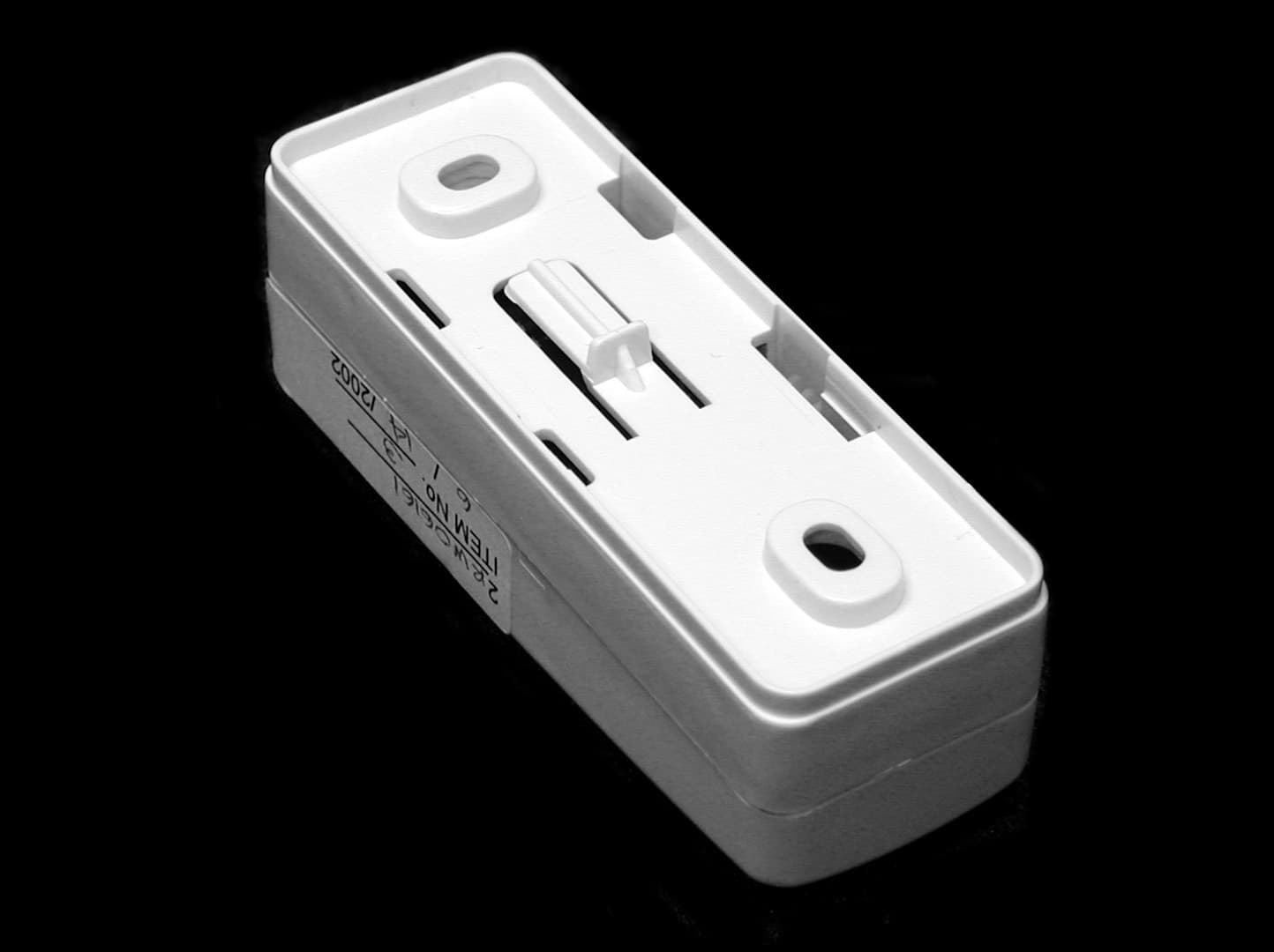
Click to zoom
Application Details
- Equipment Class
- DSC - Part 15 Security/Remote Control Transmitter
- Date of Grant
- Jul 22, 2002
- Application Purpose
- Original Equipment
- Date of Application
- Jul 22, 2002
- Equipment Note
- Wireless window/door contact
- Frequency Range
- 433.92000000 - 433.92000000
- Country
- Canada
Documents & Files
Document Text
Text extracted from the exhibit documents filed with the FCC. Open a document above to read the original.
Users Manual
WLS925L-433Mini Door/Window ContactInstallation InstructionsRemove CoverAt the notched location on the cover, insert the flat blade of a small screwdriverbetween the base and the cover and twist the screwdriver to pop the cover off.Install BatteryUse care when installing the battery and observe the correct polarity (see dia-gram below). Use only the Eveready Lithium Energizer No. EL123AP, TekcellCR123A or Panasonic Lithium CR123A battery.WARNING!: Battery may explode if mistreated. Do not recharge, disassemble or dispose of in fire. Locate TransmitterSelect the location where the transmitter is to be mounted. Perform the ModulePlacement Test to ensure that the selected location is in range of the wirelessreceiver (see receiver Installation Manual for instructions). Remove Circuit BoardBefore mounting the unit, remove the circuit board. At the notched location onthe base which is on the same side as the reed switch, insert the blade of asmall screwdriver between the base wall and the bottom of the circuit boardand pry the circuit board up.NOTE: Do not touch the coils on the circuit board as this may dam-age the unit.Mount Transmitter and MagnetMount the backplate of the transmitter using the screws provided and replacethe circuit board. The head of the screw must be below the circuit board so thatthe sensor is not shorted out. Use flat-headed screws only.Mount the magnet no more than ¼” from the transmitter. Use the spacers pro-vided. Once the unit and magnet are mounted, open and close the window/door to ensure that none of the parts interfere with this movement. Only onemagnet can be used per transmitter.Using External ContactsThe external contact terminals can be used to connect external contacts orother switches/devices to the universal transmitter. Install the additional deviceas per the manufacturer’s instruction. Connect the device to the contact termi-nals of the WLS925L-433. The input is normally closed and is not supervised.For UL installations, the wires connecting the external device to the input termi-nals must not exceed 36" (90.5 cm) in length. The contact and transmitter mustalso be in the same room.For non-UL installations, the wires connecting the external device to the inputterminals can be any length provided that the resistance of the wire does notexceed 100 Ohms. Only one contact can be used. If an external contact isused, do not install the magnet.NOTE: When installing the WLS925L-433 with the use of the externalcontact, ensure that the terminal block wiring is kept away from theantenna. WLS925L-433Contact miniature pour Porte/Fenêtre Instructions d’InstallationEnlevez le couvercleVis-à-vis l’encoche dans le couvercle, insérez la lame d’un petit tournevis plat entrela base et le couvercle et tournez le tournevis de façon à faire ouvrir le couvercle.Installez la pileInstallez minutieusement la pile en prenant soin de respecter la polarité (voir figureci-dessous). Utilisez seulement une pile de marque Eveready Lithium Energizer No.EL123AP, Tekcell CR123A ou Panasonic Lithium CR123A.AVERTISSEMENT!: La pile peut exploser si elle n’est pas utilisée cor- rectement. Ne pas recharger, démonter ou jeter au feu.Positionnez le transmetteurPlacez le transmetteur à l’endroit où vous souhaitez l’installer. Exécutez un Testd’emplacement pour vous assurer que l’endroit choisi est à l’intérieur de la portée durécepteur (pour plus de détails, référez-vous au manuel d’installation du récepteur).Retirez le circuit Avant de fixer l’unité, retirez le circuit électronique. Insérez la lame d’un petittournevis plat entre la base et le bas du circuit vis-à-vis l’encoche du côté du com-mutateur à lames. Ensuite, soulevez le circuit à l’aide du tournevis.NOTE: Ne touchez pas aux selfs sur le circuit, cela pourrait endom-mager l’unité.Fixez le transmetteur et l’aimant Fixer la plaque arrière du transmetteur avec les vis fournies et replacez le circuit.Pour éviter les courts-circuits, la tête des vis doit être plus basse que le circuit. Uti-lisez seulement des vis à tête plate.Ne fixez pas l’aimant à plus de ¼” du transmetteur. Utilisez les separateurs fournis.Une fois que l’unité et l’aimant sont installés, ouvrez et fermez la porte/fenêtrepour vous assurer qu’aucune chose n’interfère avec le mouvement. Un seul aimantpeut être utilisé par transmetteur.Usage d’un contact externeLes bornes de contact externe peuvent être utilisées pour raccorder des contacts oud’autres dispositifs externes au transmetteur universel. Installez les dispositifs addi-tionnels en suivant les instructions du fabricant. Raccordez le dispositif aux bornespour contact externe du WLS925L-433. L’entrée est normalement fermée et n’estpas supervisée.Pour les installations UL, la longueur du fil utilisé pour raccorder le dispositifexterne aux bornes d’entrée ne doit pas excéder 36" (90.5 cm). Le contact et letransmetteur doivent également être dans la même pièce. Pour les installations quine sont pas UL, le fil raccordant le dispositif aux bornes d’entrée peut être den’importe quelle longueur pourvu que la résistance du fil n’excède pas 100 Ohms.Un seul contact peut être utilisé; si un contact externe est utilisé, n’installez pasl’aimant du transmetteur.NOTE: Lorsque vous utilisez le WLS925L-433 avec un contact externe,assurez-vous d’installer le fil à l’écart de l’antenne. WLS925L-433Mini Contacto de Puerta/VentanaInstrucciones de InstalaciónRemover la CubiertaEn la ubicación dentada de la cubierta, inserte la cabeza plana de un destornilladorpequeño entre la base y la cubierta y mueva el destornillador para abrir la cubierta.Instalarla BateríaTenga cuidado cuando esté instalando la batería y observe la polaridad correcta (veael siguiente diagrama). Use solamente baterías Eveready de Litio Energizer No.EL123AP, Tekcell CR123A o Panasonic Lithium CR123A.ADVERTENCIA!: Las baterías puede explotar si son maltratada. No recar- gar, desmontar o botar en fuego.Colocar TransmisorEstablezca el lugar donde el transmisor va a ser coloca…
Text truncated - open the document above for the full version.
Cover Letter(s)
T H E A R T O F S E C U R I T Y June 14, 2002 Office of Engineering & Technology Federal Communications Commission Washington, D.C. 20554 Subject: Request for continuous confidentiality of technical information per Sections 0.459 and 0.457 (d) (2) ( I) of CFR 47. FCC ID: F5302WLS925LNB Dear Sir or Madam: Digital Security Controls Canada Ltd. is hereby filing this request for continuous confidentiality of the specified items submitted with the application for certification (Form731) with proposed identifier F5302WLS925LNB. The technical documentation for which continuous confidentiality is sought is: (1) Schematic diagrams: (2) Block Diagram This technical documentation is a part of the material supporting the Form 731 application for certification, which this request for confidentiality accompanies. The schematic diagrams disclose proprietary information and technical data which Digital Security Controls Ltd. would guard from its competitors and would not make available to the public. This proprietary information constitutes a trade secret and is not a part of the product documentation that would be made available to the customers of Digital Security Controls Ltd. It would be potentially injurious to Digital Security Controls Ltd. and to its investment in the development of this innovative proprietary product to make available for public disclosure the trade secret technical information specified in this request. If there are any questions about this request for continuous confidentiality regarding trade secrets and proprietary information embodied in the technical documentation filed in support of this Form 731 application, then please contact me via our toll-free telephone number. Yours truly, Kevin Harris Approval Services Manager 905-760-3000 Ext. 2378 Email: [email protected]
Cover Letter(s)
Barry Quinlan From: "Glen Westwell" <[email protected]> To: "Berry Quinlan" <[email protected]> Sent: Friday, July 12, 2002 8:11 AM Sub ject: Fw: Digital Security Controls FCC ID: F5302WLS925LNB Page 1 of 3 7/23/2002 Hi Barry, Here is the customer response. Please let me know if this satisfies your requirements. Glen. ----- Original Message ----- From: "Dan Nita" <[email protected] > To: "'Glen Westwell'" <[email protected] >; "Dan Nita" <[email protected] > Sent: July 12, 2002 12:00 AM Subject: RE: Digital Security Controls FCC ID: F5302WLS925LNB > Hi Glen, > > 1). This is a provision for attaching the reed relay outside the unit if > mounting of the door/window contact is not possible to be close to the > magnet (attached to the part that is moving). In a typical installation the > wires will be around 2-3 in. long. Their use will not affect the RF > characteristics of the device as measured. > > 2). yes, the open (alarm), closed (restore) and tamper conditions will all > trigger the same type of transmission, which consists of 4 rounds of same > data being transmitted. The timing is the same as the one I provided you in > the past for the WLS906 smoke detectors. We transmit 4 rounds in order to > increase the probability that the even t is being received by the alarm > receiver. > > Please let me know if more info is needed. > Regards, > Dan > > -----Original Message----- > From: Glen Westwell [mailto:[email protected]] > Sent: Thursday, July 11, 2002 1:27 PM > To: Dan Nita > Subject: Fw: Digital Security Controls FCC ID: F5302WLS925LNB > > > Hi Dan, > Please answer these questions. I may need to do some re-tests de pending > on your actual application for this device. > > Glen. > ----- Original Message ----- > From: Ruby <mailto:[email protected]> Dulmage > To: Glen Westwell - Nemko <mailto:[email protected] > > Sent: July 10, 2002 1:56 PM > Subject: Fw: Digital Security Controls FCC ID: F5302WLS925LNB > > Geln, > > Could you take care of this. > > Thanks, > Richard > > Ruby Dulmage > Submissions Specialist > Nemko Canada Inc. > [email protected] <mailto:[email protected]> > Tel: 613-737-9680 x 232 > Fax: 613-737-9691 > > ----- Original Message ----- > From: Curtis-Straus TCB <mailto:certification@curtis -straus.com> > To: Ruby Dulmage <mailto:[email protected]> > Cc: Gilles Philion <mailto:[email protected]> > Sent: July 10, 2002 12:47 PM > Subject: Digital Security Controls FCC ID: F5302WLS925LNB > > Hi Ruby, > > We have identified these issues following our review of the application: > > 1. The device appears to have connections for two wires for external input. > Please describe the wires attached to the product during test or provide and > explanation as to why no wires were attached. Provide data taken with the > wires attached if applicable. > > 2. Please confirm that "open", "closed" and "tamper" have the same > transmission characteristics. > > > Best regards > > Barry C. Quinlan > Certification Manager > Curtis-Straus TCB > Page 2 of 3 7/23/2002 > > Page 3 of 3 7/23/2002
Cover Letter(s)
Barry Quinlan From: "Glen Westwell" <[email protected]> To: "Curtis-Straus TCB" <[email protected]> Sent: Wednesday, July 17, 2002 1:25 PM Attach: 2W06161 Issue 2.pdf Sub ject: Re: Digital Security Controls FCC ID: F5302WLS925LNB Page 1 of 3 7/24/2002 Hi Barry, Thanks for your help. I have attached the Issue 2 report with wire attached data. Glen. ----- Original Message ----- From: "Curtis-Straus TCB" <certification@curtis -straus.com> To: "Glen Westwell" <[email protected]> Sent: July 15, 2002 8:07 PM Subject: Re: Digital Security Controls FCC ID: F5302WLS925LNB > Hi Glen, > > The response to issue 1 is not satisfactory. We require radiated emission > data with wires connected to the terminals. These wires should be 1 meter in > length. This is especially important with this application due to the small > margin of compliance at the fundamental. > > Barry > > ----- Original Message ----- > From: "Glen Westwell" <[email protected] > > To: "Berry Quinlan" <certification@curtis -straus.com> > Sent: Friday, July 12, 2002 5:11 AM > Subject: Fw: Digital Security Controls FCC ID: F5302WLS925LNB > > > > Hi Barry, > > Here is the customer response. Please let me know if this satisfies > your > > requirements. > > > > Glen. > > ----- Original Message ----- > > From: "Dan Nita" <[email protected] > > > To: "'Glen Westwell'" <[email protected] >; "Dan Nita" > > <[email protected] > > > Sent: July 12, 2002 12:00 AM > > Subject: RE: Digital Security Controls FCC ID: F5302WLS925LNB > > > > > > > Hi Glen, > > > > > > 1). This is a provision for attaching the reed relay outside the unit if > > > mounting of the door/window contact is not possible to be close to the > > > magnet (attached to the part that is moving). In a typical installation > > the > > > wires will be around 2-3 in. long. Their use will not affect the RF > > > characteristics of the device as measured. > > > > > > 2). yes, the open (alarm), closed (restore) and tamper conditions will > all > > > trigger the same type of transmission, which consists of 4 rounds of > same > > > data being transmitted. The timing is the same as the one I provided you > > in > > > the past for the WLS906 smoke detectors. We transmit 4 rounds in order > to > > > increase the probability that the even t is being received by the alarm > > > receiver. > > > > > > Please let me know if more info is needed. > > > Regards, > > > Dan > > > > > > -----Original Message----- > > > From: Glen Westwell [mailto:[email protected]] > > > Sent: Thursday, July 11, 2002 1:27 PM > > > To: Dan Nita > > > Subject: Fw: Digital Security Controls FCC ID: F5302WLS925LNB > > > > > > > > > Hi Dan, > > > Please answer these questions. I may need to do some re-tests > > depending > > > on your actual application for this device. > > > > > > Glen. > > > ----- Original Message ----- > > > From: Ruby <mailto:[email protected] > Dulmage > > > To: Glen Westwell - Nemko <mailto:[email protected] > > > > Sent: July 10, 2002 1:56 PM > > > Subject: Fw: Digital Security Controls FCC ID: F5302WLS925LNB > > > > > > Geln, > > > > > > Could you take care of this. Page 2 of 3 7/24/2002 > > > > > > Thanks, > > > Richard > > > > > > Ruby Dulmage > > > Submissions Specialist > > > Nemko Canada Inc. > > > [email protected] <mailto:[email protected]> > > > Tel: 613-737-9680 x 232 > > > Fax: 613-737-9691 > > > > > > ----- Original Message ----- > > > From: Curtis-Straus TCB <mailto:certification@curtis -straus.com> > > > To: Ruby Dulmage <mailto:[email protected]> > > > Cc: Gilles Philion <mailto:[email protected] > > > > Sent: July 10, 2002 12:47 PM > > > Subject: Digital Security Controls FCC ID: F5302WLS925LNB > > > > > > Hi Ruby, > > > > > > We have identified these issues following our review of the application: > > > > > > 1. The device appears to have connections for two wires for external > > input. > > > Please describe the wires attached to the product during test or provide > > and > > > explanation as to why no wires were attached. Provide data taken with > the > > > wires attached if applicable. > > > > > > 2. Please confirm that "open", "closed" and "tamper" have the same > > > transmission characteristics. > > > > > > > > > Best regards > > > > > > Barry C. Quinlan > > > Certification Manager > > > Curtis-Straus TCB > > > > > > > > > > > > > Page 3 of 3 7/24/2002
ID Label/Location Info
T H E A R T O F S E C U R I T Y June 12, 2002 Label Format and Location Diagram WLSS925L-433NA(1) The label has the dimensions: 0.5 by 2.0 in. and it will be applied on the rear cover. Label placement diagram: Rear Cover of the WLS925L-433NA(1) FCC ID: F5302WLS925LNB Model: WLS925L-433NA(1)Digital Security Controls Ltd. This device complies with Part 15 of the FCC Rules. Operation is subject to the following two conditions: (1) This device may not cause harmful interference, and (2) This device must accept any interference received, including interference that may cause undesired operation This Class B digital apparatus meets all requirements of the ICES-003. Cet appareil numerique de la classe B respecte toutes les exigence du ICES-003. IC: 160A-W925LNBMADE IN CANADA180xxxxx FCC LABEL
Test Report
Master:PT15-Sub-C-15231 Date: November 12, 2001 Test Report:2W06161 Issue 2 Applicant:Digital Security Controls Ltd. 3301 Langstaff Road Vaughan, Ontario L4K 4L2 Equipment Under Test:WLS925L-433NA (EUT)433MHz Transmitter FCC ID:F5302WLS925LNB In Accordance With:FCC Part 15, Subpart C, 15.231 Tested By:Nemko Canada Inc. 303 River Road, R.R. 5 Ottawa, Ontario K1V 1H2 Authorized By: J. Harrington, RF Group Manager Date:17 July 2002 Total Number of Pages:18 Nemko Canada Inc.FCC PART 15, SUBPART C, 15.231 PROJECT NO.:2W06161 EQUIPMENT: WLS925L-433NA Page 2 of 18 Table of Contents Section 1. Summary of Test Results......................................................................................3 Section 2. Equipment Under Test.........................................................................................5 Section 3. Transmission Requirements.................................................................................7 Section 4. Radiated Emissions.............................................................................................10 Section 5. Occupied Bandwidth..........................................................................................15 Section 6. Block Diagrams...................................................................................................17 Section 7. Test Equipment List...........................................................................................18 Nemko Canada Inc.FCC PART 15, SUBPART C, 15.231 PROJECT NO.:2W06161 EQUIPMENT: WLS925L-433NA Page 3 of 18 Section 1.Summary of Test Results General All measurements are traceable to national standards. These tests were conducted on a sample of the equipment for the purpose of demonstrating compliance with Part 15, Subpart C. All tests were conducted using measurement procedure ANSI C63.4-1992. Radiated emissions are made on an open area test site. A description of the test facility is on file with the FCC. THIS TEST REPORT RELATES ONLY TO THE ITEM(S) TESTED. THE FOLLOWING DEVIATIONS FROM, ADDITIONS TO, OR EXCLUSIONS FROM THE TEST SPECIFICATIONS HAVE BEEN MADE. See “ Summary of Test Data”. TESTED BY: ______________________________DATE: 17 July 2002 Glen Westwell, Wireless Technologist Nemko Canada Inc., a testing laboratory, is accredited by the Standards Council of Canada. The tests included in this report are within the scope of this accreditation. The results apply only to the samples tested. Nemko Canada Inc. authorizes the above named company to reproduce this report provided it is reproduced in its entirety and for use by the company’s employees only. Any use which a third party makes of this report, or any reliance on or decisions to be made based on it, are the responsibility of such third parties. Nemko Canada Inc. accepts no responsibility for damages, if any, suffered by any third party as a result of decisions made or actions based on this report. This report applies only to the items tested. Nemko Canada Inc.FCC PART 15, SUBPART C, 15.231 PROJECT NO.:2W06161 EQUIPMENT: WLS925L-433NA Page 4 of 18 Summary Of Test Data Name of TestPara. NumberResults Transmission Requirements15.231(a)Complies Radiated Emissions15.231(b)Complies Occupied Bandwidth15.231(c)Complies Frequency Tolerance15.231(d)N/A Periodic Alternate Field Strength Requirements15.231(e)N/A Powerline Conducted Emissions15.207N/A Note: This Device is powered by a 3Vdc cell only. All tests were performed with fresh batteries. Test Conditions: IndoorTemperature:20°C Humidity:42% OutdoorTemperature:25°C Humidity:46% Nemko Canada Inc.FCC PART 15, SUBPART C, 15.231 PROJECT NO.:2W06161 EQUIPMENT: WLS925L-433NA Page 5 of 18 Section 2.Equipment Under Test General Equipment Information Manufacturer: Digital Security Controls Ltd. Model No.: WLS925L-433NA Serial No.: Constant Carrier 1 Date Received In Laboratory: June 14 2002 Nemko Identification No.: #4 Transmit Frequency (Fixed):433MHz Emission Designator:278KL1D Nemko Canada Inc.FCC PART 15, SUBPART C, 15.231 PROJECT NO.:2W06161 EQUIPMENT: WLS925L-433NA Page 6 of 18 Nemko Canada Inc.FCC PART 15, SUBPART C, 15.231 PROJECT NO.:2W06161 EQUIPMENT: WLS925L-433NA Page 7 of 18 Section 3.Transmission Requirements Para. No.: 15.231(a) Test Performed By: Glen WestwellDate of Test: 25 June 2002 Minimum Standard:15.231(a) Continuous transmissions such as voice, video or data transmissions are not permitted. 15.231(a)(1) A manually operated transmitter shall employ a switch that will automatically deactivate the transmitter within not more than 5 seconds after being released. 15.231(a)(2) A transmitter activated automatically shall cease transmission within 5 seconds of activation. 15.231(a)(3) Periodic transmissions at regular pre-determined intervals are not permitted. However polling or supervisory transmissions to determine system integrity of transmitters used in security or safety applications are allowed if the periodic rate of transmission does not exceed one transmission of not more than one second duration per hour for each transmitter. 15.231(a)(4) Intentional radiators which are employed for radio control purposes during emergencies involving fire, security, and safety of life, when activated to signal an alarm, may operate during the pendency of the alarm. Test Results:Complies. Test Data:See Attached Data. Nemko Canada Inc.FCC PART 15, SUBPART C, 15.231 PROJECT NO.:2W06161 EQUIPMENT: WLS925L-433NA Page 8 of 18 Rationale for Compliance with Transmission Requirements 15.231(a)(1) : N/A 15.231(a)(2) : Transmission ceases within 2.3 seconds of activation. 15.231(a)(3) : This transmitter has no regular pre-determined periodic transmissions. 15.231(a)(4) : N/A Nemko Canada Inc.FCC PART 15, SUBPART C, 15.231 PROJECT NO.:2W06161 EQUIPMENT: WLS925L-433NA Page 9 of 18 Nemko Canada Inc.FCC PART 15, SUBPART C, 15.231 PROJECT NO.:2W06161 EQUIPMENT: WLS925L-433NA Page 10 of 18 Section 4.Radiated Emissions Para. No.: 15.231(b) Test Performed By: Glen WestwellDate of Test: …
Text truncated - open the document above for the full version.
Test Setup Photos
wireless.jpg (756x504x24b jpeg)
Contact Information
Applicant
Dan Nita(Approvals Manager)
Test Firm
Nemko Canada Inc.Stuart Beck
Technical Specifications
| # | Rule Parts | Frequency Range | Power Output |
|---|---|---|---|
| 1 | 15.231 | 433.92 MHz - 433.92 MHz | - |
Other Applications from Tyco Safety Products Canada Ltd.

F53252RFLOCK
Jun 05, 2026IQ Lock-PGP, IQ Lock Touch-PGP
Equipment Class
DTS - Digital Transmission System
F5325PGPDC9
Apr 27, 2026PowerG wireless transceiver module
Equipment Class
DSS - Part 15 Spread Spectrum Transmitter
F5325LC203424
Dec 17, 2025Dual Technology Motion Sensor
Equipment Class
FDS - Part 15 Field Disturbance SensorF5324PGPIO9
Dec 04, 2024Wireless Input / Output (I/O) w/wo contact
Equipment Class
DSS - Part 15 Spread Spectrum Transmitter
F5323PGP9934P
Jan 16, 2024Wireless Motion detector with integrated camera
Equipment Class
DSS - Part 15 Spread Spectrum Transmitter