F5303RF5108RF5108-433 Wireless Receiver
Tyco Safety Products Canada Ltd.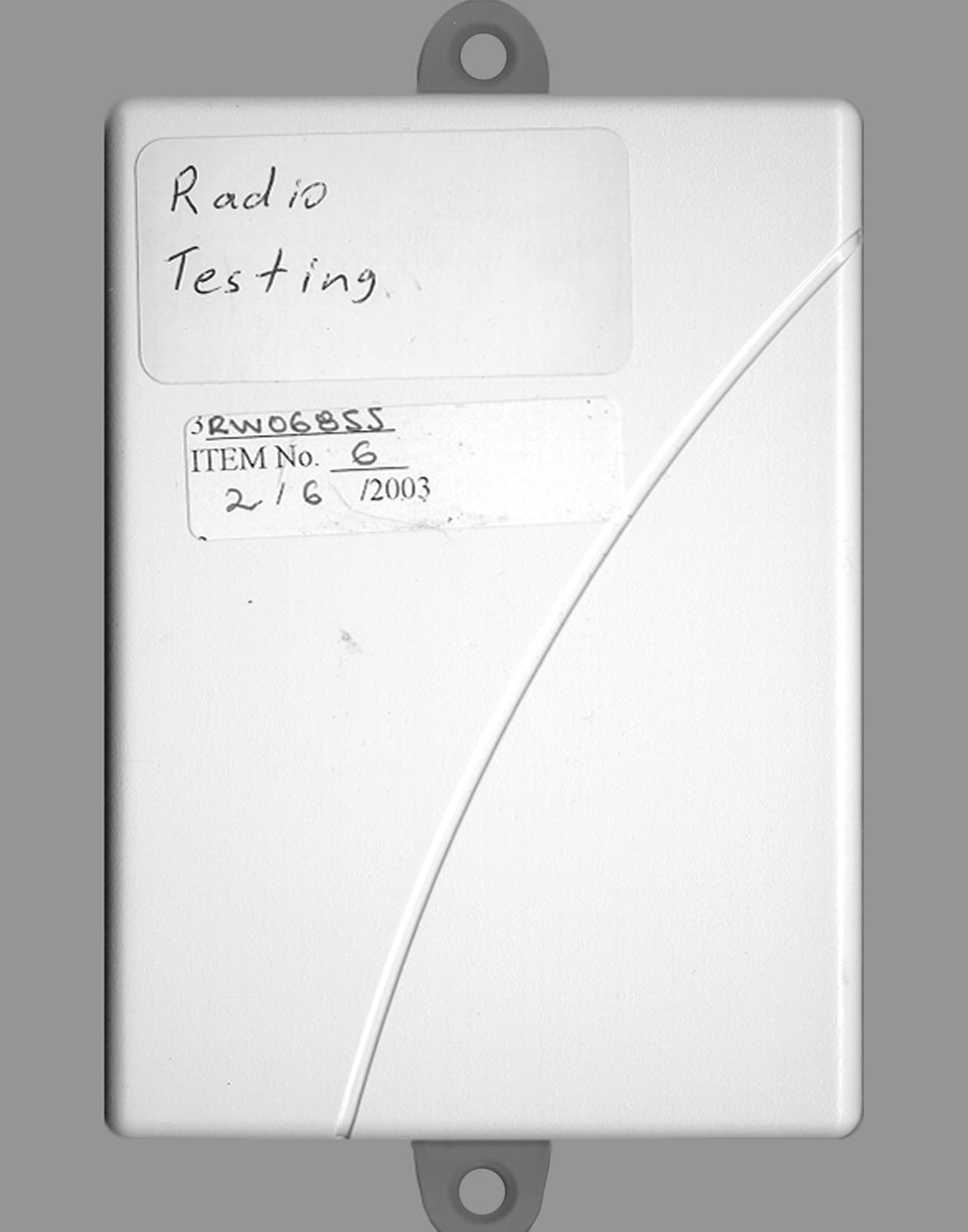
Click to zoom
Application Details
- Equipment Class
- CYY - Communications Receiver used w/Pt 15 Transmitter
- Date of Grant
- Mar 12, 2003
- Application Purpose
- Original Equipment
- Date of Application
- Mar 12, 2003
- Equipment Note
- RF5108-433 Wireless Receiver
- Frequency Range
- 433.92000000 - 433.92000000
- Country
- Canada
Documents & Files
Document Text
Text extracted from the exhibit documents filed with the FCC. Open a document above to read the original.
Users Manual
Section 1: Introduction This manual describes how to install, program and maintain the RF5108-433. Before you install the RF5108-433 module, you should have completed the following steps in your system installation: 1. Plan the installation and wiring of the security system (see your system Installation Manual ) 2. Install the control panel, and install and enroll at least one keypad to use for programming. 3. Install and enroll any hardwired zone expander modules (PC5108) you plan to use. NOTE: PC5108 zone expander modules occupy zones in 2 groups of 4 (e.g. zones 9-12 and zones 13-16). None of the zones assigned to a PC5108 module may be used for wireless devices. Program the RF5108-433 from a system keypad or using downloading software on a remote computer (e.g., DLS 2002). Read your system Installation Manual for more information. 1.1 How to use this Manual Read this manual before you begin installing the RF5108-433. To install and set up the RF5108-433 and wireless devices, follow these steps. Refer to the sections listed below. 1. Temporarily mount and wire the RF5108-433 module (see Section 2) 2. Enroll and program wireless devices (see Section 3) 3. Complete zone and other programming on the system (see Section 4) 4. Test the placement of all the wireless devices (see Section 5) 5. Permanently mount the RF5108-433 receiver and wireless devices (see Section 5) For additional information on trouble conditions, RF jamming signal detection and battery replacement, see Section 6. For help with troubleshooting, see Section 7. RF5108-433 v1.0 Installation Manual WARNING: This manual contains information on limitations regarding product use and function and information on the limitations as to liability of the manufacturer. Thank you for purchasing the RF5108-433 Wireless Receiver. This product is the result of several years of development and will allow you to connect up to 8 wireless detection devices to the PC580, PC585, PC1555, PC1565, and the Power Series control panels. The RF5108-433 operates at 433 MHz. It provides several advantages: • supervisory transmissions are sent every 64 minutes at fixed time intervals for NA version, 12 minutes for the EU version. • programmable supervisory window can be as long as 24 hours • diversity antenna arrangement for better RF reception • 2 PGM Outputs In addition, the RF5108-433 features: •6 digit serial numbers for all wireless devices: These new serial numbers include hexadecimal digits. Please read Section 3.1 “A note on Electronic Serial Numbers (ESN)” for more information on enrolling 6-digit devices. We are confident you will find the RF5108-433 Wireless Receiver a unique and useful control panel enhancement. 2 1.2 Specifications and Features • Current Draw: 40mA • Frequency: 433 MHz • Zones - receiver can receive signals from up to 8 wireless zones and 8 wireless keys • Internal antenna • PGM Outputs: 2 Open-collector PGM outputs • Supervisory - programmable supervisory window, 4 - 24 hours, in 15 minute increments • Location - can be wired up to 750 ft. / 230 m from the main panel with 22 gauge wire; the wiring used in this circuit connection must be insulated with PVC, TFE, PTFE, FEP, Neoprene or Polymide - connects to Keybus - for longer wire runs, thicker gauge wire must be used. • Compatibility: The RF5108-433 v1.x can be connected to the following panels: PC5020, PC501X, PC1555, PC1565, PC580, PC585 1.3 Compatible Wireless Devices Please refer to the Instruction sheets of the following devices for more information. The RF5108-433 v1.0 can receive signals from the following devices: • WLS904L-433 Motion Detector• WLS912L-433 Glass Break Detector • WLS904PL-433 Pet Immune PIR• WLS914 Pet Immune PIR • WLS906-433 Smoke Detector• WLS918-433 Panic Pendant • WLS907-433 Universal Transmitter• WLS919-433 Wireless Key • WLS907T-433 Low Temperature Sensor•WLS925L-433 Mini Door/Window Contact • WLS909-433 Wireless Key 1.4 DLS Compatibility The RF5108-433 can support up to 8 wireless devices that can be assigned to any of zones 1 to 32 or RF Jam Zone. If the DLS user enters valid serial numbers for more than 8 wireless devices and the wireless device serial numbers are downloaded, the RF5108-433 will accept the serial numbers of the first 8 wireless devices (in order, starting with the lowest zone number). 1.5 Batteries The wireless devices are designed to use only specific brands and types of batteries. Please see the appropriate instruction sheet for detailed information on the battery brands and types. NOTE: Do not use brands of batteries other than those specified. Using any other brand may affect system operation. Section 2: RF5108-433 Set up & Wiring This section describes how to set up and wire the RF5108-433 module. 2.1 Unpack the RF5108-433 Check that the following parts are in your RF5108-433 package: • 1 WLS919-433 wireless key • RF5108-433 in cabinet • Hardware for mounting the cabinet • LED indicator plate I N T R O D U C T I O N 3 2.2 Choose a Mounting Location for the RF5108-433 NOTE: Mount the RF5108-433 receiver and wireless devices after you have done place- ment tests with the wireless devices (see sections 5.1 and 5.2). Find a place that is: • Dry • Central to the proposed placement of all wireless devices • As high as possible • Far from sources of interference, including: electrical noise such as computers, televisions and electric motors in appliances and heating and air conditioning units; large metal objects like heating ducts and plumbing which may shield the antenna. Ensure the electrical wires will not run over the antenna(s) of the module when it is mounted. NOTE: When mounting the RF5108-433 in a basement, place the module as high and as close to the underside of the first floor as possible. The range of the module will be re- duced if the unit is mounted below ground level. 2.3 Antennas The antennas have been installed at the factory. CAUTION!: Do not attempt to touch or adjust the antennas. 2.4 PC5320 Compatibil…
Text truncated - open the document above for the full version.
Cover Letter(s)
T H E A R T O F S E C U R I T Y 02/05/03 Office of Engineering & Technology Federal Communications Commission Washington, D.C. 20554 Subject: Request for continuous confidentiality of technical information per Sections 0.459 and 0.457 (d) (2) ( I) of CFR 47. FCC ID: F5303RF5108 Dear Sir or Madam: Digital Security Controls Canada Ltd. is hereby filing this request for continuous confidentiality of the specified items submitted with the application for certification (Form731) with proposed identifier F5303RF5108 The technical documentation for which continuous confidentiality is sought is: (1) Schematic & PCB diagrams: (2) Block Diagram This technical documentation is a part of the material supporting the Form 731 application for certification, which this request for confidentiality accompanies. The schematic diagrams disclose proprietary information and technical data which Digital Security Controls Ltd. would guard from its competitors and would not make available to the public. This proprietary information constitutes a trade secret and is not a part of the product documentation that would be made available to the customers of Digital Security Controls Ltd. It would be potentially injurious to Digital Security Controls Ltd. and to its investment in the development of this innovative proprietary product to make available for public disclosure the trade secret technical information specified in this request. If there are any questions about this request for continuous confidentiality regarding trade secrets and proprietary information embodied in the technical documentation filed in support of this Form 731 application, then please contact me via our toll-free telephone number. Yours truly, Kevin Harris Approval Services Manager 905-760-3000 Ext. 2378 Email: [email protected]
Cover Letter(s)
From: "Ruby Dulmage" <[email protected]> To: "Curtis-Straus Certification Dept." <[email protected]> Sent: Friday, February 28, 2003 1:56 PM Attach: 3W06855-2.pdf Sub ject: Re: Revised test report - Digital Security Controls FCC ID: F5303RF5108 Page 1 of 1 3/12/2003 Hi Barry: See attached revised test report which also contains the calibration dates for the test equipment. Thanks and have a good weekend. Ruby ----- Original Message ----- From: Curtis -Straus Certification Dept. To: Ruby Dulmage Sent: Friday, February 21, 2003 6:00 PM Subject: Digital Security Controls FCC ID: F5303RF5108 Hi Ruby, Our reviewers have identified these issues: 1. It appears the radiated measurements were taken without all of the ports being populated with the appropriate cables. Please supply a revised test report. 2. Please provide the calibration dates for the test equipment. Best regards Barry C. Quinlan Certification Manager Curtis-Straus TCB
ID Label/Location Info
Side of the unit showing placement of label (Actual size) Digital Security Controls Ltd. ISO9001 Registered 3301 Langstaff Road, Concord Ontario, Canada L4K 4L2 Phone: 905-760-3000 Toll Free: 1-888-888-7838 Fax: 905-760-3030 ® RF5108-433Digital Security Controls Ltd. This device complies with Part 15 of the FCC Rules. Operation is sub- ject to the following two conditions: (1) This device may not cause harm- ful interference, and (2) this device must accept any interference re- ceived, including interference that may cause undesired operation. FCC ID:F5303RF5108 IC: 160A-RF5108 MADE IN CANADA18011216 Rev 001 This Class B digital apparatus meets all requirements of the ICES-003. Cet appareil numérique de la classe B respecte toutes les exigences du ICES-003. 18011216 Rev 001 RF5108-433 FCC/IC LABELING File: [18011216_REV_001_RF5108-433_FCC-IC_LB_MYLAR.cdr] Dashed line indicates cut edge of label Label to be printed on self-adhesive Mylar Label shown actual size Label shown 250% of actual size 35 mm 12.7 mm RF5108-433Digital Security Controls Ltd. This device complies with Part 15 of the FCC Rules. Operation is sub- ject to the following two conditions: (1) This device may not cause harm- ful interference, and (2) this device must accept any interference re- ceived, including interference that may cause undesired operation. FCC ID:F5303RF5108 IC: 160A-RF5108 MADE IN CANADA18011216 Rev 001 This Class B digital apparatus meets all requirements of the ICES-003. Cet appareil numérique de la classe B respecte toutes les exigences du ICES-003. RF5108-433Digital Security Controls Ltd. This device complies with Part 15 of the FCC Rules. Operation is sub- ject to the following two conditions: (1) This device may not cause harm- ful interference, and (2) this device must accept any interference re- ceived, including interference that may cause undesired operation. FCC ID:F5303RF5108 IC: 160A-RF5108 MADE IN CANADA18011216 Rev 001 This Class B digital apparatus meets all requirements of the ICES-003. Cet appareil numérique de la classe B respecte toutes les exigences du ICES-003.
Operational Description
CIRCUIT DESCRIPTION Device: Narrow Band Receiver Model: RF5108 -433 ETSI Identifier: Schematic Diagram: see UA634_REVB_SCH.pdf Description: This device is a narrow band ASK receiver for 433.92MHz. It receives signals in the area covered, demodulates the signals then sends them to the control unit of the wireless security system. The unit consists of two main circuit sections, a control section with a microprocessor (ST72F324) and an ASK receiver (TDA5200). ASK Receiver: The antenna receives the incoming signals and feeds them to the front RF amplifier and LNA of TDA5200 to achieve good sensitivity and selectivity. The mixer mixes signals from LNA and the VCO. The reference frequency of 6.6128125MHz for the PLL is provided by the control section to lock the free running VCO to 423.22MHz. After mixing, an IF filter passes the desired signals to the IF amplifier and the demodulator. The demodulated signal then is sent to the control unit for further processing. The Control Section: This section provides the reference frequency and the channel enable signals to switch antennas. It also controls the activities of the Keybus interface. Abbreviations: LNA = Low Noise Amplifier PLL = Phase Locked Loop IF = Intermediate Frequency VCO = Voltage Controlled Oscillator
Test Report
Master: PT15-SubB-15109 Date: October 17, 2001 Test Report:3W06855.2 Applicant:Digital Security Controls Ltd. 3301 Langstaff Road Vaughan Ont., L4K 4L2 Equipment Under Test:RF5108 433MHz Wireless Receiver (EUT) In Accordance With:FCC Part 15, Subpart B, 15.109 Tested By:Nemko Canada Inc. 303 River Road, R.R. 5 Ottawa, Ontario K1V 1H2 Authorized By:Kevin Carr, EMC Specialist Date:28 February 2003 Total Number of Pages:10 Nemko Canada Inc.FCC PART 15, SUBPART B, 15.109 PROJECT NO.: 3W06855.2 EQUIPMENT: RF5108 Wireless Receiver Page 2 of 10 Table Of Contents Section 1. Summary of Test Results......................................................................................3 Section 2. General Equipment Specification........................................................................5 Section 3. Radiated Emissions...............................................................................................7 Section 4. Block Diagrams.....................................................................................................9 Section 5. Test Equipment List...........................................................................................10 Nemko Canada Inc.FCC PART 15, SUBPART B, 15.109 PROJECT NO.: 3W06855.2 EQUIPMENT: RF5108 Wireless Receiver Page 3 of 10 Section 1.Summary of Test Results General All measurements are traceable to national standards. These tests were conducted on a sample of the equipment for the purpose of demonstrating compliance with FCC Part 15, Subpart B. Measurement procedure ANSI C63.4-2000 was used for all tests. Radiated Emissions were measured on an open area test site. A description of the test facility is on file with the FCC. THIS TEST REPORT RELATES ONLY TO THE ITEM(S) TESTED. THE FOLLOWING DEVIATIONS FROM, ADDITIONS TO, OR EXCLUSIONS FROM THE TEST SPECIFICATIONS HAVE BEEN MADE. See “ Summary of Test Data”. TESTED BY: _______________________________ DATE: 12 February 2003 Glen Westwell, Wireless Technologist Nemko Canada Inc. authorizes the above named company to reproduce this report provided it is reproduced in its entirety and for use by the company’s employees only. Any use which a third party makes of this report, or any reliance on or decisions to be made based on it, are the responsibility of such third parties. Nemko Canada Inc. accepts no responsibility for damages, if any, suffered by any third party as a result of decisions made or actions based on this report. This report applies only to the items tested. Nemko Canada Inc.FCC PART 15, SUBPART B, 15.109 PROJECT NO.: 3W06855.2 EQUIPMENT: RF5108 Wireless Receiver Page 4 of 10 Summary Of Test Data Name Of TestPara. No.Results Radiated Emissions15.109Complies Powerline Conducted Emissions15.107N/A Test Conditions: IndoorTemperature:21?C Humidity:38% OutdoorTemperature:-15?C Humidity:15% Nemko Canada Inc.FCC PART 15, SUBPART B, 15.109 PROJECT NO.: 3W06855.2 EQUIPMENT: RF5108 Wireless Receiver Page 5 of 10 Section 2.General Equipment Specification Manufacturer: Digital Security Controls Ltd. Equipment: 433MHz Wireless Receiver Model No.: RF5108 Serial No.: None Date Received In Laboratory: Feb 6, 2003 Nemko Identification No.: 6 Receive Frequency: 433.92MHz Receive L.O.: 423.22MHz Nemko Canada Inc.FCC PART 15, SUBPART B, 15.109 PROJECT NO.: 3W06855.2 EQUIPMENT: RF5108 Wireless Receiver Page 6 of 10 Test Arrangement Client supplied Test Set-up. Please give a diagram of your proposed test arrangement detailing where appropriate earthing, cable types and lengths, drive equipment and any test software necessary. Software Version used during testing was Version 1.0 Test Arrangement Diagram : EUT Ports:Cable Details:Support Equipment Details: 1.RedAWG2212Vdc 2.BlkAWG22Gnd 3.AWG221 meter each. 4. 5. RF5108 (Wireless Receiver) Red Blk Yl Grn PGM1 PGM2 12Vdc Nemko Canada Inc.FCC PART 15, SUBPART B, 15.109 PROJECT NO.: 3W06855.2 EQUIPMENT: RF5108 Wireless Receiver Page 7 of 10 Section 3.Radiated Emissions Para. No.: 15.109(a) Test Performed By: Glen WestwellDate of Test: Feb 28, 2003 Minimum Standard: Frequency(MHz)Field Strength (dB?V/m @ 3m) 30 - 8840.0 88 - 21643.5 216 - 96046.0 Above 96054.0 Test Results:Complies Measurement Data:No emissions detected. All emissions were searched on three orthogonal axis. No emissions within 20dB of the limit were detected. The receiver was cohered using a 433.92MHz signal source. The DC source was varied +/- 15% of the nominal input voltage to verify worst case emissions. Nemko Canada Inc.FCC PART 15, SUBPART B, 15.109 PROJECT NO.: 3W06855.2 EQUIPMENT: RF5108 Wireless Receiver Page 8 of 10 Pre-Scan Set Up Photo Open Area Test Site Radiated Emissions Photo Nemko Canada Inc.FCC PART 15, SUBPART B, 15.109 PROJECT NO.: 3W06855.2 EQUIPMENT: RF5108 Wireless Receiver Page 9 of 10 Section 4.Block Diagrams Outdoor Test Site For Radiated Emissions Radiated Prescan SPECTRUM ANALYZER AND PLOTTER OR TEST RECEIVER COMPUTER ANTENNA EUT SHIELDED ROOM 3 METERS EUT NON-CONDUCTING TURN-TABLE 0.8 METER VARIABLE SEARCH HEIGHT (1 TO 4 m) TO TEST RECEIVER/SPECTRUM ANALYZER SEARCH ANTENNA Nemko Canada Inc.FCC PART 15, SUBPART B, 15.109 PROJECT NO.: 3W06855.2 EQUIPMENT: RF5108 Wireless Receiver Page 10 of 10 Section 5.Test Equipment List CAL CYCLE EQUIPMENTMANUFACTURERMODELSERIALLast Cal.Next Cal. 1 YearSpectrum AnalyzerHewlett Packard8565EFA00098115 Jul 0215 Jul o3 1 Year Spectrum Analyzer-1 Hewlett Packard8566B2311A0223827 Nov 0107 Mar 03 1 YearSpectrum Analyzer Display-1 Hewlett Packard8566B2314A0475927 Nov 0107 Mar 02 1 YearReceiverRohde & SchwarzESVS 30DE3551604 Jul 0204 Jul 03 1 YearHorn AntennaEMCO #23115433609 Dec 0209 Dec 03 1 YearDipole Antenna SetEMCO #23121CFA00134906 May 0206May 03 1 YearSignal GeneratorHewlett Packard8660C2044A0330413 Jan 0213 Mar 03
Test Setup Photos
Nemko Canada Inc.FCC PART 15, SUBPART B, 15.109 PROJECT NO.: 3W06855.2 EQUIPMENT: RF5108 Wireless Receiver Page 8 of 10 Pre-Scan Set Up Photo Open Area Test Site Radiated Emissions Photo
Contact Information
Applicant
Dan Nita(Approvals Manager)
Test Firm
Nemko Canada Inc.Stuart Beck
Technical Specifications
| # | Rule Parts | Frequency Range | Power Output |
|---|---|---|---|
| 1 | 15B | 433.92 MHz - 433.92 MHz | - |
Other Applications from Tyco Safety Products Canada Ltd.

F53252RFLOCK
Jun 05, 2026IQ Lock-PGP, IQ Lock Touch-PGP
Equipment Class
DTS - Digital Transmission System
F5325PGPDC9
Apr 27, 2026PowerG wireless transceiver module
Equipment Class
DSS - Part 15 Spread Spectrum Transmitter
F5325LC203424
Dec 17, 2025Dual Technology Motion Sensor
Equipment Class
FDS - Part 15 Field Disturbance SensorF5324PGPIO9
Dec 04, 2024Wireless Input / Output (I/O) w/wo contact
Equipment Class
DSS - Part 15 Spread Spectrum Transmitter
F5323PGP9934P
Jan 16, 2024Wireless Motion detector with integrated camera
Equipment Class
DSS - Part 15 Spread Spectrum Transmitter