F5304WS4945SECURITY/REMOTE CONTROL TRANSMITTER
Tyco Safety Products Canada Ltd.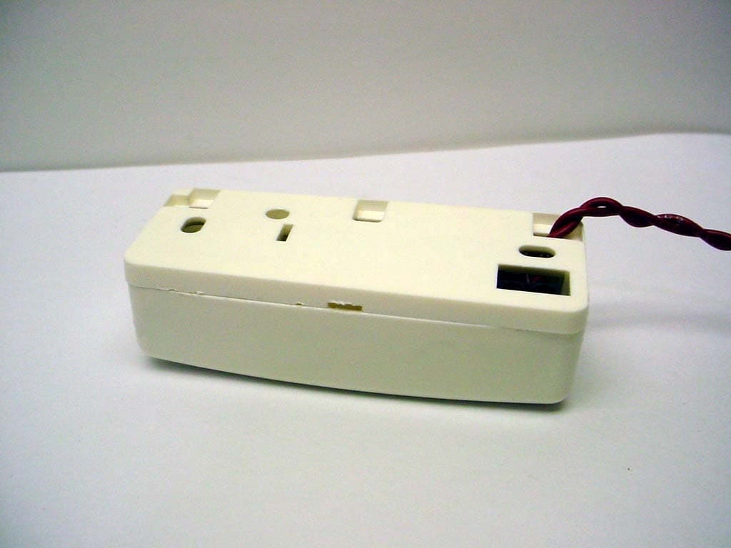
Click to zoom
Application Details
- Equipment Class
- DSC - Part 15 Security/Remote Control Transmitter
- Date of Grant
- Oct 10, 2004
- Application Purpose
- Original Equipment
- Date of Application
- Oct 10, 2004
- Equipment Note
- SECURITY/REMOTE CONTROL TRANSMITTER
- Frequency Range
- 433.92000000 - 433.92000000
- Country
- Canada
Documents & Files
Document Text
Text extracted from the exhibit documents filed with the FCC. Open a document above to read the original.
Users Manual
WS4945Wireless Door/Window ContactInstallation InstructionsPowering the WS4945Remove the battery pull-tab to power the unit. While ho lding the unit in one hand, pull out the plastic tab in the direction indicated.Locate TransmitterSelect the location where the transmitter is to be mounted. Perform the Module Placement Test to ensure thatthe selected location is in range of the wireless receiver (Figure C), see receiver Installation Manual for instructions.Enrolling a WS4945On the back of the door contact housing, there will be a 6-digit serial number. Please refer to your receiver Installation Manual for information on which serial number should be enrolled. NOTE: Test unit at least once yearly. UL Listed for residential applications. NOTE: Compatible with NT9005, PC5132(A)-433, PC4164-433, RF5108-433 and RF5501-433.Mount Transmitter and MagnetRemove the back from the transmitter. Mount the back housing of the transmitter, using the supplied screws or adhesive tape, to the desired location. NOTE: The adhesive tape is not for use in UL Installations. Align the magnet with the notched arrow on the transmitter housing (Figure B). Mount the magnet amaximum of 5/8” (1.8cm) from the transmitter by using the adhesive tape or screws and firmly pressing the unit into the desired location. If necessary, use the spacers provided. Once the transmitter and magnet are mounted, open and close the window/door to ensure that none of the parts interfere with this movement.Only one magnet can be used per transmitter.Using External ContactsCAUTION ! When wiring an external switch to the contact inputs of the WS4945 it is imperative to avoid coiling or looping extra wire inside th e transmitter housing. Wires should be clipped short and removed or pushed back through the hole in the backplate. If this is not done, the coiled wire can generate an electric field that can adversely affect the ability of the unit to transmit.The external contact terminals can be used to connect external contacts or other switches/devices to the uni-versal transmitter. Install the additional device as pe r the manufacturer’s instruction. Connect the device to the contact terminals of the WS 4945. The input is normally cl osed and is not supervised. For all installations, the wires connec ting the external device to the input terminals must not exceed 16" (40 cm) in length, provided that the resistance of the wi re does not exceed 100 Ohms. The contact and transmit- ter must also be in the same room.Only one contact can be used. If an external contact is used, do not install the magnet. Tamper SwitchThere is one tamper switch on the WS4945 board. Removing the cover or removing the unit from its mount- ing surface will cause a zone tamper (see Figure A). Replacing the BatteryTo replace the battery, insert a flathead screwdriver into either side of the unit and carefully twist to separate the top and bottom plastic (Figure A). Once separated, th e battery will be visible. Remove the old battery and wait 90 seconds before installing a new one. Warning! : Battery may explode if mistreated. Do not recharge, disassemble or dispose of in fire. WS4945Contact miniature p our Porte/Fenêtre Instructions d’InstallationMise en marche du WS4545Retirez la languette de la batterie pour mettre le dispositif sous tension. En tenant le dispositif dans une main, retirez la languette en plastique dans la direction indiquée.Positionnez le transmetteurPlacez le transmetteur à l’endroit où vo us souhaitez l’installer. Exécutez un Te st d’emplacement pour vous assurer que l’endroit choisi est à l’intérieur de la portée du récepteur (Fig . C), pour plus de détails, réfé rez-vous au manuel d’installa- tion du récepteur.Assignation d’un WS4945Il y un numéro de série à l’arrière du boîtier, de six chiffres. Consultez le ma nuel d’installation de votre récepteur pour savoir lequel doit être enregistré. NOTE: Testez le dispositif au moin s une fois par an. Homologué par UL pour les applications résidentielles. NOTE: Compatible avec le NT9005, PC5132(A)-433, PC4164-433, RF5108-433 et RF5501-433.Fixez le transmetteur et l’aimant Retirez le couvercle arrière de l'émetteur. Installez le couv ercle arrière de l'émetteur à l'endroit désiré, à l'aide des vis ou du ruban adhésif. NOTE: La ruban adhésive n'es t pas pour l'usage dans le s Installations de UL. Alignez l'aimant à la flèche entaillée sur le boîtier de l'émetteur (voir figure B). Installez l'aimant à une dis- tance maximum de 1,8cm (5/8 pouce) de l'émetteur en re tirant le dos adhésif et appuyant fermement le disposi- tif à l'endroit désiré. Si nécessaire, util isez les espaceurs fournis. Une fois que l'émetteur et l'aimant sont installés, ouvrez et fermez la fenêtre/porte afin de vous assurer que rien n'empêche leur mouvement. Un seul aimant peut être utilisé par émetteur.Usage d’un contact externeAVERTISSEMENT!: Pour le câblage d’un commutateur externe aux entrées par contact du WS4945, il est essentiel d’éviter l’enroulement ou le bouclage du câble supplémentaire à l’intérieur du coffret de l’émetteur. Les câbles doivent être coupés courts et retirés ou passés derrière le coffret par le trouse trouvant sur la plaque arrière. Si cela n’est pas fait, le câble enroulé peut créer un champ élec- trique qui pourra empêcher l’unité d’émettre correctement.Les bornes de contact externe peuvent être utilisées pour raccorder des contacts ou d’au tres dispositifs externes au transmetteur universel. Installez les dispositifs additionnels en suivant les instructions du fabricant. Raccordez ledispositif aux bornes pour contact externe du WS4945. L’entrée est normalement fermée et n’est pas supervisée. Pour tous les installations, la longueur du fil utilisé pour raccorder le dispositif externe aux bornes d’entrée ne doit pas excéder 16" (40cm), pourvu que la résistance du fi l n’excède pas 100 Ohms. Le contact et le transmetteur doivent également être dans la même pièce. Un seul contac t peut être utilisé; si un contact…
Text truncated - open the document above for the full version.
Cover Letter(s)
T H E A R T O F S E C U R I T Y 09/29/04 Office of Engineering & Technology Federal Communications Commission Washington, D.C. 20554 Subject: Request for continuous confidentiality of technical information per Sections 0.459 and 0.457 (d) (2) ( I) of CFR 47. FCC ID: F5304WS4945 Dear Sir or Madam: Digital Security Controls Canada Ltd. is hereby filing this request for continuous confidentiality of the specified items submitted with the application for certification (Form731) with proposed identifier F5304WS4945. The technical documentation for which continuous confidentiality is sought is: (1) Schematic diagrams: (2) Block Diagram This technical documentation is a part of the material supporting the Form 731 application for certification, which this request for confidentiality accompanies. The schematic diagrams disclose proprietary information and technical data which Digital Security Controls Ltd. would guard from its competitors and would not make available to the public. This proprietary information constitutes a trade secret and is not a part of the product documentation that would be made available to the customers of Digital Security Controls Ltd. It would be potentially injurious to Digital Security Controls Ltd. and to its investment in the development of this innovative proprietary product to make available for public disclosure the trade secret technical information specified in this request. If there are any questions about this request for continuous confidentiality regarding trade secrets and proprietary information embodied in the technical documentation filed in support of this Form 731 application, then please contact me via our toll-free telephone number. Yours truly, Dan Nita Approvals Manager 905-760-3000 Ext. 2706 Email: [email protected]
External Photos
ANNEX 2 – EXTERNAL PHOTOGRAPHS DIGITAL SECURITY CONTROLS LTD. Wireless Door/Window Contact, Model WS4945 FCC ID: F5304WS4945 IC: 160A-WS4945 A2 - 1 ANNEX 2 – EXTERNAL PHOTOGRAPHS DIGITAL SECURITY CONTROLS LTD. Wireless Door/Window Contact, Model WS4945 FCC ID: F5304WS4945 IC: 160A-WS4945 A2 - 2
ID Label/Location Info
WS4945 Digital Security Controls This device complies with Part 15 of the FCC Rules. Operation is sub- ject to the following two conditions: (1) This device may not cause harm- ful interference, and (2) this device must accept any interference re- ceived, including interference that may cause undesired operation. FCCID:F5304WS4945 IC: 160A-WS4945 MADE IN CANADA18011261 Rev 001 This Class B digital apparatus meets all requirements of the ICES-003. Cet appareil numérique de la classe B respecte toutes les exigences du ICES-003. FCC/ICES-003 Labeling for WS4945 Wireless Mini Door/Window Contact File: [18011261_REV_001_WS4945_FCC-IC_LB_MYLAR.cdr] Dashed line indicates cut edge of label Label to be printed on UL Approved white self-adhesive Mylar type material Indelible black ink Label shown actual size Label shown 250% of actual size 35 mm 12.7 mm Side of the unit showing placement of label (Actual size) ® WS4945 Digital Security Controls This device complies with Part 15 of the FCC Rules. Operation is sub- ject to the following two conditions: (1) This device may not cause harm- ful interference, and (2) this device must accept any interference re- ceived, including interference that may cause undesired operation. FCCID:F5304WS4945 IC: 160A-WS4945 MADE IN CANADA 18011261 Rev 001 This Class B digital apparatus meets all requirements of the ICES-003. Cet appareil numérique de la classe B respecte toutes les exigences du ICES-003. WS4945 Digital Security Controls Ltd. This device complies with Part 15 of the FCC Rules. Operation is sub- ject to the following two conditions: (1) This device may not cause harm- ful interference, and (2) this device must accept any interference re- ceived, including interference that may cause undesired operation. FCC ID:F5303WS4945 IC: 160A-WS4945 MADE IN CANADA 18011261 Rev 001 This Class B digital apparatus meets all requirements of the ICES-003. Cet appareil numérique de la classe B respecte toutes les exigences du ICES-003.
Internal Photos
ANNEX 3 – INTERNAL PHOTOGRAPHS DIGITAL SECURITY CONTROLS LTD. Wireless Door/Window Contact, Model WS4945 FCC ID: F5304WS4945 IC: 160A-WS4945 A2 - 1 ANNEX 3 – INTERNAL PHOTOGRAPHS DIGITAL SECURITY CONTROLS LTD. Wireless Door/Window Contact, Model WS4945 FCC ID: F5304WS4945 IC: 160A-WS4945 A2 - 2 ANNEX 3 – INTERNAL PHOTOGRAPHS DIGITAL SECURITY CONTROLS LTD. Wireless Door/Window Contact, Model WS4945 FCC ID: F5304WS4945 IC: 160A-WS4945 A2 - 3
Operational Description
WS4945 Functional Description WS4945 is a device, which is mounted on a doorframe. A magnet will be mounted on the door. A reed switch, which is in the device, will be closed if the magnet is in close proximity to the reed switch. When the door is opened the reed switch will open and the transmitter will send the “Open” condition. When the door is closed the reed switch will close and the transmitter will send the “Closed” condition. If the device is removed from the door, there will be a tamper transmission sent to the receiver. This is detected through a switch connected to Zone 2, which is closed when the device is mounted to the doorframe. When in the door contact configuration the ASIC will be in a sample mode. This means that the RC oscillator is running but is only incrementing a timer chain. The timer chain will wakeup the state machine once the pre- programmed number of ticks is realized. The state machine will turn on the pull up resistors and sample the inputs. If the zone has changed state and remained stable for the debounce period the state machine will power up the transmitter section, wait the VCO lock time and stabilization period and send the transmission. After the single round has been sent the state machine will load the inter-round timer and shut down. During the subsequent wake ups the state machine will check the inter-round timer and send the next round when the timer has expired. This sequence will continue until all the pre-programmed rounds have been sent. The state machine will also keep track of the supervisory timer. Under the same wake-up sequence the state machine check the supervisory timer and send the supervisory signals when required.
Test Report
Wireless Door/Window Contact Model No.: WS4945 FCC ID: F5304WS4945 Applicant: Digital Security Controls Ltd. 3301 Langstaff Road Concord, Ontario Canada, L4K 4L2 In Accordance With FEDERAL COMMUNICATIONS COMMISSION (FCC) Part 15, Subpart C, Section 15.231(a) Momentarily Operation at 433.92 MHz UltraTech's File No.: SSS-067F15C231 This Test report is Issued under the Authority of Tri M. Luu, Professional Engineer, Vice President of Engineering UltraTech Group of Labs Date: October 6, 2004 Report Prepared by: Anca Dobre Issued Date: October 6, 2004 Tested by: Hung Trinh, RFI Technician Test Dates: September 26 - 27, 2004 The results in this Test Report apply only to the sample(s) tested, and the sample tested is randomly selected. This report must not be used by the client to claim product endorsement by NVLAP or any agency of the US Government. UltraTech 3000 Bristol Circle, Oakville, Ontario, Canada, L6H 6G4 Tel.: (905) 829-1570 Fax.: (905) 829-8050 Website: www.ultratech-labs.com , Email: [email protected], Email: [email protected] 2 31040/SIT C-1376 46390-2049 200093-0 SL2-IN-E-1119R 00-034 FCC Part 15, Subpart C, Section 15.231(a) (433.92 MHz) Wireless Door/Window Contact, Model WS4945 FCC ID: F5304WS4945 ULTRATECH GROUP OF LABS File #: SSS-067F15C231 3000 Bristol Circle, Oakville, Ontario, Canada L6H 6G4 October 6, 2004 Tel. #: 905-829-1570, Fax. #: 905-829-8050, Email: [email protected] , Website: http://www.ultratech-labs.com All test results contained in this engineering test report are traceable to National Institute of Standards and Technology (NIST) TABLE OF CONTENTS EXHIBIT 1. SUBMITTAL CHECK LIST........................................................................................................................ 1 EXHIBIT 2. INTRODUCTION ......................................................................................................................................... 2 2.1. SCOPE......................................................................................................................................................................... 2 2.2. RELATED SUBMITTAL(S)/GRANT(S)................................................................................................................... 2 2.3. NORMATIVE REFERENCES ................................................................................................................................... 2 EXHIBIT 3. PERFORMANCE ASSESSMENT .............................................................................................................. 3 3.1. CLIENT INFORMATION .......................................................................................................................................... 3 3.2. EQUIPMENT UNDER TEST (EUT) INFORMATION ............................................................................................. 3 3.3. EUT’S TEHNICAL SPECIFICATIONS..................................................................................................................... 4 3.4. LIST OF EUT’S PORTS ............................................................................................................................................. 4 3.5. ANCILLARY EQUIPMENT ...................................................................................................................................... 4 3.6. GENERAL TEST SETUP ........................................................................................................................................... 5 EXHIBIT 4. EUT OPERATION CONDITIONS AND CONFIGURATIONS DURING TESTS ............................... 6 4.1. CLIMATE TEST CONDITIONS ................................................................................................................................ 6 4.2. OPERATIONAL TEST CONDITIONS & ARRANGEMENT FOR TESTS ............................................................. 6 EXHIBIT 5. SUMMARY OF TEST RESULTS ............................................................................................................... 7 5.1. LOCATION OF TESTS .............................................................................................................................................. 7 5.2. APPLICABILITY & SUMMARY OF EMC EMISSIONS TEST RESULTS............................................................. 7 5.3. MODIFICATIONS INCORPORATED IN THE EUT FOR COMPLIANCE PURPOSES ........................................ 7 EXHIBIT 6. MEASUREMENTS, EXAMINATIONS & TEST DATA FOR EMC EMISSIONS............................... 8 6.1. TEST PROCEDURES................................................................................................................................................. 8 6.2. MEASUREMENT UNCERTAINTIES ...................................................................................................................... 8 6.3. MEASUREMENT EQUIPMENT USED.................................................................................................................... 8 6.4. METHOD OF MEASUREMENTS............................................................................................................................. 8 6.5. ESSENTIAL/PRIMARY FUNCTIONS AS DECLARED BY THE MANUFACTURER ......................................... 8 6.6. PERIODIC OPERATION PROVISIONS [§15.231(a)] .............................................................................................. 9 6.7. TRANSMITTER RADIATED EMISSIONS @ 3 METERS – FUNDAMENTAL & SPURIOUS EMISSIONS [§§15.231(b), 15.209 & 15.205] ............................................................................................................................................ 10 6.8. EMISSION BANDWIDTH [§15.231(c)] .................................................................................................................. 15 EXHIBIT 7. MEASUREMENT UNCERTAINTY........................................................................................................…
Text truncated - open the document above for the full version.
Test Setup Photos
ANNEX 1 - TEST SETUP PHOTOGRAPHS Digital Security Controls Ltd. Wireless Door/Window Contact, Model WS4945 FCC ID: F5304WS4945 IC: 160A-WS4945 A1 - 1 Radiated Emissions at 3 Meters Distance Orthogonal Position # 1 ANNEX 1 - TEST SETUP PHOTOGRAPHS Digital Security Controls Ltd. Wireless Door/Window Contact, Model WS4945 FCC ID: F5304WS4945 IC: 160A-WS4945 A1 - 2 ANNEX 1 - TEST SETUP PHOTOGRAPHS Digital Security Controls Ltd. Wireless Door/Window Contact, Model WS4945 FCC ID: F5304WS4945 IC: 160A-WS4945 A1 - 3 Radiated Emissions at 3 Meters Distance Orthogonal Position # 2 ANNEX 1 - TEST SETUP PHOTOGRAPHS Digital Security Controls Ltd. Wireless Door/Window Contact, Model WS4945 FCC ID: F5304WS4945 IC: 160A-WS4945 A1 - 4 ANNEX 1 - TEST SETUP PHOTOGRAPHS Digital Security Controls Ltd. Wireless Door/Window Contact, Model WS4945 FCC ID: F5304WS4945 IC: 160A-WS4945 A1 - 5 Radiated Emissions at 3 Meters Distance Orthogonal Position # 3 ANNEX 1 - TEST SETUP PHOTOGRAPHS Digital Security Controls Ltd. Wireless Door/Window Contact, Model WS4945 FCC ID: F5304WS4945 IC: 160A-WS4945 A1 - 6
Contact Information
Applicant
Dan Nita(Approvals Manager)
Test Firm
UltraTech Engineering Labs Inc.Tri Luu
Technical Specifications
| # | Rule Parts | Frequency Range | Power Output |
|---|---|---|---|
| 1 | 15.231 | 433.92 MHz - 433.92 MHz | - |
Other Applications from Tyco Safety Products Canada Ltd.

F53252RFLOCK
Jun 05, 2026IQ Lock-PGP, IQ Lock Touch-PGP
Equipment Class
DTS - Digital Transmission System
F5325PGPDC9
Apr 27, 2026PowerG wireless transceiver module
Equipment Class
DSS - Part 15 Spread Spectrum Transmitter
F5325LC203424
Dec 17, 2025Dual Technology Motion Sensor
Equipment Class
FDS - Part 15 Field Disturbance SensorF5324PGPIO9
Dec 04, 2024Wireless Input / Output (I/O) w/wo contact
Equipment Class
DSS - Part 15 Spread Spectrum Transmitter
F5323PGP9934P
Jan 16, 2024Wireless Motion detector with integrated camera
Equipment Class
DSS - Part 15 Spread Spectrum Transmitter