F5305RF5501NARF5501-433NA UHF Receiver
Tyco Safety Products Canada Ltd.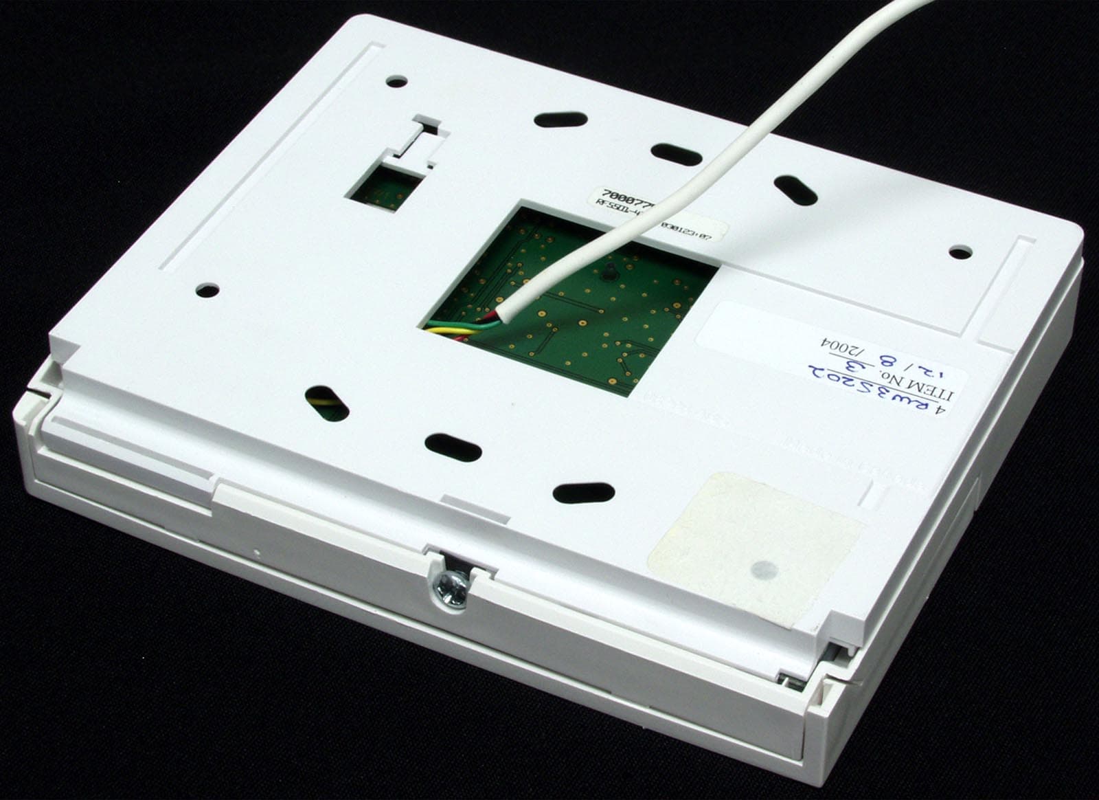
Click to zoom
Application Details
- Equipment Class
- CYY - Communications Receiver used w/Pt 15 Transmitter
- Date of Grant
- Jan 06, 2005
- Application Purpose
- Original Equipment
- Date of Application
- Jan 06, 2005
- Equipment Note
- RF5501-433NA UHF Receiver
- Frequency Range
- 433.92000000 - 433.92000000
- Country
- Canada
Documents & Files
Document Text
Text extracted from the exhibit documents filed with the FCC. Open a document above to read the original.
Users Manual
Installation Manual RF5501-433 version 5.O WARNING: Please refer to the System Installation Manual for information on limitations regarding product use and function and information on the limitations as to liability of the manufacturer. DLS2002 and higher WARNING Please Read Carefully Note to Installers This warning contains vital information. As the only individual in contact with system users, it is your responsibility to bring each item in this warning to the attention of the users of this system. System Failures This system has been carefully designed to be as effective as pos- sible. There are circumstances, however, involving fire, burglary, or other types of emergencies where it may not provide protection. Any alarm system of any type may be compromised deliberately or may fail to operate as expected for a variety of reasons. Some but not all of these reasons may be: ■■ ■■ ■ Inadequate Installation A security system must be installed properly in order to provide adequate protection. Every installation should be evaluated by a se- curity professional to ensure that all access points and areas are cov- ered. Locks and latches on windows and doors must be secure and operate as intended. Windows, doors, walls, ceilings and other build- ing materials must be of sufficient strength and construction to pro- vide the level of protection expected. A reevaluation must be done during and after any construction activity. An evaluation by the fire and/or police department is highly recommended if this service is available. ■■ ■■ ■ Criminal Knowledge This system contains security features which were known to be ef- fective at the time of manufacture. It is possible for persons with criminal intent to develop techniques which reduce the effectiveness of these features. It is important that a security system be reviewed periodically to ensure that its features remain effective and that it be updated or replaced if it is found that it does not provide the protec- tion expected. ■■ ■■ ■ Access by Intruders Intruders may enter through an unprotected access point, circum- vent a sensing device, evade detection by moving through an area of insufficient coverage, disconnect a warning device, or interfere with or prevent the proper operation of the system. ■■ ■■ ■ Power Failure Control units, intrusion detectors, smoke detectors and many other security devices require an adequate power supply for proper opera- tion. If a device operates from batteries, it is possible for the batter- ies to fail. Even if the batteries have not failed, they must be charged, in good condition and installed correctly. If a device operates only by AC power, any interruption, however brief, will render that de- vice inoperative while it does not have power. Power interruptions of any length are often accompanied by voltage fluctuations which may damage electronic equipment such as a security system. After a power interruption has occurred, immediately conduct a complete system test to ensure that the system operates as intended. ■■ ■■ ■ Failure of Replaceable Batteries This system’s wireless transmitters have been designed to provide several years of battery life under normal conditions. The expected battery life is a function of the device environment, usage and type. Ambient conditions such as high humidity, high or low tempera- tures, or large temperature fluctuations may reduce the expected battery life. While each transmitting device has a low battery moni- tor which identifies when the batteries need to be replaced, this moni- tor may fail to operate as expected. Regular testing and maintenance will keep the system in good operating condition. ■■ ■■ ■ Compromise of Radio Frequency (Wireless) Devices Signals may not reach the receiver under all circumstances which could include metal objects placed on or near the radio path or delib- erate jamming or other inadvertent radio signal interference. ■■ ■■ ■ System Users A user may not be able to operate a panic or emergency switch pos- sibly due to permanent or temporary physical disability, inability to reach the device in time, or unfamiliarity with the correct operation. It is important that all system users be trained in the correct opera- tion of the alarm system and that they know how to respond when the system indicates an alarm. ■■ ■■ ■ Smoke Detectors Smoke detectors that are a part of this system may not properly alert occupants of a fire for a number of reasons, some of which follow. The smoke detectors may have been improperly installed or posi- tioned. Smoke may not be able to reach the smoke detectors, such as when the fire is in a chimney, walls or roofs, or on the other side of closed doors. Smoke detectors may not detect smoke from fires on another level of the residence or building. Every fire is different in the amount of smoke produced and the rate of burning. Smoke detectors cannot sense all types of fires equally well. Smoke detectors may not provide timely warning of fires caused by carelessness or safety hazards such as smoking in bed, violent explosions, escaping gas, improper storage of flammable materials, overloaded electrical circuits, children playing with matches or arson. Even if the smoke detector operates as intended, there may be cir- cumstances when there is insufficient warning to allow all occu- pants to escape in time to avoid injury or death. ■■ ■■ ■ Motion Detectors Motion detectors can only detect motion within the designated ar- eas as shown in their respective installation instructions. They can- not discriminate between intruders and intended occupants. Motion detectors do not provide volumetric area protection. They have mul- tiple beams of detection and motion can only be detected in unob- structed areas covered by these beams. They cannot detect motion which occurs behind walls, ceilings, floor, closed doors, glass parti- tions, glass doors or windows. Any type of tampering whether in- tentional or unintentional such as masking,…
Text truncated - open the document above for the full version.
Attestation Statements
Nemko Canada Inc 303 River Road Ottawa, Ontario, Canada K1V 1H2 Attn: Director of Certification Authority to Act as Agent On our behalf, I appoint Nemko Canada Inc., 303 River Road, Ottawa, ON, Canada K1V 1H2, to act as our agent in the preparation of this application for equipment certification. I certify that submitted documents properly describe the device or system for which equipment certification is sought. I also certify that each unit manufactured, imported or marketed, as defined in the Federal Communications Commission’s regulations will have affixed to it a label identical to that submitted for approval with this application. For instances where our authorized agent signs the application for certification on our behalf, I acknowledge that all responsibility for complying with the terms and conditions for certification, as specified by Nemko Canada Inc, still resides with Digital Security Controls, 3301 Langstaff Rd, Concord, ON, Canada L4K 4L2. Dated this 10th Day of December 20 04 Agency agreement expiration date: December 10th, 2005 By: Dan Nita Signature Printed Title: Approvals Manager On behalf of : DSC Telephone: 905-760-3000
Cover Letter(s)
Equipment Authorization Division Federal Communications Commission 7435 Oakland Mills Road Columbia, MD 21046 FCC ID: F5305RF5501NA Product Name: RF5501-433NA Request for Confidentiality Pursuant to Sections 0.457 and 0.459 of the commissions rules, we hereby request that the following documents be held confidential: • Schematics • Block diagram and operational description • Parts List These materials contain trade secrets and proprietary information and are not customarily released to the public. The public disclosure of this information might be harmful to the company and provide unjustified benefits to our competitors. Dated this 10th Day of December 20 04 By: Dan Nita Signature Printed Title: Approvals Manager On behalf of : DSC Telephone: 905-760-3000
ID Label/Location Info
Digital Security Controls ISO9001 Registered 3301 Langstaff Road, Concord Ontario, Canada L4K 4L2 Phone: 905-760-3000 Toll Free: 1-888-888-7838 Fax: 905-760-3030 DASHED LINE INDICATES CUT EDGE OF LABEL LABEL TO BE PRINTED ON SELF-ADHESIVE MATERIAL LABEL SHOWN 200% ACTUAL SIZE 50 mm 26 mm FCC/IC Labeling for RF5501-433NA File: [180xxxxx_REV_001_RF5501-433NA_FCC-IC_LB-FORMAT_MYLAR.cdr] Dec 6/04 Bottom of the unit showing placement of label (Actual size) ® FCCID:F5305RF5501NA Model: RF5501-433NA DigitalSecurityControls This device complies with Part 15 of the FCC Rules. Operation is subject to the following two conditions: (1) This device may not cause harmful interference, and (2) this device must accept any interference re- ceived, including interference that may cause unde- sired operation. 180xxxxxRev001 IC:160A-RF5501NA MADEINCANADA This Class B digital apparatus meets all require- ments of the ICES-003. Cet appareil numérique de la classe B respecte toutes les exigences du ICES- 003. FCCID:F5305RF5501NA 180xxxxxRev001 Model: RF5501-433NA DigitalSecurityControls IC:160A-RF5501NA MADEINCANADA This device complies with Part 15 of the FCC Rules. Operation is subject to the following two conditions: (1) This device may not cause harmful interference, and (2) this device must accept any interference re- ceived, including interference that may cause unde- sired operation. This Class B digital apparatus meets all require- ments of the ICES-003. Cet appareil numérique de la classe B respecte toutes les exigences du ICES- 003.
Test Report
Master: FCC Part15 SubpartB.doc - Date: April 5, 2004 Test Report: 4R35202.1 Applicant: Digital Security Controls Ltd. 3301 Langstaff Road Concord, ON Canada L4K 4L2 Equipment Under Test: Keypad with RF Receiver for Alarm System Model Number: RF5501-433NA In Accordance With: FCC Part 15, Subpart B Tested By: Nemko Canada Inc. 303 River Road, R.R. 5 Ottawa, Ontario K1V 1H2 Authorized By: Glen Westwell, Wireless Specialist Date: 23 December 2004 Total Number of Pages: 16 Reference Standard: FCC Part 15, Subpart B Test Report No: 4R35202.1 Nemko Canada Inc., Ottawa, Ontario Canada Equipment (EUT): Keypad with RF Receiver for Alarm System Page 2 of 16 Table of Contents Measurement Uncertainty ........................................................................................................................................... 3 Lab Environmental Conditions ................................................................................................................................... 3 Declaration.................................................................................................................................................................. 4 Summary of Test Results ............................................................................................................................................ 5 Engineering Considerations ........................................................................................................................................ 7 General Information Regarding the Equipment Under Test (EUT) ........................................................................... 8 Equipment Configuration ........................................................................................................................................... 9 Radiated Disturbance ................................................................................................................................................ 10 Conducted Disturbance at Mains Port ...................................................................................................................... 12 Nemko Canada Inc. authorizes the applicant to reproduce this report provided it is reproduced in its entirety and for use by the company’s employees only. Any use which a third party makes of this report, or any reliance on or decisions to be made based on it, are the responsibility of such third parties. Nemko Canada Inc. accepts no responsibility for damages, if any suffered by any third party as a result of decisions made or actions based on this report. This report shall not be reproduced except in full without the written approval of the testing laboratory. Reference Standard: FCC Part 15, Subpart B Test Report No: 4R35202.1 Nemko Canada Inc., Ottawa, Ontario Canada Equipment (EUT): Keypad with RF Receiver for Alarm System Page 3 of 16 Measurement Uncertainty Accuracy of Measurement Measurement uncertainty was calculated using the methods described in CISPR 16-4 Specification for radio disturbance and immunity measuring apparatus and methods – Part 4: Uncertainty in EMC measurements and Nemko Canada Inc. procedure EMC/MUC/001 Uncertainty in EMC Measurements. Test Specific Measurement Uncertainty Measurement Test Specification Ulab 9kHz – 150kHz 4.0dB Conducted disturbance 150kHz – 30MHz 3.6dB 30MHz – 200MHz Horizontal polarization 4.7dB 200MHz – 1000MHz Horizontal polarization 4.7dB 30MHz – 200MHz Vertical polarization 4.9dB Radiated disturbance 200MHz – 1000MHz Vertical polarization 4.9dB Lab Environmental Conditions Lab Conditions Ambient Temperature: 15°C to 35°C, Relative Humidity: 30% to 60%, Atmospheric Pressure: 86kPa (860mbar) to 106kPa (1 060mbar) Reference Standard: FCC Part 15, Subpart B Test Report No: 4R35202.1 Nemko Canada Inc., Ottawa, Ontario Canada Equipment (EUT): Keypad with RF Receiver for Alarm System Page 4 of 16 Declaration Product Name: Keypad with RF Receiver for Alarm System Model No: RF5501-433NA Trademark: Serial No: None Name of Applicant: Digital Security Controls Ltd. Name of Manufacturer: Digital Security Controls Ltd. TEST RESULT Nemko Canada Inc., Ottawa, Ontario Canada PASS FAIL In the configuration tested, the EUT complied with the requirements of: FCC 47 CFR Part 15, Subpart B: Paragraph No. 15.107, Paragraph No. 15.109, and Paragraph No. 15.111 X Note: See Summary of Test Results and Engineering Considerations for full details. Tested by: 23 December 2004 Signature Date David Duchesne, EMC Specialist Reviewed by: 23 December 2004 Signature Date Glen Westwell, EMC Specialist Nemko Canada Inc., a testing laboratory, is accredited by the Standards Council of Canada. The tests included in this report are within the scope of this accreditation. Reference Standard: FCC Part 15, Subpart B Test Report No: 4R35202.1 Nemko Canada Inc., Ottawa, Ontario Canada Equipment (EUT): Keypad with RF Receiver for Alarm System Page 5 of 16 Summary of Test Results General These tests were conducted on a sample of the equipment for the purpose of demonstrating compliance with FCC Part 15, Subpart B, 15109. Radiated Emissions were measured on an open area test site. A description of the test facility is on file with the FCC. These tests were conducted using measurement procedures of ANSI C63.4-2001. The equipment was tested for conducted emissions from 0.15MHz to 30MHz using a 50 microhenry line impedance stabilization network (L.I.S.N.) as described in ANSI C63.4-2001. Peripheral equipment was also operated through a 50 microhenry L.I.S.N. Limits For Conducted Disturbance At The Mains Ports: Paragraph No. 15.107 for Class A Limits dB(μV) Frequency Range MHz Quasi-Peak Average Result (Pass/Fail) 0.15 to 0.50 79 66 0.50 to 30 73 60 N/A Limits For Conducted Disturbance At The Mains Ports: Paragraph No. 15.107 for Class B Limits dB(μV) Frequency Range MHz Quasi-Peak Average Result (Pass/Fail) 0.15 to 0.50 66 to 56 56 to 46 0.5 to 5 56 46 5 to 30 60 50 Pass Notes 1. The l…
Text truncated - open the document above for the full version.
Test Setup Photos
Reference Standard: FCC Part 15, Subpart B Test Report No: 4R35202.1 Nemko Canada Inc., Ottawa, Ontario Canada Equipment (EUT): Keypad with RF Receiver for Alarm System Page 11 of 16 Radiated Disturbance, continued Radiated Disturbance Setup Photos
Test Setup Photos
Reference Standard: FCC Part 15, Subpart B Test Report No: 4R35202.1 Nemko Canada Inc., Ottawa, Ontario Canada Equipment (EUT): Keypad with RF Receiver for Alarm System Page 14 of 16 Conducted Disturbance at Mains, continued Conducted Disturbance at Mains Setup Photos
Contact Information
Applicant
Dan Nita(Approvals Manager)
Technical Contact
Test Firm
Nemko Canada Inc. (Ottawa)Charles Neal
Technical Specifications
| # | Rule Parts | Frequency Range | Power Output |
|---|---|---|---|
| 1 | 15B | 433.92 MHz - 433.92 MHz | - |
Other Applications from Tyco Safety Products Canada Ltd.

F53252RFLOCK
Jun 05, 2026IQ Lock-PGP, IQ Lock Touch-PGP
Equipment Class
DTS - Digital Transmission System
F5325PGPDC9
Apr 27, 2026PowerG wireless transceiver module
Equipment Class
DSS - Part 15 Spread Spectrum Transmitter
F5325LC203424
Dec 17, 2025Dual Technology Motion Sensor
Equipment Class
FDS - Part 15 Field Disturbance SensorF5324PGPIO9
Dec 04, 2024Wireless Input / Output (I/O) w/wo contact
Equipment Class
DSS - Part 15 Spread Spectrum Transmitter
F5323PGP9934P
Jan 16, 2024Wireless Motion detector with integrated camera
Equipment Class
DSS - Part 15 Spread Spectrum Transmitter