F5306F23XField Disturbance Sensor
Tyco Safety Products Canada Ltd.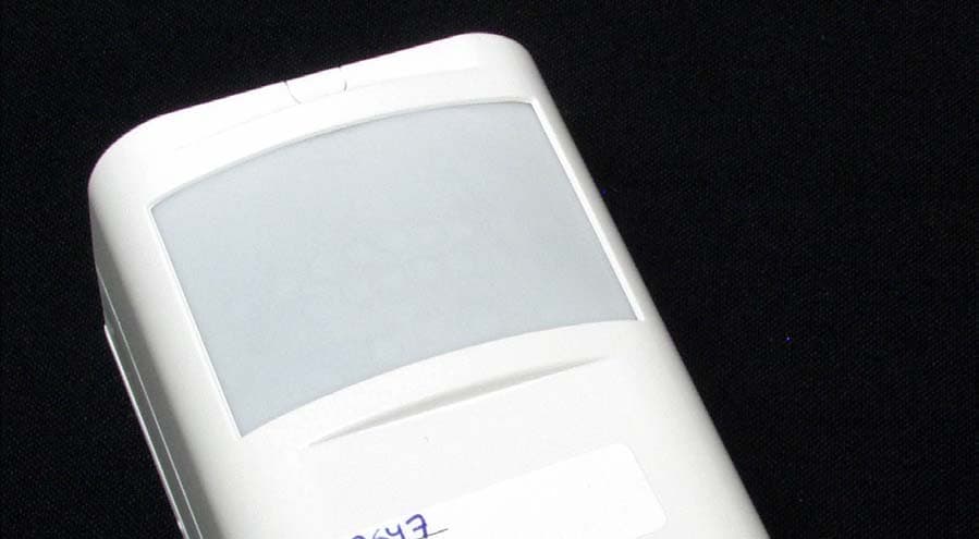
Click to zoom
Application Details
- Equipment Class
- FDS - Part 15 Field Disturbance Sensor
- Date of Grant
- Feb 01, 2006
- Application Purpose
- Original Equipment
- Date of Application
- Feb 01, 2006
- Equipment Note
- Field Disturbance Sensor
- Frequency Range
- 10525.00000000 - 10525.00000000
- Country
- Canada
Documents & Files
Document Text
Text extracted from the exhibit documents filed with the FCC. Open a document above to read the original.
Users Manual
F2-300 Series DUAL TECHNOLOGY DETECTORS DETECTORES DE TECNOLOGÍA DOBLE DETECTEURS DOUBLE TECHNOLOGIE RILEVATORI DOPPIA TECNOLOGIA CZUJKI DUALNE ENGLISH !DSC re serves the right to change the tech ni cal spec i fi ca tions of this prod uct with out prior no tice. !This equip ment shall be in stalled in non-haz ard ous lo ca tions by ser vice per sons only. !These in struc tions shall be used in con junc tion with the Alarm con trol ler's man ual to which the sen sors are in tended to be con nected. !The Power Sup ply that pro vides power to this unit shall be a Lim ited Power PS as it is de fined within the EN60950-1: 2001+A11:2004. DESCRIPTIONThe F2-300 Se ries de tec tors pro vide a com bi na - tion of mi cro wave and in fra red de tect ing in side a sin gle cas ing. Es pe cially de signed for dif fi cult ap pli ca tions, the F2-300 Se ries pro vides im pres sive de tec tion per for mance with ex cep tion ally low false alarm rate. Con forms with CEI 79-2 2nd Ed. stan dards, Per - for mance Clas si fi ca tion Grade I. F2-300 Se ries mod els: ÿF2-301 / F2-302 – Mi cro pro ces sor con trolled with AND or AND/OR Alarm anal y sis with Alarm Mem ory and Dis able Mi - cro wave op tions ÿF2-303 / F2-304 – AND Alarm anal y sis with Alarm Mem ory and Dis able Mi cro wave op tions ÿF2-305 / F2-306 – AND Alarm anal y sis with built-in mi cro phone The in for ma tion in this leaf let ap plies to all the F2-300 Se ries mod - els, un less oth er wise stated. COVERFig. 1 shows the cover pro vided by the in fra red sen sor and the mi cro wave (in di cated by dot ted line) when the ver ti cal an - gle of the De tec tor is -5°. INSTALLATION (Fig. 2)The De tec tor can be: ÿbackplate mounted at a ver ti cal an gle of -5°/-10°; ÿcor ner mounted at a vertcal an gle of -5°/-10°; ÿside mounted at a hor i zon tal an gle of ±20° and a ver ti cal an gle of -5°/-10°; 1.Re move the screw cap 1 and screw 2, then de tach the cover 3. 2.Choose the mount ing lo ca tion, tak ing into con sid er ation the most likely path an in truder would take. The rec om mended mount ing height is 2.1 meters. 3.Se lect the ap pro pri ate bracket then re move the knock outs, as per Ta ble 1 and Fig ure 3. 4.Pass the con nec tion wires (not the in su la tion) through the wire en try (see Tab. 1 and Fig. 3). +If you are backplate-mount ing the de tec tor with ex ter nally routed wir ing, use knock outs 6. 5.Po si tion the bracket as re quired (see in di ca tions on bracket) then, us ing the an chor screws, se cure it in place (see Tab. 1 and Fig. 3). 6.Pass the con nec tion wires through ap er tures 4, then at tach the backplate 5 to the bracket (7 or 8). 7.Carry out the con nec tions and set the op er at ing mode (re fer to the in struc tions in the re spec tive para graphs). 8.Re at tach the cover 3 then re place the screw 2 and screw cap 1. 9.Carry out a Walk Test. CONNECTIONSUse shielded ca ble for the con nec tion. Con nect one end of the shield to the Con trol panel neg a tive and leave the other end (de tec tor end) dis con nected. If the de tec tor is a con sid er able dis - tance from the Con trol panel, check for volt age drop (re quired volt age range: 9 V to 15 V). TER.DESCRIPTION AS Tam per con tact nor mally closed: con nect to the con trol panel tam per line NC Alarm re lay con tact nor mally closed: con nect to the con trol panel Alarm line MWDis ables Mi cro wave (F2-301 / F2-302 / F2-303 / F2304) MEn ables Mem ory (F2-301 / F2-302 / F2-303 / F2-304) + / – De tec tor power sup ply: 12 V_ GNDMi cro phone ter mi nal: neg a tive (F2-305 / F2-306) MICMi cro phone ter mi nal: pos i tive (F2-305 / F2-306) +The de tec tor will sta bi lize ap prox i mately 60 sec onds af ter power up (for mod els: F2-303, F2-304, F2-305, F2-306). The sta bi li za tion phase will be in di cated by glow ing on the red LED. 90° a) b) 0 5 5 510 m 2.1 0 0 m m -5° Fig. 1Cover: a) top view; b) side view Tapa: a) vis ta des de arri ba; b) vis ta la te ral Cou vercle: a) vue de des sus; b) vue la té rale Co per tu ra: a) vi sta in pian ta; b) vi sta la te ra le Po krywa: a) wi dok z góry; b) wi dok z boku ° - 1 0 ° - 5 ° - 1 0 ° - 5 W T N C A S A B 1266443578 Fig. 2De tec tor com po nents Com po nen tes del de tec tor Com po sants du dé tec teur Par ti del Rilevatore Czê œci sk³ad owe czuj ki a) A J H D FG B M N O P K C L I E b) Fig. 3Brack ets: a) Cor ner/Side-mount; b) Backplate-mount Escua dras: a) Mon ta je en es qui na/la te ral; b) Mon ta je en pa red Sup ports: a) Mon ta ge en coin/la té ral; b) Mon ta ge par la pla que arriè re Staffe: a) mon tag gio ad angolo; b) mon tag gio in piano Wspor niki: a) monta¿ naro¿ ny; b) monta¿ œcien ny ITALIANO !Le spe ci fi che del pro dot to pos so no su bi re va ria zio ni sen za pre av vi so. !Qu e sto ap pa rec chio deve es se re in stal la to in una zona non clas si fi ca ta da per so na - le tec ni co spe cia liz za to. !Con sul ta re que ste istru zio ni uni ta men te al re la ti vo ma nua le del con trol lo re del l'al - lar me. !L'a li men ta to re adat to a que sto ap pa rec chio sarà del tipo a po ten za li mi ta ta come de fi ni to dal lo stan dard EN60950-1: 2001+A11:2004. DESCRIZIONEI ri le va to ri del la Se rie F2-300 com bi na no in un uni - co di spo si ti vo un sen so re a mi cro on da ed un sen so re ad in fra ros so. Appo si ta men te stu dia ti e re a liz za ti per il fun zio na men to in am bien ti mol to dif fi ci li, ga ran ti sco no un ec cel len te gra do di im mu ni tà a fe no - me ni che in al tri tipi di ri le va to ri pos so no ca u sa re fal si al lar mi. Con - for mi alle nor me CEI 79-2 2a Ed., Li vel lo di Pre sta zio ne I. I ri le va to ri del la se rie F2-300 sono di spo ni bi li nel le se guen ti ver sio ni: ÿF2-301 / F2-302 – a mi cro pro ces so re, ana li si AND ed AND/OR, me mo ria, mi cro on da esclu di bi le; ÿF2-303 / F2-304 – ana li si AND, me mo ria, mi cro on da esclu di bi le; ÿF2-305 / F2-306 – ana li si AND, mi cro fo no. Le in for ma zio ni con te nu te in que st…
Text truncated - open the document above for the full version.
Cover Letter(s)
December 19, 2005 Nemko Canada Inc 303 River Road Ottawa, Ontario, Canada K1V 1H2 Attn: Director of Certification Authority to Act as Agent On our behalf, I appoint Nemko Canada Inc., 303 River Road, Ottawa, Ontario, Canada K1V 1H2 to act as our agent in the preparation of this application for equipment certification. I certify that submitted documents properly describe the device or system for which equipment certification is sought. I also certify that each unit manufactured, imported or marketed, as defined in the Federal Communications Commission’s regulations will have affixed to it a label identical to that submitted for approval with this application. For instances where our authorized agent signs the application for certification on our behalf, I acknowledge that all responsibility for complying with the terms and conditions for certification, as specified by Nemko Canada Inc, still resides with Digital Security Controls, 3301 Langstaff Road, Concord, Ontario Canada L4K 4L2. Dated this 19th Day of December 20 05 Agency agreement expiration date: December 19, 2006 By: Dan Nita Signature Printed Title: Approvals Manager On behalf of : Digital Security Controls Telephone: 905-760-3000, Ext. 2706
Cover Letter(s)
December 19, 2005 Equipment Authorisation Division Federal Communications Commission 7435 Oakland Mills Road Columbia, MD 21046 FCC ID: F5306F23X Product Name: F2-301, F2-302, F2-303, F2-304, F2-305, F2-306 Request for Confidentiality Pursuant to Sections 0.457 and 0.459 of the commissions rules, we hereby request that the following documents be held confidential: (List here the documents for which you are seeking confidentiality – for example ...) • Schematics • Component layout drawings • Parts lists • Block diagram • Operational description These materials contain trade secrets and proprietary information and are not customarily released to the public. The public disclosure of this information might be harmful to the company and provide unjustified benefits to our competitors. Dated this 19th Day of December 20 05 By: Dan Nita Signature Printed Title: Approval Manager On behalf of : Digital Security Controls Telephone: 905-760-3000, Ext. 2706
Cover Letter(s)
1 December 19, 2005 To Whom It May Concern: The DSC F2-300 series of Motion Detectors are built using the same enclosure, lens, PIR sensor and Microwave sensor and have similar functionality. The only differences are related to the features that each model can offer for a certain type of installation as follows: F2-301 – PIR and/or MW functionality, PIR detector with selectable pulses between 2-6, Alarm memory function, uses10.525GHz frequency for microwave (MW) sensor. F2-302 – same as F2-301 but uses 10.515GHz frequency for microwave (MW) sensor. F2-303 – PIR and MW functionality only, PIR detector with selectable pulses between 1- 2, Alarm memory function, uses 10.525GHz frequency for microwave (MW) sensor. F2-304 – same as F2-303 PIR and MW detector, but uses 10.515GHz frequency for microwave (MW) sensor. F2-305 – PIR and MW functionality only, provided with microphone for remote listen in capability, uses 10.525GHz frequency for microwave (MW) sensor. F2-306 – same as F2-305 but uses 10.515GHz frequency for microwave (MW) sensor. Respectfully yours, Dan Nita Approvals Manager
ID Label/Location Info
December 19, 2005 Label Format and Location Diagram F2-300 Series of Motion Detectors F2-301, F2-302, F2-303, F2-304, F2-305, F2-306 The label has the dimensions: 0.5 by 2.0 in. and it will be applied on the rear cover. Label placement diagram: Rear Cover of the F2-300 Series of Motion Detectors FCC ID: F5306F23X Digital Security Controls Model: F2-3011 F2-3021 F2-3031 F2-3041 F2-3051 F2-3061 This device complies with Part 15 of the FCC Rules. Operation is subject to the following two conditions: (1) This device may not cause harmful interference, and (2) This device must accept any interference received, including interference that may cause undesired operation This Class B digital apparatus meets all requirements of the ICES-003. Cet appareil numérique de la classe B respecte toutes les exigence du ICES-003. IC: 160A-06F23X MADE IN CANADA 180xxxxx FCC/IC LABEL
Test Report
FCC Part 15 Subpart C, 15.245 : December 2005 Test Report: 5W57547 Issue 2 Applicant: Digital Security Controls Ltd 3301 Langstaff Road, Vaughan, Ontario L4K 4L2 Apparatus: F2-300 Series Motion Detectors FCC ID: F5306F23X In Accordance With: FCC Part 15 Subpart C, 15.245 Operation within the bands 902-928 MHz, 2435- 2465 MHz, 5785-5815 MHz, 10500-10550 MHz and 24075-24175 MHz Tested By: Nemko Canada Inc. 303 River Road Ottawa, Ontario K1V 1H2 Authorized By: Sim Jagpal, Resource Manager Date: January 31, 2006 Total Number of Pages: 22 Nemko Canada Inc. REPORT SUMMARY Report Number: 5W57547 Issue 2 FCC ID: F5306F23X Specification: FCC Part 15 Subpart C, 15.245 Page 2 of 22 Report Summary These tests were conducted on a sample of the equipment for the purpose of demonstrating compliance with Part 15, Subpart C. Radiated tests were conducted in accordance with ANSI C63.4-2003. Radiated emissions are made on an open area test site. A description of the test facility is on file with the FCC. The assessment summary is as follows: Apparatus Assessed: F2-300 Series Motion Detectors Specification: FCC Part 15 Subpart C, 15.245 Compliance Status: Complies Exclusions: None Non-compliances: None Report Release History: Issue 2 – Addition of 20dB bandwidth test results and AC Power line conducted results Author: Jason Nixon, Telecom Specialist Note that the results contained in this report relate only to the items tested and were obtained in the period between the date of initial receipt of samples and the date of issue of the report. This test report has been completed in accordance with the requirements of ISO/IEC 17025. Nemko Canada Inc. authorizes the applicant to reproduce this report provided it is reproduced in its entirety and for use by the company’s employees only. Any use which a third party makes of this report, or any reliance on or decisions to be made based on it, are the responsibility of such third parties. Nemko Canada Inc. accepts no responsibility for damages, if any, suffered by any third party as a result of decisions made or actions based on this report. Nemko Canada Inc. REPORT SUMMARY Report Number: 5W57547 Issue 2 FCC ID: F5306F23X Specification: FCC Part 15 Subpart C, 15.245 Page 3 of 22 TABLE OF CONTENTS Report Summary......................................................................................................................................... 2 Section 1 : Equipment Under Test............................................................................................................. 4 1.1 Product Identification .................................................................................................................................4 1.2 Samples Submitted for Assessment............................................................................................................4 1.3 Theory of Operation ...................................................................................................................................4 1.4 Technical Specifications of the EUT ..........................................................................................................5 1.5 Block Diagram of the EUT.........................................................................................................................5 Section 2 : Test Conditions......................................................................................................................... 6 2.1 Specifications .............................................................................................................................................6 2.2 Deviations From Laboratory Test Procedures ............................................................................................6 2.3 Test Environment .......................................................................................................................................6 2.4 Test Equipment...........................................................................................................................................6 Section 3 : Observations ............................................................................................................................. 7 3.1 Modifications Performed During Assessment ............................................................................................7 3.2 Record Of Technical Judgements ...............................................................................................................7 3.3 EUT Parameters Affecting Compliance .....................................................................................................7 3.4 Test Deleted................................................................................................................................................7 3.5 Additional Observations .............................................................................................................................7 Section 4 : Results Summary ..................................................................................................................... 8 4.1 FCC Part 15 Subpart C : Test Results ........................................................................................................9 Appendix A : Test Results ........................................................................................................................ 10 Clause 15.245(b) Radiated emissions not in Restricted Bands............................................................................17 Appendix B : Setup Photographs ............................................................................................................ 21 Appendix C : Block Diagram of Test Setups .......................................................................................... 22 Nemko Canada Inc. SECTION 1 : EQUIPMENT UNDER TEST Report Number: 5W57547 Issue 2 FCC ID: F5306F23X Specification: FCC Part 15 Subpart C, 15.245 Page …
Text truncated - open the document above for the full version.
Test Setup Photos
Radiated Emissions Setup: Conducted Emissions Setup:
Contact Information
Applicant
Dan Nita(Approvals Manager)
Technical Contact
Digital Security Controls, a Division of Tyco SafeDan Nita
[email protected]905 760 3000
3301 Langstaff Road · Concord · Canada
Non-Technical Contact
Digital Security Controls, a Division of Tyco SafeDan Nita
[email protected]905 760 3000
Test Firm
Nemko Canada Inc. (Ottawa)Charles Neal
Technical Specifications
| # | Rule Parts | Frequency Range | Power Output |
|---|---|---|---|
| 2 | 15.245 | 10.53 GHz - 10.53 GHz | - |
Other Applications from Tyco Safety Products Canada Ltd.

F53252RFLOCK
Jun 05, 2026IQ Lock-PGP, IQ Lock Touch-PGP
Equipment Class
DTS - Digital Transmission System
F5325PGPDC9
Apr 27, 2026PowerG wireless transceiver module
Equipment Class
DSS - Part 15 Spread Spectrum Transmitter
F5325LC203424
Dec 17, 2025Dual Technology Motion Sensor
Equipment Class
FDS - Part 15 Field Disturbance SensorF5324PGPIO9
Dec 04, 2024Wireless Input / Output (I/O) w/wo contact
Equipment Class
DSS - Part 15 Spread Spectrum Transmitter
F5323PGP9934P
Jan 16, 2024Wireless Motion detector with integrated camera
Equipment Class
DSS - Part 15 Spread Spectrum Transmitter