F5306LC3105Motion Detector
Tyco Safety Products Canada Ltd.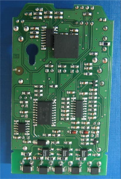
Click to zoom
Application Details
- Equipment Class
- FDS - Part 15 Field Disturbance Sensor
- Date of Grant
- Jan 10, 2007
- Application Purpose
- Original Equipment
- Date of Application
- Jan 09, 2007
- Equipment Note
- Motion Detector
- Frequency Range
- 10525.00000000 - 10525.00000000
- Country
- Canada
Documents & Files
Document Text
Text extracted from the exhibit documents filed with the FCC. Open a document above to read the original.
Users Manual
POLSKI Czujka LC-103PIMSK zapewnia analizę warunków otoczenia w pełnym spektrum częstotliwości prędkości ruchu pozwalając na wykrywanie intruzów przy równoczesnej eliminacji czynników środowiskowych i wynikających z nich fałszywych alarmów. Analiza widmowa realizowana przez elektronikę czujki opartą na układach VLSI gwarantuje wysoką niezawodność i brak zakłóceń w działaniu. Unikalna funkcja - antymaskingu - gwarantuje ochronę czujki przed niepożądanym zbliżaniem się do niej i próbami jej maskowania w odległości 0,8 m i bliżej. Ponieważ czujka LC-103PIMSK / LC-123-PIMSK wykorzystuje łączoną technologię (pasywna podczerwień i detekcja mikrofalowa) uruchomienie przekaźnika sygnału alarmowego następuje dopiero wtedy, gdy obydwa czujniki (pasywnej podczerwieni i detekcji mikrofalowej) w tym samym czasie zostan ą naruszone. Efektywny zasięg detekcji jest tym zasięgiem, w którym pokrywają się charakterystyki detekcji czujników pasywne j podczerwieni i detekcji mikrofalowej. Regulacja dokonywana przy użyciu potencjometru GAIN zmienia intensywność sygnału mikrofalowego, dlatego też efektywna charakterystyka detekcji może być skalowana. Przed przystąpieniem do instalacji czujki należy dokładnie zapoznać się z poniższą instrukcją. WYBÓR MIEJSCA INSTALACJI Czujkę należy zainstalować w taki sposób, aby jej zasięg działa nia objął chronione pomieszczenie (Rys. 3). Wysokiej jakości czteroelementowy czujnik QUAD jest bardziej wrażliwy na ruch przecinający wiązkę, niż na ruch skierowany w stronę czujnika. Aby uniknąć fałszywych alarmów, podczas montażu należy przestrzegać poniższe zasady: *Nie wolno kierować czujki bezpośrednio w stronę światła słonecznego. *Nie wolno umieszczać czujki w pobliżu przedmiotów, lub obszarów, które gwałtownie mogą zmienić swą temperaturę. *Nie wolno kierować czujki bezpośrednio w stronę urządzeń wytwarzających strumienie powietrza. Czujka przeznaczona jest do montażu w środowisku o maksymalnie 2 stopniu zanieczyszczenia i możliwości występowania przepięć kategorii II. Czujka przeznaczona jest wyłącznie do montażu wewnętrznego. Montaż czujki powinien wykonywać wyłącznie wykwalifikowany instalator systemów alarmowych. UWAGA: Czujka LC-103PIMSK odcina sygnał alarmu antymaskingu dopiero po otrzymaniu sygnału od czujnika pasywnej podczerwieni PIR, lecz nie wcześniej niż 30 sek. po aktywacji alarmu antymaskingu. MONTAŻ URZĄDZENIA 1. W celu zdjęcia osłony czołowej należy wykręcić śrubę mocującą (Rys. 2-11) a następnie delikatnie unieść osłonę(Rys.2-5) 2. W celu wyjęcia płytki drukowanej należy wykręcić śrubę mocującą umieszczoną na płytce (Rys. 2-9). 3. Wykonać otwory na tylnej części obudowy urządzenia w miejscu przewidzianym na śruby mocujące (Rys. 1-2 lub 1-3, do montażu na płaskiej powierchni lub do montażu narożnego). Przymocować urządzenie za pomocą 4 śrub. 4. Wykonać otwory na tylnej części obudowy w miejscu przewidzianym na przewody (Rys. 1-1 i 1-4). 5. Zamontować tylną część obudowy urządzenia na ścianie lub w narożniku. 6. Jeżeli używany jest opcjonalny uchwyt należy wykonać otwór na śrubę uchwytu (Rys. 1-6) i zamontować adapter do montażu na ścianie (Rys. 2-1 i 3) lub adapter do montażu na suficie (Rys. 2-2 i 3). 7. Ponownie zamontować płytkę drukowaną dokręcając śrubę mocującą. 8. Podłączyć przewody zgodnie ze schematem (Rys.4). 9. Zamknąć obudowę dopasowując do siebie zaciski znajdujące się na osłonie, następnie dokręcić śrubę znajdującą się w dolnej części osłony. Jeżeli założony jest sabotaż tylny (Rys. 1-6) to nie ma możliwo ści instalacji urządzenia z opcjonalnym uchwytem Czujka musi zostać zamontowana na ścianie. OPIS ZACISKÓW (Rys. 4) Zaciski 1 i 2 (oznaczone "T1,T2"): zaciski sabotażowe normalnie zwarte, należy podłączyć je do linii dozorowej antysabotażowej w centrali alarmowej. Zaciski 3 i 4 (oznaczone "AM NC,C"): są to zaciski wyjściowe przekaźnika alarmowego antymaskingu. Zacisk 5 (oznaczony "NC"): zacisk przekaźnika alarmu, normalnie zwarty NC (występuje w modelach LC-103-PIMSK i LC-123-PIMSK) Zacisk 6 (oznaczony "C"): zacisk wspólny przekaźnika alarmu (występuje w modelach LC-103-PIMSK i LC-123-PIMSK) . Zacisk 7 (oznaczony "NO"): zacisk przekaźnika alarmu, normalnie otwarty NO (występuje tylko w modelu LC-123-PIMSK) Zaciski 8 i 9 (oznaczone "12V +/-"): zaciski służące do podłączenia zasilania czujki 12V=. USTAWIANIE CZUJKI WŁĄCZANIE/WYŁĄCZANIE DIODY LED Przełącznik 1(LED)zestawu przełączników DIP-4. Pozycja górna "ON" - włączenie diody LED - CZERWONA DIODA LED zaświeci się, gdy czujka będzie w stanie alarmu. Pozycja dolna "OFF" - wyłączenie diody LED - diody LED są wyłączone. ITALIANO Questo rivelatore controlla le condizioni ambientali analizzando lo spettro completo delle frequenze della velocità di moto, concentrando l'attenzione sugli intrusi e eliminando i fattori ambientali che potrebbero causare falsi allarmi. L'analisi dello spettro è implementata nell'elettronica VLSI de l rilevatore a garanzia di un funzionamento affidabile e senza inconvenienti. L'esclusiva funzione di antimascheramento protegge il rilevatore contro eventuali interferenze esterne e ogni tipo di mascheramento fino ad una distanza di 0,8 m. Poiché l’LC-103-PIMSK / LC-123-PIMSK usa una tecnologia combinata (PIR e microonda) l’attivazione del relè di allarme s i verifica solo quando entrambi i sensori rilevano contemporaneamente un movimento. L’area di copertura effettiva è data dall’intersezione delle coperture dei due sensori (PIR e microonda). Il potenziometro GAIN modifica l’intensità del segn ale MW in modo da poter modificare la copertura effettiva. Queste istruzioni devono essere usate unitamente a quelle relative alla centrale dell'impianto di allarme. INSTALLAZIONE TIPICA Scelta della posizione per il montaggio Selezionare la posizione più adatta a rilevare la presenza di u n intruso. (Si raccomanda l'installazione ad angolo). Vedere l'ar ea di copertura (Fig. 3). Il sensore a quattro elementi ad elevata sensibilità rileva i movimenti che incrociano i fasci; esso è leggerm…
Text truncated - open the document above for the full version.
Cover Letter(s)
December 10, 2006 American TCB 6731 Whittier Ave. American TCB 6731 Whittier Ave Suite C110 McLean, VA 22101 USA Subject: Request for confidentiality, FCC ID:F5306LC3105 Dear Gentlemen, In regards the exhibits submitted in support of the application for FCC ID:F5306LC3105, please classify the following as confidential under the provision of 47 CFR 0.459: • Schematic diagram, file “Schematic_diagram_17541” (2 pages) Schematics • Block diagram • Operational description The above material contains trade secrets or technical data which Digital Security Controls Ltd. deems to be proprietary. Therefore this information would customarily be guarded from competitors and cannot be accessible to the general public. Dan Nita, Approvals Manager Digital Security Controls Ltd.
Cover Letter(s)
American Telecommunications Certification Body Inc. 6731 Whittier Ave, McLean, VA 22101 December 30, 2006 RE: Digital Security Controls, a Division of Tyco Safety Products Canada, Ltd. FCC ID: F5306LC3105 After a review of the submitted information, I have a few comments on the above referenced Application. 1) It appears that the internal photographs may be missing one side of the TX board. Please review/provide. 2) The schematics appear to be missing for the TX portion of the Device. Please review. 3) Test Photos appear to show the 30 – 1000 MHz in a fully-anechoic chamber. However ANSI C63.4 and the FCC expect testing from 30 – 1000 MHz to be on a properly configured OAT’s site. Please explain/review/correct as necessary. 4) The device received power via 12 VDC. However this does not appear to be battey power only. Therefore it is assumed power may be obtained from an AC adapter, or from another device which is also attached to AC power. In these cases, powerline AC conducted emissions are therefore still required. Please review 15.207(c). Timothy R. Johnson Examining Engineer mailto: [email protected] The items indicated above must be submitted before processing can continue on the above referenced application. Failure to provide the requested information may result in application termination. Correspondence should be considered part of the permanent submission and may be viewed from the Internet after a Grant of Equipment Authorization is issued. Please do not respond to this correspondence using the email reply button. In order for your response to be processed expeditiously, you must submit your documents through the AmericanTCB.com website. Also, please note that partial responses increase processing time and should not be submitted. Any questions about the content of this correspondence should be directed to the sender.
Cover Letter(s)
HERM O N LA BO RA TO RIES January 10, 2007 American TCB 6731 Whittier Ave Suite C110 McLean, VA 22101 Attn: Mr. T. Johnson, Examining Engineer RE: your e-mail dated December 30, 2006; Digital Security Controls Ltd. FCC ID:F5306LC3105, ATCB004368 Dear Mr. Johnson, Please find below the answers to your questions. 1) The revised file “Internal_photos_17541_rev1” with additional Tx board photograph was uploaded on January 10, 2007. 2) File “Schematic_diagram_17541” includes the Tx-Rx module labeled the “DP1 NJR4178”. The data sheet for NJR4178 module manufactured by JRC was uploaded on January 10, 2007. 3) No emissions were found during testing in the fully-anechoic chamber in 30-1000 MHz range (please refer to plot 7.1.3 of the test report CRORAD_FCC.17541_rev1.1), that is why no need to investigate at OATS. 4) In normal use the device is powered from a control panel attached to AC mains. The device was tested according to FCC part 15 subpart B class B limits. Being connected to 12 V DC power, the EUT begins to operate in the transmit mode. The test report CROEMC_FCC.17114_rev1 was uploaded on January 10, 2007. Marina Cherniavsky, certification engineer Hermon Laboratories
External Photos
Digital Security Controls Ltd. FCC ID:F5306LC3105 IC:160A-06LC3105 Page 1 of 3 EXTERNAL PHOTOGRAPHS This document contains 2 photographs Digital Security Controls Ltd. FCC ID:F5306LC3105 IC:160A-06LC3105 Page 2 of 3 Photograph No.1 Detector front view Digital Security Controls Ltd. FCC ID:F5306LC3105 IC:160A-06LC3105 Page 3 of 3 Photograph No.2 Detector rear side view
ID Label/Location Info
Digital Security Controls Ltd. FCC ID:F5306LC3105 IC:160A-06LC3105 Label location on the rear panel of the detector Label with FCC ID:F5306LC3105 will be located at the rear side panel FCC ID:F5306LC3105 LABELS FOR LC-103-PIMSK 10.525 7003731 (On top of the detector) 7004731 (On Back of the detector) 7003730 (On Back of the detector) 7007731 (On the top/bottom of the unit carton) 7005731 (On the side of Internal Pack) 7006731 (On the side of Shipping Pack) LABELS FOR LC-123-PIMSK 10.525 7003732 (On top of the detector) 7004732 (On Back of the detector) 7003730 (On Back of the detector) 7007732 (On the top/bottom of the unit carton) 7005732 (On the side of Internal Pack) 7006732 (On the side of Shipping Pack)
Internal Photos
Digital Security Controls Ltd. FCC ID:F5306LC3105 IC:160A-06LC3105 Internal_photos_17541_rev1.doc Page 1 of 10 INTERNAL PHOTOGRAPHS This document contains 9 photographs Digital Security Controls Ltd. FCC ID:F5306LC3105 IC:160A-06LC3105 Internal_photos_17541_rev1.doc Page 2 of 10 Photograph No.1 Detector internal view Digital Security Controls Ltd. FCC ID:F5306LC3105 IC:160A-06LC3105 Internal_photos_17541_rev1.doc Page 3 of 10 Photograph No.2 Main PCB front view Digital Security Controls Ltd. FCC ID:F5306LC3105 IC:160A-06LC3105 Internal_photos_17541_rev1.doc Page 4 of 10 Photograph No.3 Main PCB without RF module Digital Security Controls Ltd. FCC ID:F5306LC3105 IC:160A-06LC3105 Internal_photos_17541_rev1.doc Page 5 of 10 Photograph No.4 Second side of the main PCB Digital Security Controls Ltd. FCC ID:F5306LC3105 IC:160A-06LC3105 Internal_photos_17541_rev1.doc Page 6 of 10 Photograph No.5 RF module front view Digital Security Controls Ltd. FCC ID:F5306LC3105 IC:160A-06LC3105 Internal_photos_17541_rev1.doc Page 7 of 10 Photograph No.6 RF module PCB front view Digital Security Controls Ltd. FCC ID:F5306LC3105 IC:160A-06LC3105 Internal_photos_17541_rev1.doc Page 8 of 10 Photograph No.7 Second side of the RF module Digital Security Controls Ltd. FCC ID:F5306LC3105 IC:160A-06LC3105 Internal_photos_17541_rev1.doc Page 9 of 10 Photograph No.8 Second side of the RF module Digital Security Controls Ltd. FCC ID:F5306LC3105 IC:160A-06LC3105 Internal_photos_17541_rev1.doc Page 10 of 10 Photograph No.9 Shielding compartments of the RF PCB
Test Report
Hermon Laboratories Ltd. P.O.Box 23, Binyamina 30550, Israel Tel. +972-4-6288001 Fax. +972-4-6288277 E-mail: [email protected] Page 1 of 47 Report ID: CRORAD_FCC.17541_rev1.1.doc Date of Issue: 12/3/2006 Electrical TEST REPORT ACCORDING TO: FCC CFR 47 PART 15 SUBPART C, section 15.245 and RSS-210, Issue 6, Annex 7 FOR: CROW Electronic Engineering Ltd. Dual Tech Motion Sensor Models: LC-103-PIMSK (Form A), LC-123-PIMSK (Form C) This report is in conformity with ISO/ IEC 17025. The A2LA logo endorsement applies only to the test methods and the standards that are listed in the scope of Hermon Laboratories accreditation. The test results relate only to the items tested. This test report shall not be reproduced in any form except in full with the written approval of Hermon Laboratories Ltd. Report ID: CRORAD_FCC.17541_rev1.1.doc Date of Issue: 12/3/2006 Page 2 of 47 Table of contents 1 Applicant information..................................................................................................................................................... 3 2 Equipment under test attributes .................................................................................................................................... 3 3 Manufacturer information .............................................................................................................................................. 3 4 Test details.................................................................................................................................................................... 3 5 Tests summary.............................................................................................................................................................. 4 6 EUT description............................................................................................................................................................. 5 6.1 General information....................................................................................................................................................... 5 6.2 Ports and lines .............................................................................................................................................................. 5 6.3 Test configuration.......................................................................................................................................................... 5 6.4 Transmitter characteristics ............................................................................................................................................ 6 7 Transmitter tests according to 47CFR part 15 subpart C requirements ........................................................................ 7 7.1 Field strength of emissions............................................................................................................................................ 7 7.2 Band edge emission.................................................................................................................................................... 27 7.3 Antenna requirements ................................................................................................................................................. 31 8 Transmitter photographs ............................................................................................................................................. 32 8.1 External ....................................................................................................................................................................... 32 8.2 Internal ........................................................................................................................................................................ 33 9 APPENDIX A Test facility description.......................................................................................................................... 37 10 APPENDIX B Test equipment and ancillaries used for tests....................................................................................... 38 11 APPENDIX C Abbreviations and acronyms ................................................................................................................ 39 12 APPENDIX D Test equipment correction factors ........................................................................................................ 40 13 APPENDIX E Measurement uncertainties................................................................................................................... 47 14 APPENDIX F Specification references ........................................................................................................................ 47 Report ID: CRORAD_FCC.17541_rev1.1.doc Date of Issue: 12/3/2006 Page 3 of 47 1 Applicant information Client name: CROW Electronic Engineering Ltd. Address: P.O.Box 293, Ben Gurion Airport, Airport City, 70100, Israel Telephone: +972 3972 6000 Fax: +972 3972 6001 E-mail: [email protected] Contact name: Mr. Shuki Segal 2 Equipment under test attributes Product name: Dual Tech Motion Sensor Product type: Transceiver Model(s): LC-123-PIMSK (Form C) Serial number: 88030095 Receipt date 11/23/2006 3 Manufacturer information Manufacturer name: CROW Electronic Engineering Ltd. Address: P.O.Box 293, Ben Gurion Airport, Airport City, 70100, Israel Telephone: +972 3972 6000 Fax: +972 3972 6001 E-Mail: [email protected] Contact name: Mr. Shuki Segal 4 Test details Project ID: 17541 Location: Hermon Laboratories Ltd. P.O.Box 23, Binyamina 30550, Israel Test started: 11/23/2006 Test completed: 11/29/2006 Test specification(s): FCC Part 15, subpart C, ß15.245; RSS-210 Issue 6:2005, Annex 7 Test suite: FCC 15.245_10.5GHz (11/19/2006, modified) Report ID: CRORAD_FCC.17541_rev1.1.doc Date of Issue: 12/3/2006 Page 4 of 47 5 Tests summary Test Status Transmitter characteristics FCC Part 15,…
Text truncated - open the document above for the full version.
Test Report
Hermon Laboratories Ltd. P.O.Box 23, Binyamina 30500, Israel Tel. +972 4628 8001 Fax. +972 4628 8277 E-mail: [email protected] Page 1 of 28 Report ID: CROEMC_FCC.17114_rev1.doc Date of Issue: 8/20/2006 Electrical TEST REPORT ACCORDING TO: FCC 47CFR part 15: 2005, subpart B, Class B FOR: CROW Electronic Engineering Ltd. Alarm detertors Models: LC-104-PIMW (10.525), LC-103-PIMSK (9.9), LC-104-PIMW (9.9), LC-104-PIMW (10.687), LC-103-PIMSK (10.687), LC-103-PIMSK (10.525) LC-100-PI, LC-102-PIGBSS, LC-105-DGB, LC-101-CAM COLOR PAL, LC-101-CAM COLOR NTSC, LC-120-PI, LC-101-CAM (NO CAM), LC-101-CAM B&W EIA, LC-101-CAM B&W CCIR This report is in conformity with ISO/ IEC 17025. The A2LA logo endorsement applies only to the test methods and the standards that are listed in the scope of Hermon Laboratories accreditation. The test results relate only to the items tested. This test report shall not be reproduced in any form except in full with the written approval of Hermon Laboratories Ltd. Report ID: CROEMC_FCC.17114_rev1.doc Date of Issue: 8/20/2006 Page 2 of 28 Table of contents 1 Applicant information..................................................................................................................................................... 3 2 Equipment under test attributes .................................................................................................................................... 3 3 Manufacturer information .............................................................................................................................................. 3 4 Test details.................................................................................................................................................................... 3 5 Tests summary.............................................................................................................................................................. 4 6 EUT description............................................................................................................................................................. 5 6.1 General information....................................................................................................................................................... 5 6.2 Ports and lines .............................................................................................................................................................. 5 6.3 Ports and lines (continued)............................................................................................................................................ 6 6.4 Auxiliary equipment ....................................................................................................................................................... 7 6.5 Operating frequencies ................................................................................................................................................... 7 6.6 EUT modes of operation ............................................................................................................................................... 7 6.7 Changes made in the EUT ............................................................................................................................................ 7 6.8 Test configuration.......................................................................................................................................................... 8 7 Emissions tests according to FCC 47CFR part 15 subpart B requirements ................................................................ 10 7.1 Conducted emissions .................................................................................................................................................. 10 7.2 Radiated emission measurements .............................................................................................................................. 14 8 APPENDIX A Test equipment and ancillaries used for tests....................................................................................... 21 9 APPENDIX B Measurement uncertainties................................................................................................................... 22 10 APPENDIX C Test facility description ......................................................................................................................... 23 11 APPENDIX D Specification references ....................................................................................................................... 24 12 APPENDIX E Abbreviations and acronyms................................................................................................................. 24 13 APPENDIX F Test equipment correction factors ......................................................................................................... 25 Report ID: CROEMC_FCC.17114_rev1.doc Date of Issue: 8/20/2006 Page 3 of 28 1 Applicant information Client name: CROW Electronic Engineering Ltd. Address: 12 Kineret Street, P.O.Box 293, Ben Gurion Airport, Airport City, 70100, Israel Telephone: +972 3972 6000 Fax: +972 3972 6001 E-mail: [email protected] Contact name: Mr. Shuki Segal 2 Equipment under test attributes Product name: Alarm detertors Models: LC-104-PIMW (10.525), LC-103-PIMSK (9.9), LC-104-PIMW (9.9), LC-104-PIMW (10.687), LC-103-PIMSK (10.687), LC-103-PIMSK (10.525) LC-100-PI, LC-102-PIGBSS, LC-105-DGB, LC-101-CAM COLOR PAL, LC-101-CAM COLOR NTSC, LC-120-PI, LC-101-CAM (NO CAM), LC-101-CAM B&W EIA, LC-101-CAM B&W CCIR Receipt date 5/8/2006 3 Manufacturer information Manufacturer name: CROW Electronic Engineering Ltd. Address: 12 Kineret Street, P.O.Box 293, Ben Gurion Airport, Airport City, 70100, Israel Telephone: +972 3972 6000 Fax: +972 3972 6001 E-mail: [email protected] Contact name: Mr. Shuki Segal 4 Test details Project ID: 17114 Location: …
Text truncated - open the document above for the full version.
Test Setup Photos
Digital Security Controls Ltd. FCC ID:F5306LC3105 IC:160A-06LC3105 Page 1 of 7 SETUP PHOTOGRAPHS This document contains 6 photographs Digital Security Controls Ltd. FCC ID:F5306LC3105 IC:160A-06LC3105 Page 2 of 7 Photograph No.1 Setup for spurious emission field strength measurements in anechoic chamber below 30 MHz Digital Security Controls Ltd. FCC ID:F5306LC3105 IC:160A-06LC3105 Page 3 of 7 Photograph No.2 Setup for spurious emission field strength measurements in anechoic chamber in 30 MHz – 1000 MHz range Digital Security Controls Ltd. FCC ID:F5306LC3105 IC:160A-06LC3105 Page 4 of 7 Photograph No.3 Setup for radiated emission measurements at the OATS from 1 to 18 GHz Digital Security Controls Ltd. FCC ID:F5306LC3105 IC:160A-06LC3105 Page 5 of 7 Photograph No.4 Setup for radiated emission measurements at the OATS from 18 to 26.5 GHz Digital Security Controls Ltd. FCC ID:F5306LC3105 IC:160A-06LC3105 Page 6 of 7 Photograph No.5 Setup for radiated emission measurements at the OATS from 26.5 to 40 GHz Digital Security Controls Ltd. FCC ID:F5306LC3105 IC:160A-06LC3105 Page 7 of 7 Photograph No.6 Setup for radiated emission measurements at the OATS above 40 GHz
Contact Information
Applicant
Dan Nita(Approvals Manager)
Technical Contact
Hermon LaboratoriesAlex Usoskin
[email protected]972-4628-8001
Harakevet Industrial zone · Binyamina · Israel
Non-Technical Contact
Crow Electronic Engineering Ltd.Shuki Segal
[email protected]972 3972 6000
Test Firm
Hermon Laboratories Ltd.Alexander Usoskin
Technical Specifications
| # | Rule Parts | Frequency Range | Power Output |
|---|---|---|---|
| 1 | 15.245 | 10.53 GHz - 10.53 GHz | - |
Other Applications from Tyco Safety Products Canada Ltd.

F53252RFLOCK
Jun 05, 2026IQ Lock-PGP, IQ Lock Touch-PGP
Equipment Class
DTS - Digital Transmission System
F5325PGPDC9
Apr 27, 2026PowerG wireless transceiver module
Equipment Class
DSS - Part 15 Spread Spectrum Transmitter
F5325LC203424
Dec 17, 2025Dual Technology Motion Sensor
Equipment Class
FDS - Part 15 Field Disturbance SensorF5324PGPIO9
Dec 04, 2024Wireless Input / Output (I/O) w/wo contact
Equipment Class
DSS - Part 15 Spread Spectrum Transmitter
F5323PGP9934P
Jan 16, 2024Wireless Motion detector with integrated camera
Equipment Class
DSS - Part 15 Spread Spectrum Transmitter