F5306RFK55XX4ASK Receiver
Tyco Safety Products Canada Ltd.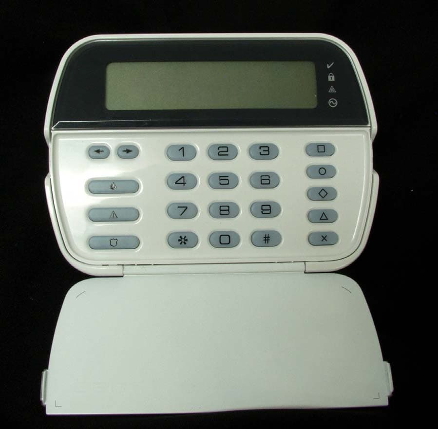
Click to zoom
Application Details
- Equipment Class
- CYY - Communications Receiver used w/Pt 15 Transmitter
- Date of Grant
- Apr 16, 2006
- Application Purpose
- Original Equipment
- Date of Application
- Apr 16, 2006
- Equipment Note
- ASK Receiver
- Frequency Range
- 433.92000000 - 433.92000000
- Country
- Canada
Documents & Files
Document Text
Text extracted from the exhibit documents filed with the FCC. Open a document above to read the original.
Users Manual
PK55XX RFK55XX-433 WARNING: Please refer to the System Installation Man- ual for information on limitations regarding product use and function and information on the limitations as to liability of the manufacturer. NOTE: These instructions shall be used in conjunction with the system Installation Manual of the Control Panel with which this equipment is intended to be used. Installation Instructions The PK55XX\RFK55XX keypads can be used on security systems with up to 64 zones. These keypads are compatible with the following DSC security systems: The RFK55XX keypads combine a standard PC5132 receiver with the respective PK55XX keypad. Specifications • Voltage rating: 12V DC nominal • Connects to control panel via 4-wire Keybus • 1 keypad zone input/PGM output* • Current draw: 50mA (standby) /125mA (maximum) • Optional tamper version • 5 programmable function keys • Ready (green LED), Armed (red LED), Trouble (yellow LED), AC (green LED) • Low temperature sensor • Frequency: 433.92MHz (RFK55XX-433 Only) • Upto 32 wireless zones (RFK55XX Only) NOTE: * Zone not to be programmed as Fire type or 24h type. Unpacking The Power keypad package includes the following parts: • One Power keypad• Keypad inner door labels • Four mounting screws• 1 tamper switch • 2 end-of-line resistors• 1 Installation Instructions Mounting You should mount the keypad where it is accessible to designated points of entry and exit. Once you have selected a dry and secure location, perform the following steps to mount the keypad. 1. Removing the keypad from the backplate for the first time. (a) Position the keypad as indicated below, insert screwdriver and rotate. 2. Removing the keypad from backplate once mounted. (a) Open door, holding it 90° to the keypad, as shown below. (b) Insert screwdriver into slot located under the door hinge and rotate the screwdriver. Wiring 1.Before wiring the unit, ensure that all power (AC transformer and battery) is disconnected from the control panel. 2.Connect the four Keybus wires from the control panel (red, black, yellow and green) to the keypad terminals. Refer to diagram: 3.If programmed as an input, you can connect a device - such as a door contact - to the ‘P/Z’ terminal of the keypad. This eliminates the need to run wires back to the control panel for the device. To connect the zone, run one wire from the device to the ‘P/Z’ terminal and the other wire from the device to the B (black) terminal. For powered devices, run the red wire to the R (positive) terminal and the black wire to the B (negative) terminal. When using end of line supervision, connect the zone according to one of the configurations outlined in your system’s Installation Manual. 4.If the ‘P/Z’ terminal is programmed as an output, the output fol- lows the PGM programmed in Section [080]. A small relay, buzzer or other DC operated device may be connected between the positive supply voltage and the ‘P/Z’ terminal (maximum load is 50mA). Applying Power Once all wiring is complete, apply power to the control panel: 1. Connect the battery leads to the battery. 2. Connect the AC transformer. For more information on control panel power specifications, see the control panel Installation Manual. Programming the Keypad There are several programming options available for the keypad. These are described below. Programming the keypad is similar to programming the rest of the system. When you are in the keypad programming sections, the keypad will display which options are turned on along the top of the display. To turn an option on or off, press the number correspond- ing to the option on the num- ber pad. The numbers of the options that are currently turned ON will be displayed. For example, if options 1 and 4 are on, the display will look like this on the different key- pad displays: For information on program- ming the rest of your security system, please refer to your system’s Installation Manual. Programming LCD Labels All LCD programming is done per keypad. If more than one LCD key- pad is present on the system, labels programmed at one keypad can be broadcast to all other LCD keypads. Perform the following proce- dure in order to broadcast labels: Step 1 - Program one LCD keypad completely. Step 2 - Make sure all LCD keypads are connected to the Keybus. Step 3 - Enter Installer’s Programming, then enter section [998] at the keypad that was programmed. The keypad will now broadcast all the information programmed to all the other LCD keypads on the system. Step 4 - When the keypad is finished press the [#] key to exit. NOTE: Label brodcast from this keypad is only compatible with other PK5500 and RFK5500 Keypads. Installation Instructions 123 456 78 0 * # 9 RFK5500 PK5500 123 456 78 0 * # 9 RFK5501 PK5501 123 456 78 0 * # 9 RFK5508 PK5508 123 456 78 0 * # 9 RFK5516 PK5516 •PC580/PC585•PC1555MX/PC1565•PC1616/PC1832/PC1864 •PC5005•PC5008•PC5010 •PC5015•PC5016•PC5020 Disasembling (Free-standing) 1. Insert the screwdriver into slot at an angle and push 3. Repeat steps 1. and 2. for left side 2. Rotate 90° 3. Repeat steps 1. and 2. for right sid e Disasembling (Wall-Mounted) 1. Insert the screwdriver into slot at an angle and push 2. Rotate 90° PK55XX\RFK55XX RED BLK YEL GRN To zone or PGM out put R B Y G P/Z FCC Compliance Statement Caution: Changes or modifications not expressly approved by Digital Security Controls could void your authority to use this equipment. This equipment generates and uses radio frequency energy and if not installed and used properly, in strict accordance with the manufacturer’s instructions, may cause interference to radio and television reception. It has been type tested and found to comply with the limits for Class B device in accordance with the specifications in Subpart “B” of Part 15 of FCC Rules, which are designed to provide reasonable protection against such interference in any residential installation. However, there is no guarantee that interference will not occur in a particular installati…
Text truncated - open the document above for the full version.
ID Label/Location Info
Top of the unit shows the label location (actual size) 18007998 Rev 001 RFK5500-433 FCC/IC/UL/ULC Label File: [18007998R001_RFK5500-433_FCC-IC-UL-ULC_LB.eps] April 6, 2006 10 mm 78 mm Template: [TEMPLATE_UL-ULC_LABELS.eps] Feb-14-05 (updated Jun-10-05, Dec-22-05) Label shown 200% of actual size Label 18007998 Rev 001 Colour: Pantone Process Black Material: CLEAR UL approved self-adhesive Mylar type material Cutting: Tolerance +/- 0.010” Dashed line indicates cutting - will not print NOTE: All UL and ULC Labels shall be printed by a UL Listed printing facilit y. The issue number (when applica ble) shall be requested from ULC Label Ordering Department (Phone: 416-757-5250) by the printing facility at the time of printing. NOTES: 1. All items must be RoHS compliant, lead-free. 2. Markings on label must be PERMANENT. 3. Indelible Ink - Conductive inks may not be used C M Y CM MY CY CMY K Proof-1_18007998R001_RFK5500-433_FCC-IC-UL-ULC_LB.pdf 4/7/2006 9:58:16 AMProof-1_18007998R001_RFK5500-433_FCC-IC-UL-ULC_LB.pdf 4/7/2006 9:58:16 AM
Test Report
FCC Part 15 Subpart B, March 2005 Test Report: 6W64372 Applicant: Digital Security Controls, a Division of Tyco Safety Products Canada Ltd. 3301 Langstaff Road Concord, Ontario L4K 4L2 Apparatus: RFK5500-433 Keypad RFK5501-433 Keypad RFK5508-433 Keypad RFK5516-433 Keypad FCC ID: F5306RFK55XX4 In Accordance With: FCC Part 15 Subpart B, 15.107 and 15.109 Unintentional Radiators Tested By: Nemko Canada Inc. 303 River Road Ottawa, Ontario K1V 1H2 Authorized By: Jin Xu, Wireless Specialist Date: April 13, 2006 Total Number of Pages: 17 Nemko Canada Inc. REPORT SUMMARY Report Number: 6W64372 FCC ID: F5306RFK55XX4 Specification: FCC Part 15 Subpart B Page 2 of 17 Report Summary These tests were conducted on a sample of the equipment for the purpose of demonstrating compliance with Part 15, Subpart B. Radiated tests were conducted in accordance with ANSI C63.4-2003. Radiated emissions are made on an open area test site. A description of the test facility is on file with the FCC. The assessment summary is as follows: Apparatus Assessed: RFK5500-433 Keypad, RFK5501-433 Keypad, RFK5508-433 Keypad, RFK5516-433 Keypad Specification: FCC Part 15 Subpart B, 15.107 and 15.109 Compliance Status: Complies Exclusions: None Non-compliances: None Report Release History: Original Release Author: Jason Nixon, Telecom Specialist Note that the results contained in this report relate only to the items tested and were obtained in the period between the date of initial receipt of samples and the date of issue of the report. This test report has been completed in accordance with the requirements of ISO/IEC 17025. Nemko Canada Inc. authorizes the applicant to reproduce this report provided it is reproduced in its entirety and for use by the company’s employees only. Any use which a third party makes of this report, or any reliance on or decisions to be made based on it, are the responsibility of such third parties. Nemko Canada Inc. accepts no responsibility for damages, if any, suffered by any third party as a result of decisions made or actions based on this report. Nemko Canada Inc. REPORT SUMMARY Report Number: 6W64372 FCC ID: F5306RFK55XX4 Specification: FCC Part 15 Subpart B Page 3 of 17 TABLE OF CONTENTS Report Summary......................................................................................................................................... 2 Section 1 : Equipment Under Test............................................................................................................. 4 1.1 Product Identification .................................................................................................................................4 1.2 Samples Submitted for Assessment............................................................................................................4 1.3 Theory of Operation ...................................................................................................................................4 1.4 Technical Specifications of the EUT ..........................................................................................................4 1.5 Block Diagram of the EUT.........................................................................................................................5 Section 2 : Test Conditions......................................................................................................................... 6 2.1 Specifications .............................................................................................................................................6 2.2 Deviations From Laboratory Test Procedures ............................................................................................6 2.3 Test Environment .......................................................................................................................................6 2.4 Test Equipment...........................................................................................................................................6 Section 3 : Observations ............................................................................................................................. 7 3.1 Modifications Performed During Assessment ............................................................................................7 3.2 Record Of Technical Judgements ...............................................................................................................7 3.3 EUT Parameters Affecting Compliance .....................................................................................................7 3.4 Test Deleted................................................................................................................................................7 3.5 Additional Observations .............................................................................................................................7 Section 4 : Results Summary ..................................................................................................................... 8 4.1 FCC Part 15 Subpart C : Test Results ........................................................................................................9 Appendix A : Test Results ........................................................................................................................ 10 Clause 15.107(a) Conducted Emissions ..............................................................................................................10 Clause 15.109(a) Radiated Emissions..................................................................................................................14 Appendix B : Setup Photographs ............................................................................................................ 15 Appendix C : Block Diagram of Test Setups .......................................................................................... 17 Nemko Canada Inc. SECTI…
Text truncated - open the document above for the full version.
Test Report
RSS GEN, Issue 1 - Rx : September 2005 Test Report: 6W64372.1 Applicant: Digital Security Controls, a Division of Tyco Safety Products Canada Ltd. 3301 Langstaff Road Concord, Ontario L4K 4L2 Apparatus: RFK5500-433 Keypad RFK5501-433 Keypad RFK5508-433 Keypad RFK5516-433 Keypad In Accordance With: RSS-GEN, Issue 1 Receiver Tests Tested By: Nemko Canada Inc. 303 River Road Ottawa, Ontario K1V 1H2 IC OATS Reference No.: IC 2040-1 Authorized By: Jin Xu, Wireless Specialist Date: April 13, 2006 Total Number of Pages: 17 Nemko Canada Inc. REPORT SUMMARY Report Number: 6W64372.1 Specification: RSS GEN, Issue 1 Page 2 of 17 Report Summary These tests were conducted on a sample of the equipment for the purpose of demonstrating compliance with Industry Canada RSS-GEN. Radiated tests were conducted in accordance with ANSI C63.4-2003. Radiated emissions are made on an open area test site. A description of the test facility is on file with Industry Canada. The assessment summary is as follows: Apparatus Assessed: RFK5500-433 Keypad RFK5501-433 Keypad RFK5508-433 Keypad RFK5516-433 Keypad Specification: RSS-GEN, Issue 1 Compliance Status: Complies Exclusions: None Non-compliances: None Report Release History: Original Release Author: Jason Nixon, Telecom Specialist Note that the results contained in this report relate only to the items tested and were obtained in the period between the date of initial receipt of samples and the date of issue of the report. This test report has been completed in accordance with the requirements of ISO/IEC 17025. Nemko Canada Inc. authorizes the applicant to reproduce this report provided it is reproduced in its entirety and for use by the company’s employees only. Any use which a third party makes of this report, or any reliance on or decisions to be made based on it, are the responsibility of such third parties. Nemko Canada Inc. accepts no responsibility for damages, if any, suffered by any third party as a result of decisions made or actions based on this report. Nemko Canada Inc. REPORT SUMMARY Report Number: 6W64372.1 Specification: RSS GEN, Issue 1 Page 3 of 17 TABLE OF CONTENTS Report Summary......................................................................................................................................... 2 Section 1 : Equipment Under Test............................................................................................................. 4 1.1 Product Identification .................................................................................................................................4 1.2 Samples Submitted for Assessment............................................................................................................4 1.3 Theory of Operation ...................................................................................................................................4 1.4 Technical Specifications of the EUT ..........................................................................................................4 1.5 Block Diagram of the EUT.........................................................................................................................5 Section 2 : Test Conditions......................................................................................................................... 6 2.1 Specifications .............................................................................................................................................6 2.2 Deviations From Laboratory Test Procedures ............................................................................................6 2.3 Test Environment .......................................................................................................................................6 2.4 Test Equipment...........................................................................................................................................6 Section 3 : Observations ............................................................................................................................. 7 3.1 Modifications Performed During Assessment ............................................................................................7 3.2 Record Of Technical Judgements ...............................................................................................................7 3.3 EUT Parameters Affecting Compliance .....................................................................................................7 3.4 Test Deleted................................................................................................................................................7 3.5 Additional Observations .............................................................................................................................7 Section 4 : Results Summary ..................................................................................................................... 8 4.1 IC RSS-GEN, Issue 1 : Test Results...........................................................................................................9 Appendix A : Test Results ........................................................................................................................ 10 Clause 7.2.2 Transmitter and Receiver AC Power Lines Conducted Emission Limits .......................................10 Clause 7.2.3.2 Receiver Spurious Emissions (Radiated) .....................................................................................14 Appendix B : Setup Photographs ............................................................................................................ 15 Appendix C : Block Diagram of Test Setups .......................................................................................... 17 Nemko Canada Inc. SECTION 1 : EQUIPMENT UNDER TEST Report Number: 6W64372.1 Specification: RSS GEN, Issue 1 Page 4 of 17 Section 1 : Equipmen…
Text truncated - open the document above for the full version.
Test Setup Photos
Conducted Emissions Setup: Spurious Emissions Setup:
Contact Information
Applicant
Dan Nita(Approvals Manager)
Test Firm
Nemko Canada Inc. (Ottawa)Charles Neal
Technical Specifications
| # | Rule Parts | Frequency Range | Power Output |
|---|---|---|---|
| 1 | 15B | 433.92 MHz - 433.92 MHz | - |
Other Applications from Tyco Safety Products Canada Ltd.

F53252RFLOCK
Jun 05, 2026IQ Lock-PGP, IQ Lock Touch-PGP
Equipment Class
DTS - Digital Transmission System
F5325PGPDC9
Apr 27, 2026PowerG wireless transceiver module
Equipment Class
DSS - Part 15 Spread Spectrum Transmitter
F5325LC203424
Dec 17, 2025Dual Technology Motion Sensor
Equipment Class
FDS - Part 15 Field Disturbance SensorF5324PGPIO9
Dec 04, 2024Wireless Input / Output (I/O) w/wo contact
Equipment Class
DSS - Part 15 Spread Spectrum Transmitter
F5323PGP9934P
Jan 16, 2024Wireless Motion detector with integrated camera
Equipment Class
DSS - Part 15 Spread Spectrum Transmitter