F5306WS4904Wireless Passive Infrared Motion Detector
Tyco Safety Products Canada Ltd.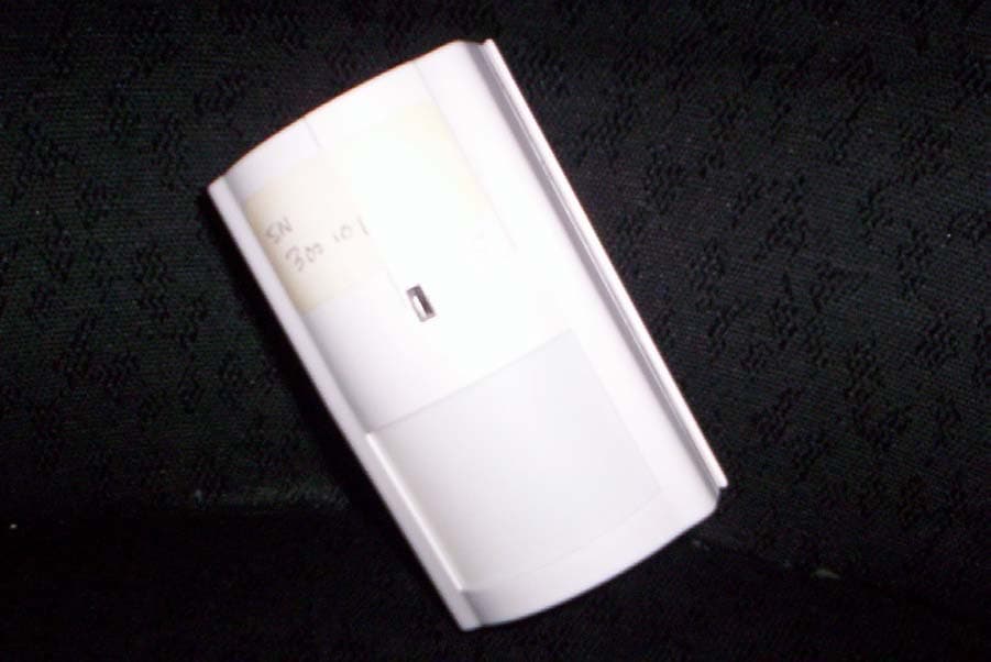
Click to zoom
Application Details
- Equipment Class
- DSC - Part 15 Security/Remote Control Transmitter
- Date of Grant
- Feb 09, 2006
- Application Purpose
- Original Equipment
- Date of Application
- Feb 09, 2006
- Equipment Note
- Wireless Passive Infrared Motion Detector
- Frequency Range
- 433.92000000 - 433.92000000
- Country
- Canada
Documents & Files
Document Text
Text extracted from the exhibit documents filed with the FCC. Open a document above to read the original.
Users Manual
WS4904/WS4904P - Inst allation Instructions The WS4904/WS4904P detector is designed to combine the convenienc e of a wireless detector with effective and reliable detection of human motion as well as good protection against the nuisance alarms associated with pets weighing up to 60 lbs (27.3kg). Installing the DetectorThe WS4904/WS4904P detector provides effective immunity to single or multiple pets whose total combined weight does not exceed 60 lbs. (27.3kg) when installed and configured in the following manner. LocationSelect a detector location that will prov ide the coverage required and will allow the detector to be mounted a minimum of 6 ½ f t (1.95m) high and not higher than 10ft (3m) (7½ ft / 2.3m recommended). Consider the following to avoid false alarms:• Do not aim the detector at a stairwell to which a pet has access • Do not place furniture or objects higher than 3ft (0.9m) which a pet can climb onto (e.g. a cat on a couch), closer than 6ft ( 1.8m) from the detector • Mount the detector flat on a wall or in a corner. Do not angle it downwards or use mounting bracke ts with this detector when i t is used in conjunction with pets • Do not aim the detector at reflective surfaces such as mirrors or windows as this may distort the coverage pattern or reflect sunlight directly onto the detector • Avoid locations that are subject to direct hi gh air flow such as near an air duct outlet • Do not locate the detector near sources of moisture such as steam or oil • Do not limit the coverage by large obstructions in the detection area such as plants or cabinets • For indoor use only (non-hazardous locations) NOTE: No detector should be mounted without first performing a module placement test to determine that it is in range of the wire- less receiver. See the Placement Test instructions in the Instru ction Sheet for your receiver, or in the Installation Manual fo r your sys- tem.When a location has been selected, remove the plastic from the mounting holes and locate the backplate on the wall and mark screw locations. It is suggested that wall anchors be used for all screw locations. Secure the ba ckplate to the wall, and then secure the enrolled detector to its backplate.NOTE: Use only backplates marked as “Type-L”. Using any other bac kplates will result in the tamper switch being broken. Enrolling a WS4904/WS4904POn the back of the PIR housing, there will be a six-digit number. Please refer to your receiver Installation Manual for information on which serial number should be enrolled. Changing the Sensitivity SettingThe WS4904/WS4904P features “Fast” and “Slow” settings on jumper J1, which is used to configure the detector for the weight of the pet(s) and the environment. For an environment with a single pet whose weight does not exceed 30lbs (13.6kg) the jumper should be set to “Fast” setting. In an environment with single or multiple pets whose combined weight is greater than 30lbs (13.6kg) but not gr eater than 60 lbs. (27.3kg), the jumper must be set to the “Slow” setting. When the detector is mounted 6 ½ ft to 7 ½ ft high (1.95 to 2. 3 m) or there is the possibility of the pet getting higher than 4ft (1.2 m ) the "slow" setting must be used. To change the setting fro m Slow to Fast, move the jumper over one pi n, as shown in the diagram. High Traffic Shutdown ModeTo prolong battery life, the motion detector uses a feature called High Traffic Shutdown. When mo tion is detected, the device w ill transmit to the receiver and will then shut down for three minutes. If motion is detected again during the shutdown time, the unit will not transmit the event to the receiver. The detector will th us remain in the shutdown mode until thre e minutes after the first motion detected w as transmitted. The detector will transmit detected motion every three minutes.The High Traffic Shutdown Mode affects testing the motion detector in two ways:When performing the module placement test , the unit must be tampered by removing the unit from the backplate and replacing it. The placement test cannot be performed by creating motion in front of the device. When performing a system test , the unit must be left idle for three minutes befo re testing can be performed. Once three minutes has passed, create motion in front of the detector to see if the de vice is both detecting motion and transmitting to the receiver. NOTE: Refer to the PC5132 or the System Installation Instructions for UL/ULC requirements. For UL/ULC installations where the WS4904/WS4904P is used on entry or exit delay zones, the entry delay must not be longer than 39 seconds, and the exit delaymust not be longer than 54 seconds. Motion Detector Transmission DelayA motion detector transmission is always delayed by six seconds. This is necessary to prevent false alarms caused by a motion s ensor trans- mitting before a delay zone has a chance to report. This six-second delay cannot be altered or disabled. Walk Test ModeThe motion detector has a walk test mode which will activate an LED for testing purposes. During normal operation, the LED will not turn on. To put the detector in walk test mode, create a tamper by removing the detector from its backplate and then replacing it. Each time the detector senses motion, it will flash the red LED. 6 se conds after motion is detected, the detector will send a signal to the receiver. The detector will be in walk test mode until it has se nt 10 transmissions. To verify the pet immunity of the detector place the animal(s) wi thin the coverage area and then move out of the zone. Encourag e the pet to move around as it normally would and ensure that it moves across the detection pattern of the detector. Verify that no a larm is initiated. To test for catch performance of humans, create motion in the entire area where coverage is desired by walking perp endicular to the lens pattern. Should the coverage be incomplete, readjust or relocate the detector. NOTE: Pet Immunity not verified by UL.. NOTE: The Walk…
Text truncated - open the document above for the full version.
Cover Letter(s)
January 3, 2006 Equipment Authorisation Division Federal Communications Commission 7435 Oakland Mills Road Columbia, MD 21046 FCC ID: F5306WS4904 Product Name: WS4904, WS4904P Request for Confidentiality Pursuant to Sections 0.457 and 0.459 of the commissions rules, we hereby request that the following documents be held confidential: • Schematics • Block diagram • Operational description These materials contain trade secrets and proprietary information and are not customarily released to the public. The public disclosure of this information might be harmful to the company and provide unjustified benefits to our competitors. Dated this 3 rd Day ofJanuary 20 06 By: Dan Nita Signature Printed Title: Approval Manager On behalf of : Digital Security Controls Telephone: 905-760-3000, Ext. 2706
Cover Letter(s)
January 12, 2006 To Whom It May Concern: The DSC WS4904 and WS4904P Wireless Motion Detectors are built using the same PCB assembly (based on UA523 Rev. 02), plastic enclosure and PIR sensor and have similar functionality. The only difference between the two models is the Pet Immune type of lens used for the WS4904P model. This type of lens is ensuring a greater immunity to pet movements in the protection-covered area in order to reduce false alarms. Respectfully yours, Dan Nita Approvals Manager 1
ID Label/Location Info
18007945 Rev 001 WS4904 FCC/IC Label File: [18007945R001_WS4904_FCC-IC_LB.eps] January 11, 2006 Colour: Pantone Process Black Material: White UL approved self-adhesive Mylar type material Lamination: Top lamination (e.g. 1F9) Adhesive: Permanent adhesive backed with protective liner (e.g. RH1) Cutting: Tolerance +/- 0.010 ” Dashed line indicates cutting - will not print NOTES: 1. All items must be RoHS compliant, lead-free. 2. Markings on label must be PERMANENT. 3. Indelible Ink - Conductive inks may not be used 48 mm 18 mm Label shown 200% of actual size Rear housing of the unit showing placement of label (actual size) L E B A L L E D O M 1 × 3V EVEREADY LITHIUM ENERGI ZER NO. EL123AP __ + L E B A L R E B M U N L A I R E S C M Y CM MY CY CMY K Proof-1_18007945R001_WS4904_FCC-IC_LB.pdf 1/11/2006 3:05:21 PMProof-1_18007945R001_WS4904_FCC-IC_LB.pdf 1/11/2006 3:05:21 PM
Test Report
FCC Part 15 Subpart C, 15.231 : February 2005 Test Report: 6W58612.1 Issue 2 Applicant: Digital Security Controls, a division of Tyco Safety Products Canada Ltd. 3301 Langstaff Road Concord, ON L4K 4l2 Canada Apparatus: Wireless 433MHz Pet Immune PIR M/N #WS4904 and WS4904P FCC ID: F5306WS4904 In Accordance With: FCC Part 15 Subpart C, 15.231 Periodic operation in the band 40.66-40.70MHz and above 70 MHz. Tested By: Nemko Canada Inc. 303 River Road Ottawa, Ontario K1V 1H2 Authorized By: Sim Jagpal, Resource Manager Date: February 9, 2006 Total Number of Pages: 18 Nemko Canada Inc. REPORT SUMMARY Report Number: 6W58612.1 Issue 2 FCC ID: F5306WS4904 Specification: FCC Part 15 Subpart C, 15.231 Page 2 of 18 Report Summary These tests were conducted on a sample of the equipment for the purpose of demonstrating compliance with Part 15, Subpart C. Radiated tests were conducted in accordance with ANSI C63.4-2003. Radiated emissions are made on an open area test site. A description of the test facility is on file with the FCC. The assessment summary is as follows: Apparatus Assessed: Wireless 433MHz Pet Immune PIR, M/N #WS4904 and WS4904P Specification: FCC Part 15 Subpart C, 15.231 Compliance Status: Complies Exclusions: None Non-compliances: None Report Release History: Issue 2 – Revised clause 15.231(a) Author: Daniel Hynes, EMC Specialist Note that the results contained in this report relate only to the items tested and were obtained in the period between the date of initial receipt of samples and the date of issue of the report. This test report has been completed in accordance with the requirements of ISO/IEC 17025. Nemko Canada Inc. authorizes the applicant to reproduce this report provided it is reproduced in its entirety and for use by the company’s employees only. Any use which a third party makes of this report, or any reliance on or decisions to be made based on it, are the responsibility of such third parties. Nemko Canada Inc. accepts no responsibility for damages, if any, suffered by any third party as a result of decisions made or actions based on this report. Nemko Canada Inc. REPORT SUMMARY Report Number: 6W58612.1 Issue 2 FCC ID: F5306WS4904 Specification: FCC Part 15 Subpart C, 15.231 Page 3 of 18 TABLE OF CONTENTS Report Summary......................................................................................................................................... 2 Section 1: Equipment Under Test.............................................................................................................. 4 1.1 Product Identification .................................................................................................................................4 1.2 Samples Submitted for Assessment............................................................................................................4 1.3 Theory of Operation ...................................................................................................................................4 1.4 Technical Specifications of the EUT ..........................................................................................................5 1.5 Block Diagram of the EUT.........................................................................................................................5 Section 2: Test Conditions.......................................................................................................................... 6 2.1 Specifications .............................................................................................................................................6 2.2 Deviations From Laboratory Test Procedures ............................................................................................6 2.3 Test Environment .......................................................................................................................................6 2.4 Test Equipment...........................................................................................................................................6 Section 3: Observations .............................................................................................................................. 7 3.1 Modifications Performed During Assessment ............................................................................................7 3.2 Record Of Technical Judgements ...............................................................................................................7 3.3 EUT Parameters Affecting Compliance .....................................................................................................7 3.4 Test Deleted................................................................................................................................................7 3.5 Additional Observations .............................................................................................................................7 Section 4: Results Summary ...................................................................................................................... 8 4.1 FCC Part 15 Subpart C: Test Results .........................................................................................................9 Appendix A: Test Results ......................................................................................................................... 10 Clause 15.231(a) Conditions for intentional radiators to comply with periodic operation ..................................10 Clause 15.231(b) Radiated Emissions .................................................................................................................12 Clause 15.231(c) 20dB Bandwidth ......................................................................................................................16 Appendix B: Setup Photographs ..................................................................................................…
Text truncated - open the document above for the full version.
Test Setup Photos
Radiated Emissions
Contact Information
Applicant
Dan Nita(Approvals Manager)
Technical Contact
Digital Security ControlsDan Nita
[email protected]905 760 3000
3301 Langstaff Road · Concord · Canada
Non-Technical Contact
Digital Security ControlsDan Nita
[email protected]905 760 3000
Test Firm
Nemko Canada Inc. (Ottawa)Charles Neal
Technical Specifications
| # | Rule Parts | Frequency Range | Power Output |
|---|---|---|---|
| 1 | 15.231 | 433.92 MHz - 433.92 MHz | - |
Other Applications from Tyco Safety Products Canada Ltd.

F53252RFLOCK
Jun 05, 2026IQ Lock-PGP, IQ Lock Touch-PGP
Equipment Class
DTS - Digital Transmission System
F5325PGPDC9
Apr 27, 2026PowerG wireless transceiver module
Equipment Class
DSS - Part 15 Spread Spectrum Transmitter
F5325LC203424
Dec 17, 2025Dual Technology Motion Sensor
Equipment Class
FDS - Part 15 Field Disturbance SensorF5324PGPIO9
Dec 04, 2024Wireless Input / Output (I/O) w/wo contact
Equipment Class
DSS - Part 15 Spread Spectrum Transmitter
F5323PGP9934P
Jan 16, 2024Wireless Motion detector with integrated camera
Equipment Class
DSS - Part 15 Spread Spectrum Transmitter