F5306WS4945Door Window Contact
Tyco Safety Products Canada Ltd.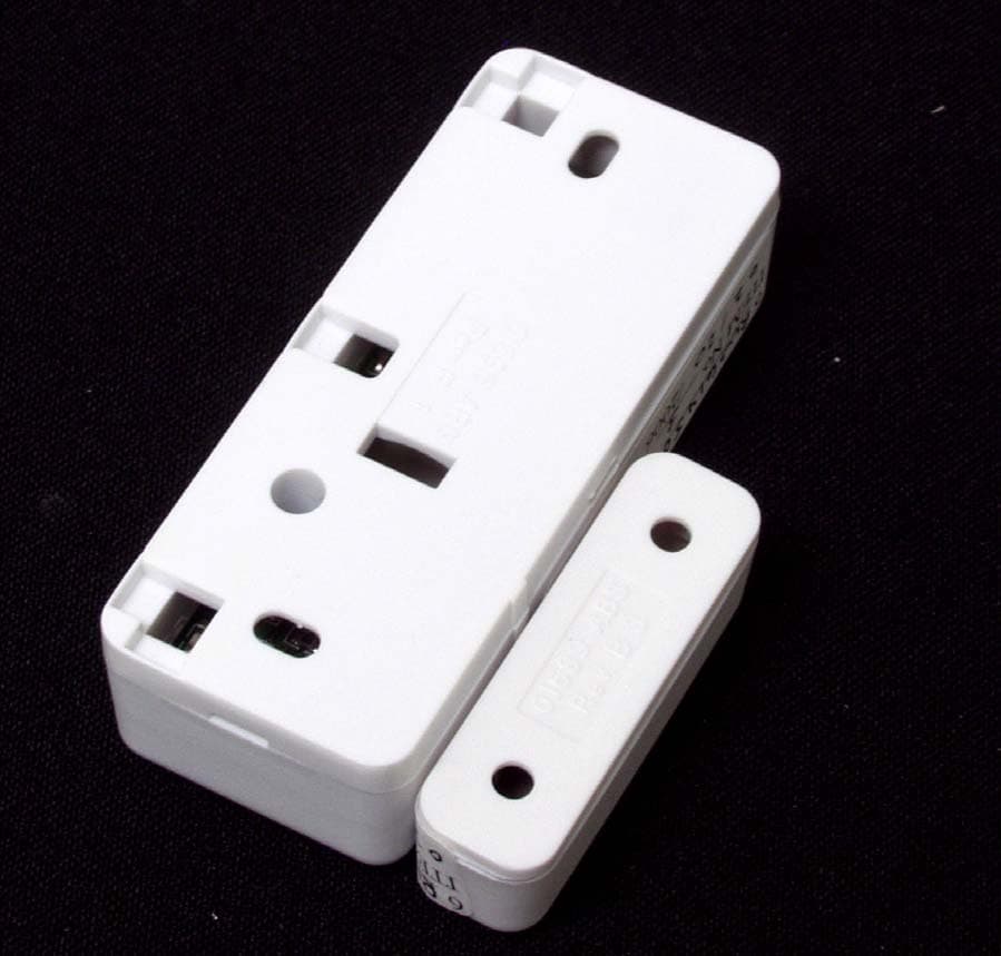
Click to zoom
Application Details
- Equipment Class
- DSC - Part 15 Security/Remote Control Transmitter
- Date of Grant
- Mar 07, 2006
- Application Purpose
- Original Equipment
- Date of Application
- Mar 07, 2006
- Equipment Note
- Door Window Contact
- Frequency Range
- 433.92000000 - 433.92000000
- Country
- Canada
Documents & Files
Document Text
Text extracted from the exhibit documents filed with the FCC. Open a document above to read the original.
Users Manual
WS4945Wireless Door/Window ContactPowering the WS4945For your added convenience, the WS4945 comes with th e battery pre-installed. To activate, hold the WS4945 firmly in one hand and pull the plastic tab in the direction indicated. Locate TransmitterSelect the location where the WS4945 is to be mounted. NOTE: RF signals can be affected by metal objects, including metal doors or large mirrors. Such locations should be av oided as they can interfere with proper operation. Enrolling, Programming and PlacementEnroll the WS4945 by programming the 6-digit serial nu mber (located on the WS 4945) into the receiver. Once the WS4945 is enrolled, you must perform a Modu le Placement test to ensu re the location you have chosen is suitable. Please refer to your receiver Installation Manual for details. Mounting the WS4945 and MagnetOnce you determine the proper location (see Enro lling, Programming and Placement), the WS4945 can be permanently mounted. NOTE: It is the responsibility of the installer to ensure that the WS4945 is securely mounted in the intended location.Using Provided Screws: Remove the back from the transmitte r. Mount the back housing of the WS4945, using the screws supplied, to the desired location.Using Adhesive Tape: Ensure that the surface is clean and dr y. Apply the tape to the back of the WS4945, press and hold firmly in the desired location for approximalty 10-15s. It can take up to 24h for the tape toreach maximum bonding strength.Align the magnet with the notched arrow on th e WS4945 housing (see Figure C). Mount the magnet a maximum of 5/8" (1.8cm) from the WS4945 by using th e provided tape or screws. If necessary use the spacers provided. Once the WS4945 and magnet are mo unted, open and close the window/door to ensure that none of the parts interfere with this move ment. Only one magnet can be used for each WS4945. NOTE: The adhesive tape is not to be used in UL Installations. Using External ContactsThe external contact terminals can be used to connect external contacts or other switches/devices to the uni-versal transmitter. Install the additional device as pe r the manufacturer instructions. Connect the device to the contact terminals of the WS4945. The input is normally closed and is not supervised. For all installations, the wires connecting the external device to the input terminals must not exceed 16" (40 cm) in length, provided that the resistance of the wi re does not exceed 100 Ohms . The contact and transmit- ter must also be in the same room. Only one contact can be used. If an external contact is used, do not install the magnet. Tamper SwitchOut of the box the WS4945 comes equipped with case tamper detection. If th e case is removed, the WS4945 will report a zone tamper to the control panel. For added security the WS4945 was designed toprovide wall tamper monitoring as well. Simply repl ace the short rubber actuator (see Figure D) with the longer one that is included. With this option, if th e case is opened or if the WS4945 is removed from it's location, a tamper will be sent to the control panel. It is strongly recommended that mounting screws be used when using the wall tamper option. Replacing the BatteryTo replace the battery, insert a flathead screwdriver into either side of the unit and carefully twist to separate the top and bottom plastic (see Figure A). Once separated, the battery will be visible (please refer to Figure B). Remove the old battery and install new battery, observing correct polarity. WAR NING! : Bat te ry may explode if mistreated. Do not rechar ge, disassemble or dispose of in fire. SpecificationsDimensions. . . . . . . . . . . . . . . . . . . . . . . . . . . . . . . . . . . . . . .7 5 mmx3 1 mmx 22 mm (2.9”x1.2”x0. 87 ”) OperatingTemperature . . . . . . . . . . . . . . . . . . . . . . . . . . . . . . . . . . . . . . . . . . . . 0 to 49 o C (32 to 120 o F) Operating Humidity . . . . . . . . . . . . . . . . . . . . . . . . . . . . . . . . . . . . . . . . . . . . . . . . . . . . . . 5 to 93% RH Operating Frequency . . . . . . . . . . . . . . . . . . . . . . . . . . . . . . . . . . . . . . . . . . . . . . . . . . . . . . . . 433MHz Battery . . . . . . . . . . . . . . . . . . . . . . . . . . . . . . . . . . . . . . . . . . . . . . . . . . Tekcell/Panasonic CR 2 Lithium Battery Life . . . . . . . . . . . . . . . . . . . . . . . . . . . . . . . . . . . . . . . . . . . . . . . . . . . . . . . . . . . . . . 5-8 years* * Not tested by UL/ULCCompatible with PC5132-433, PC4164- 433, NT9005-433, RF5501-433, RF5108-433 Installation Instructions WS4945Contact miniature pour Porte/FenêtreMise en marche du WS4945Pour vous faciliter la tâche, le WS4945 est livré avec la pile préinstallée. Pour activer, tenir fermement le WS4945 dans une main, et tirer la languette en plastic dans la direction indiquée. Emplacement de le WS4945Choisissez l’empl acement ou le WS4945 sera installé. REMARQUE : Le signal RF peut être affecté par des objets métalliques tels que des portes en métal ou des miroirs importants. Ce genre d’emplacement doit être évité car ces objets peuvent interférer avec le bon fonctionnement du dispositif. Attribution, Programmation et EmplacementAttribuer le WS4945 en programmant le récepteur avec le numéro de série à 6 chiffres (situé sur le WS4945). Une fois que le WS4945 est attribué, vous devez effectue r un essai de placement de module pour assurer que l'emplacement choisi convient. Pour de plus amples renseignem ents, veuillez consulter le manuel d'installation de votre récepteur.Installation de le WS4945 et de l'aimantUne fois que vous avez déterminé un emplacement approprié (voir Attribution, Programmation, Placement) le WS4945 peut être fixé de manière permanente. NOTE: Il est de la responsabilité de l'installateur de s'assurer que le WS4945 est solidement monté dans l'endroit prévu.Avec les vis fournies : Retirez la plaque arrière de le WS4945. Fixez, a l’emplacement désiré, la plaque arrière du coffret de le WS4945 avec les vis…
Text truncated - open the document above for the full version.
Cover Letter(s)
February 3, 2006 Equipment Authorisation Division Federal Communications Commission 7435 Oakland Mills Road Columbia, MD 21046 FCC ID: F5306WS4945 Product Name: WS4945NA Request for Confidentiality Pursuant to Sections 0.457 and 0.459 of the commissions rules, we hereby request that the following documents be held confidential: (List here the documents for which you are seeking confidentiality – for example ...) • Schematics • Block diagram • Operational description These materials contain trade secrets and proprietary information and are not customarily released to the public. The public disclosure of this information might be harmful to the company and provide unjustified benefits to our competitors. Dated this 3 rd Day of February 20 06 By: Dan Nita Signature Printed Title: Approval Manager On behalf of : Digital Security Controls Telephone: 905-760-3000, Ext. 2706
ID Label/Location Info
WS4945NA Digital Security Controls This device complies with Part 15 of the FCC Rules. Operation is sub- ject to the following two conditions: (1) This device may not cause harm- ful interference, and (2) this device must accept any interference re- ceived, including interference that may cause undesired operation. FCCID:F5306WS4945 IC:160A-06WS4945 MADEINCANADA 18011261Rev001 This Class B digital apparatus meets all requirements of the ICES-003. Cet appareil numérique de la classe B respecte toutes les exigences du ICES-003. FCC/ICES-003 Labeling for WS4945NA Wireless Mini Door/Window Contact File: [18011261_REV_001_WS4945NA_FCC-IC_LB_MYLAR.cdr] Dashed line indicates cut edge of label Label to be printed on UL Approved white self-adhesive Mylar type material Indelible black ink Label shown actual size Label shown 250% of actual size 35 mm 12.7 mm Side of the unit showing placement of label (Actual size) ® WS4945NA Digital Security Controls This device complies with Part 15 of the FCC Rules. Operation is sub- ject to the following two conditions: (1) This device may not cause harm- ful interference, and (2) this device must accept any interference re- ceived, including interference that may cause undesired operation. FCCID:F5306WS4945 IC:160A-06WS4945 MADEINCANADA 18011261 Rev001 This Class B digital apparatus meets all requirements of the ICES-003. Cet appareil numérique de la classe B respecte toutes les exigences du ICES-003. WS4945 Digital Security Controls Ltd. This device complies with Part 15 of the FCC Rules. Operation is sub- ject to the following two conditions: (1) This device may not cause harm- ful interference, and (2) this device must accept any interference re- ceived, including interference that may cause undesired operation. FCC ID:F5303WS4945 IC: 160A-WS4945 MADE IN CANADA 18011261 Rev 001 This Class B digital apparatus meets all requirements of the ICES-003. Cet appareil numérique de la classe B respecte toutes les exigences du ICES-003.
Parts List/Tune Up Info
Date: 02−17−06 [16:00]ENGINEERING BOMPage: 1 DSC Ltd (Mfg) Company : 651 −−−−−−−−−−−−−−−− Approval Date:−−−−−−−−−−−− −−−−−−−−−−−−−−−− Approval Date:−−−−−−−−−−−− −−−−−−−−−−−−−−−− Approval Date:−−−−−−−−−−−− −−−−+−−−−−−−−−−−−−−−−+−−−−−−−−−−−−−−−−−−−−−−−−−−−−−−−−+−−−−−−−−−−−−−−+−−−−−−+−−−−−−−−−+−−−−−−−−−+−−−−−−−−+−−−−−−−−−−−−−+−−−+−−−−−−−−+−−−−−− Pos.|Component |Description |Component Type| Revi−| Length | Width | No. of| Net Quantity|Un.|Extra |Sel | | | | sion| [m ] | [m ] | Units| | |Info |Code −−−−+−−−−−−−−−−−−−−−−+−−−−−−−−−−−−−−−−−−−−−−−−−−−−−−−−+−−−−−−−−−−−−−−+−−−−−−+−−−−−−−−−+−−−−−−−−−+−−−−−−−−+−−−−−−−−−−−−−+−−−+−−−−−−−−+−−−−−− E−Item: 73−01474WS4945 UA522 REV02 WIRELESS DRBOM Unit: 1ea Revision: 006LENH: RBR> 10|11002623 |WS4945 UA522 REV02 |E−Item | 001| | | | 1.0000|ea |PCB | LF 20|01000926 |0 OHM 1/10W 5% SMD (0603) |Item | 001| | | | 1.0000|ea |TOP | LF +−−−−−−−−−−−−−−−−−−−−−−−−−−−−−−−−−−−+ | Location | Net Quantity | +−−−−−−−−−−−−−−−−−−−−−−−−−−−−−−−−−−−+ | R9 | 1.0000 | +−−−−−−−−−−−−−−−−−−−−−−−−−−−−−−−−−−−+ 25|03000731 |1.5PF/50V 10% SMD (0603) NPO; |E−Item | 001| | | | 1.0000|ea |TOP | +−−−−−−−−−−−−−−−−−−−−−−−−−−−−−−−−−−−+ | Location | Net Quantity | +−−−−−−−−−−−−−−−−−−−−−−−−−−−−−−−−−−−+ | R8 | 1.0000 | +−−−−−−−−−−−−−−−−−−−−−−−−−−−−−−−−−−−+ 30|01000937 |100 OHM 1/10W 5% SMD ( |Item | 001| | | | 1.0000|ea |TOP | LF +−−−−−−−−−−−−−−−−−−−−−−−−−−−−−−−−−−−+ | Location | Net Quantity | +−−−−−−−−−−−−−−−−−−−−−−−−−−−−−−−−−−−+ | R1 | 1.0000 | +−−−−−−−−−−−−−−−−−−−−−−−−−−−−−−−−−−−+ 40|01000949 |1K OHM 1/10W 5% SMD (0 |Item | 001| | | | 4.0000|ea |TOP | LF +−−−−−−−−−−−−−−−−−−−−−−−−−−−−−−−−−−−+ | Location | Net Quantity | +−−−−−−−−−−−−−−−−−−−−−−−−−−−−−−−−−−−+ | R3 | 1.0000 | | R5 | 1.0000 | | R6 | 1.0000 | | R7 | 1.0000 | +−−−−−−−−−−−−−−−−−−−−−−−−−−−−−−−−−−−+ 50|03000627 |100NF/50V 10% SMD(0603) X7R |Item | | | | | 3.0000|ea |TOP | LF +−−−−−−−−−−−−−−−−−−−−−−−−−−−−−−−−−−−+ | Location | Net Quantity | +−−−−−−−−−−−−−−−−−−−−−−−−−−−−−−−−−−−+ | C13 | 1.0000 | | C14 | 1.0000 | | C3 | 1.0000 | +−−−−−−−−−−−−−−−−−−−−−−−−−−−−−−−−−−−+ 60|03000628 |100pF/50V 10% SMD (0603) |Item | | | | | 1.0000|ea |TOP | LF +−−−−−−−−−−−−−−−−−−−−−−−−−−−−−−−−−−−+ | Location | Net Quantity | +−−−−−−−−−−−−−−−−−−−−−−−−−−−−−−−−−−−+ | C10 | 1.0000 | +−−−−−−−−−−−−−−−−−−−−−−−−−−−−−−−−−−−+ 90|03000650 |82PF/50V 10% SMD (0603); MU |E−Item | 002| | | | 1.0000|ea |TOP | LF +−−−−−−−−−−−−−−−−−−−−−−−−−−−−−−−−−−−+ | Location | Net Quantity | +−−−−−−−−−−−−−−−−−−−−−−−−−−−−−−−−−−−+ | C7 | 1.0000 | +−−−−−−−−−−−−−−−−−−−−−−−−−−−−−−−−−−−+ 100|03000671 |330PF/50V 10% SMD (0603); M |Item | | | | | 2.0000|ea |TOP | LF Date : 02−17−06 [16:00] ENGINEERING BOM Page : 2 DSC Ltd (Mfg) Company : 651 −−−−+−−−−−−−−−−−−−−−−+−−−−−−−−−−−−−−−−−−−−−−−−−−−−−−−−+−−−−−−−−−−−−−−+−−−−−−+−−−−−−−−−+−−−−−−−−−+−−−−−−−−+−−−−−−−−−−−−−+−−−+−−−−−−−−+−−−−− Pos.|Component |Description |Component Type| Revi−| Length | Width | No. of| Net Quantity|Un.|Extra |Sel | | | | sion| [m ] | [m ] | Units| | |Info |Code E−Item : 73−01474 WS4945 UA522 REV02 WIRELESS DR BOM Unit: 1 ea Revision : 006 LENH: RBR> +−−−−−−−−−−−−−−−−−−−−−−−−−−−−−−−−−−−+ | Location | Net Quantity | +−−−−−−−−−−−−−−−−−−−−−−−−−−−−−−−−−−−+ | C15 | 1.0000 | | C6 | 1.0000 | +−−−−−−−−−−−−−−−−−−−−−−−−−−−−−−−−−−−+ 110|03000806 |220NF/16V 5% SMD (0603) X7R; M |Item | 001| | | | 1.0000|ea |TOP | LF +−−−−−−−−−−−−−−−−−−−−−−−−−−−−−−−−−−−+ | Location | Net Quantity | +−−−−−−−−−−−−−−−−−−−−−−−−−−−−−−−−−−−+ | C5 | 1.0000 | +−−−−−−−−−−−−−−−−−−−−−−−−−−−−−−−−−−−+ 120|03000734 |15PF/50V 10% SMD (0603) NPO; M |Item | | | | | 1.0000|ea |TOP | LF +−−−−−−−−−−−−−−−−−−−−−−−−−−−−−−−−−−−+ | Location | Net Quantity | +−−−−−−−−−−−−−−−−−−−−−−−−−−−−−−−−−−−+ | C9 | 1.0000 | +−−−−−−−−−−−−−−−−−−−−−−−−−−−−−−−−−−−+ 130|06001490 |MC9S08QG2 CFFE; MCU 2K FLASH |E−Item | 001| | | | 1.0000|ea |TOP | +−−−−−−−−−−−−−−−−−−−−−−−−−−−−−−−−−−−+ | Location | Net Quantity | +−−−−−−−−−−−−−−−−−−−−−−−−−−−−−−−−−−−+ | U2 | 1.0000 | +−−−−−−−−−−−−−−−−−−−−−−−−−−−−−−−−−−−+ 140|06001491 |TH72016; FSK/ASK RF TRANSMITTE |E−Item | 001| | | | 1.0000|ea |TOP | +−−−−−−−−−−−−−−−−−−−−−−−−−−−−−−−−−−−+ | Location | Net Quantity | +−−−−−−−−−−−−−−−−−−−−−−−−−−−−−−−−−−−+ | U1 | 1.0000 | +−−−−−−−−−−−−−−−−−−−−−−−−−−−−−−−−−−−+ 170|10000268 |100 NH 5% SMD(0603) CHIP INDUC |E−Item | 001| | | | 1.0000|ea |TOP | +−−−−−−−−−−−−−−−−−−−−−−−−−−−−−−−−−−−+ | Location | Net Quantity | +−−−−−−−−−−−−−−−−−−−−−−−−−−−−−−−−−−−+ | L1 | 1.0000 | +−−−−−−−−−−−−−−−−−−−−−−−−−−−−−−−−−−−+ 180|10000188 |22NH@300MA +/−10%; RDC=0.4OHM |Item | 001| | | | 1.0000|ea |TOP | +−−−−−−−−−−−−−−−−−−−−−−−−−−−−−−−−−−−+ | Location | Net Quantity | +−−−−−−−−−−−−−−−−−−−−−−−−−−−−−−−−−−−+ | L2 | 1.0000 | +−−−−−−−−−−−−−−−−−−−−−−−−−−−−−−−−−−−+ 190|14000889 |2−POS. MINI TERM. BLOCK W/BASE |E−Item | 001| | | | 1.0000|ea |TOP | +−−−−−−−−−−−−−−−−−−−−−−−−−−−−−−−−−−−+ | Location | Net Quantity | +−−−−−−−−−−−−−−−−−−−−−−−−−−−−−−−−−−−+ | TB1 | 1.0000 | +−−−−−−−−−−−−−−−−−−−−−−−−−−−−−−−−−−−+ 200|15000156 |SIOV−CN1206K14G; 14VRMS 10% |Item | | | | | 1.0000|ea |TOP | LF +−−−−−−−−−−−−−−−−−−−−−−−−−−−−−−−−−−−+ | Location | Net Quantity | +−−−−−−−−−−−−−−−−−−−−−−−−−−−−−−−−−−−+ | MV1 | 1.0000 | +−−−−−−−−−−−−−−−−−−−−−−−−−−−−−−−−−−−+ Date : 02−17−06 [16:00] ENGINEERING BOM Page : 3 DSC Ltd (Mfg) Company : 651 −−−−+−−−−−−−−−−−−−−−−+−−−−−−−−−−−−−−−−−−−−−−−−−−−−−−−−+−−−−−−−−−−−−−−+−−−−−−+−−−−−−−−−+−−−−−−−−−+−−−−−−−−+−−−−−−−−−−−−−+−−−+−−−−−−−−+−−−−− Pos.|Component |Description |Component Type| Revi−| Length | Width | No. of| Net Quantity|Un.|Extra |Sel | | | | sion| [m ] | [m ] | Units| | |Info |Code E−Item : 73−01474 WS4945 UA522 REV02 WIRELESS DR BOM Unit: 1 ea Revision : 006 LENH: RBR> 210|16000294 |MDSM−4R 7.5−10 AT; REED SWITCH |E−Item | 001| | | | 1.0000|ea |TOP | LF +−−−−−−−−−−−−−−−−−−−−−−−−−−−−−−−−−−−+ | Location | Net Quantity | +−−−−−−−−−−−−−−−−−−−−−−−−−−−−−−−−−−−+ | SW2 | 1.0000 | +−−−−−−−−−−−−−−−−−−−−−−−−−−−−−−−−−−−+ 220|22000235 |13.56MHZ XTAL; 20PPM@25C ESR=4 |E−Item | 001| | | | 1.0000|ea |TOP | LF +−−−−−−−−−−−−−−−−−−−−−−−−−−−−−−−−−−−+ | Location |…
Text truncated - open the document above for the full version.
Test Report
FCC Part 15 Subpart C, 15.231 : February 2005 Test Report: 6W61450 Applicant: Digital Security Controls, a Division of Tyco Safety Products Canada Ltd. 3301 Langstaff Road, Concord, Ontario L4K 4L2 Apparatus: WS4945NA FCC ID: F5306WS4945 In Accordance With: FCC Part 15 Subpart C, 15.231 Periodic operation in the band 40.66-40.70MHz and above 70 MHz. Tested By: Nemko Canada Inc. 303 River Road Ottawa, Ontario K1V 1H2 Authorized By: Jin Xu, Wireless Specialist Date: March 6, 2006 Total Number of Pages: 18 Nemko Canada Inc. REPORT SUMMARY Report Number: 6W61450 FCC ID: F5306WS4945 Specification: FCC Part 15 Subpart C, 15.231 Page 2 of 18 Report Summary These tests were conducted on a sample of the equipment for the purpose of demonstrating compliance with Part 15, Subpart C. Radiated tests were conducted in accordance with ANSI C63.4-2003. Radiated emissions are made on an open area test site. A description of the test facility is on file with the FCC. The assessment summary is as follows: Apparatus Assessed: WS4945NA Specification: FCC Part 15 Subpart C, 15.231 Compliance Status: Complies Exclusions: None Non-compliances: None Report Release History: Original Release Author: Jason Nixon, Telecom Specialist Note that the results contained in this report relate only to the items tested and were obtained in the period between the date of initial receipt of samples and the date of issue of the report. This test report has been completed in accordance with the requirements of ISO/IEC 17025. Nemko Canada Inc. authorizes the applicant to reproduce this report provided it is reproduced in its entirety and for use by the company’s employees only. Any use which a third party makes of this report, or any reliance on or decisions to be made based on it, are the responsibility of such third parties. Nemko Canada Inc. accepts no responsibility for damages, if any, suffered by any third party as a result of decisions made or actions based on this report. Nemko Canada Inc. REPORT SUMMARY Report Number: 6W61450 FCC ID: F5306WS4945 Specification: FCC Part 15 Subpart C, 15.231 Page 3 of 18 TABLE OF CONTENTS Report Summary......................................................................................................................................... 2 Section 1 : Equipment Under Test............................................................................................................. 4 1.1 Product Identification .................................................................................................................................4 1.2 Samples Submitted for Assessment............................................................................................................4 1.3 Theory of Operation ...................................................................................................................................4 1.4 Technical Specifications of the EUT ..........................................................................................................5 1.5 Block Diagram of the EUT.........................................................................................................................5 Section 2 : Test Conditions......................................................................................................................... 6 2.1 Specifications .............................................................................................................................................6 2.2 Deviations From Laboratory Test Procedures ............................................................................................6 2.3 Test Environment .......................................................................................................................................6 2.4 Test Equipment...........................................................................................................................................6 Section 3 : Observations ............................................................................................................................. 7 3.1 Modifications Performed During Assessment ............................................................................................7 3.2 Record Of Technical Judgements ...............................................................................................................7 3.3 EUT Parameters Affecting Compliance .....................................................................................................7 3.4 Test Deleted................................................................................................................................................7 3.5 Additional Observations .............................................................................................................................7 Section 4 : Results Summary ..................................................................................................................... 8 4.1 FCC Part 15 Subpart C : Test Results ........................................................................................................9 Appendix A : Test Results ........................................................................................................................ 10 Clause 15.209(a) Radiated Emissions within Restricted Bands ..........................................................................10 Clause 15.231(a) Conditions for intentional radiators to comply with periodic operation ..................................11 Clause 15.231(b) Radiated Emissions .................................................................................................................13 Clause 15.231(c) 20dB Bandwidth ......................................................................................................................16 Appendix B : Setup Photographs .......................................................................................................…
Text truncated - open the document above for the full version.
Contact Information
Applicant
Dan Nita(Approvals Manager)
Test Firm
Nemko Canada Inc. (Ottawa)Charles Neal
Technical Specifications
| # | Rule Parts | Frequency Range | Power Output |
|---|---|---|---|
| 1 | 15.231 | 433.92 MHz - 433.92 MHz | - |
Other Applications from Tyco Safety Products Canada Ltd.

F53252RFLOCK
Jun 05, 2026IQ Lock-PGP, IQ Lock Touch-PGP
Equipment Class
DTS - Digital Transmission System
F5325PGPDC9
Apr 27, 2026PowerG wireless transceiver module
Equipment Class
DSS - Part 15 Spread Spectrum Transmitter
F5325LC203424
Dec 17, 2025Dual Technology Motion Sensor
Equipment Class
FDS - Part 15 Field Disturbance SensorF5324PGPIO9
Dec 04, 2024Wireless Input / Output (I/O) w/wo contact
Equipment Class
DSS - Part 15 Spread Spectrum Transmitter
F5323PGP9934P
Jan 16, 2024Wireless Motion detector with integrated camera
Equipment Class
DSS - Part 15 Spread Spectrum Transmitter