F5307GS3060GSM Alarm Communicator
Tyco Safety Products Canada Ltd.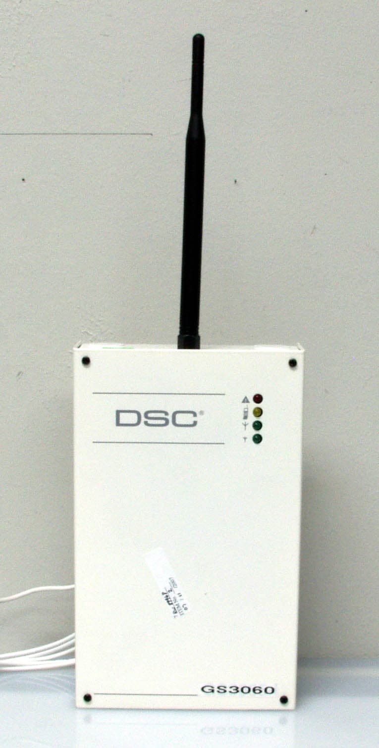
Click to zoom
Application Details
- Equipment Class
- PCB - PCS Licensed Transmitter
- Date of Grant
- Jul 25, 2007
- Application Purpose
- Original Equipment
- Date of Application
- Jul 25, 2007
- Equipment Note
- GSM Alarm Communicator
- Frequency Range
- 1850.20000000 - 1909.80000000
- Country
- Canada
Documents & Files
Document Text
Text extracted from the exhibit documents filed with the FCC. Open a document above to read the original.
Users Manual
GS3060 GSM-GPRS INTERFACE WARNING: This manual contains information on limitations regarding product use and function and information on the limitations as to liability of the manufacturer. INSTALLATION MANUAL FCC COMPLIANCE STATEMENT CAUTION: Changes or modifications not expressly approved by Digital Security Controls could void your authority to use this equipment. This equipment generates and uses radio frequency energy and if not installed and used properly, in strict accordance with the manufacturer's instructions, may cause interference to radio and television reception. It has been type tested and found to comply with the limits for Class B device in accordance with the specifications in Subpart "B" of Part 15 of FCC Rules, which are designed to provide reasonable protection against such interference in any residential installation. However, there is no guarantee that interference will not occur in a particular installation. If this equipment does cause interference to television or radio reception, which can be determined by turning the equipment off and on, the user is encouraged to try to correct the interference by one or more of the following measures: • Re-orient the receiving antenna • Relocate the alarm control with respect to the receiver • Move the alarm control away from the receiver • Connect the alarm control into a different outlet so that alarm control and receiver are on different circuits. If necessary, the user should consult the dealer or an experienced radio/ television technician for additional suggestions. The user may find the following booklet prepared by the FCC helpful: "How to Identify and Resolve Radio/Television Interference Problems". This booklet is available from the U.S. Government Printing Office, Washington, D.C. 20402, Stock # 004- 000-00345-4. IMPORTANT INFORMATION This equipment complies with Part 68 of the FCC Rules. On the side of this equipment is a label that contains, among other information, the FCC registration number and ringer equivalence number (REN) for this equipment. If requested, this number must be provided to the Telephone Company. GS3060 Product IdentifierUS: F53AL00BGS3060 REN:0.0B USOC Jack:RJ-31X Telephone Connection Requirements A plug and jack used to connect this equipment to the premises wiring and telephone network must comply with the applicable FCC Part 68 rules and requirements adopted by the ACTA. A compliant telephone cord and modular plug is provided with this product. It is designed to be connected to a compatible modular jack that is also compliant. See installation instructions for details. Ringer Equivalence Number (REN) The REN is used to determine the number of devices that may be connected to a telephone line. Excessive RENs on a telephone line may result in the devices not ringing in response to an incoming call. In most but not all areas, the sum of RENs should not exceed five (5.0). To be certain of the number of devices that may be connected to a line, as determined by the total RENs, contact the local Telephone Company. For products approved after July 23, 2001, the REN for this product is part of the product identifier that has the format. US: AAAEQ##TXXXX. The digits represented by ## are the REN without a decimal point (e.g., 03 is a REN of 0.3). For earlier products, the REN is separately shown on the label. Incidence of Harm If this equipment GS3060 causes harm to the telephone network, the telephone company will notify you in advance that temporary discontinuance of service may be required. But if advance notice is not practical, the Telephone Company will notify the customer as soon as possible. Also, you will be advised of your right to file a complaint with the FCC if you believe it is necessary. Changes in Telephone Company Equipment or Facilities The Telephone Company may make changes in its facilities, equipment, operations or procedures that could affect the operation of the equipment. If this happens the Telephone Company will provide advance notice in order for you to make necessary modifications to maintain uninterrupted service. Equipment Maintenance Facility If trouble is experienced with this equipment for repair or warranty information, please contact the facility indicated below. If the equipment is causing harm to the telephone network, the Telephone Company may request that you disconnect the equipment until the problem is solved. This equipment is of a type that is not intended to be repaired by the end user. DSC c/o APL Logistics, 757 Douglas Hill Rd., Lithia Springs, GA 30122 Additional Information Connection to party line service is subject to state tariffs. Contact the state public utility commission, public service commission or corporation commission for information. Alarm dialling equipment must be able to seize the telephone line and place a call in an emergency situation. It must be able to do this even if other equipment (telephone, answering system, computer modem, etc.) already has the telephone line in use. To do so, alarm dialling equipment must be connected to a properly installed RJ-31X jack that is electrically in series with and ahead of all other equipment attached to the same telephone line. Proper installation is depicted in the figure below. If you have any questions concerning these instructions, you should consult your telephone company or a qualified installer about installing the RJ-31X jack and alarm dialling equipment for you. Telephone Computer Telephone Telephone Fax Machine Alarm Dialing Equipment RJ-31X Jack Unused RJ-11 Jack Telephone Line Network Service Provider's Facilities Customer Premises Equipment and Wiring Unused RJ-11 Jack Network Demarcation Point Answering System Industry Canada Compliance Statement This Equipment meets the applicable Industry Canada Terminal Equipment Technical Specifications. This is confirmed by the registration number. The abbreviation, IC, before the registration number signifies that registration was performed …
Text truncated - open the document above for the full version.
Cover Letter(s)
July 10, 2007 Nemko Canada Inc 303 River Road Ottawa, Ontario, Canada K1V 1H2 Attn: Director of Certification Authority to Act as Agent On our behalf, I appoint Nemko Canada Inc., 303 River Road, Ottawa, Ontario, Canada K1V 1H2 to act as our agent in the preparation of this application for equipment certification. I certify that submitted documents properly describe the device or system for which equipment certification is sought. I also certify that each unit manufactured, imported or marketed, as defined in the Federal Communications Commission’s regulations will have affixed to it a label identical to that submitted for approval with this application. For instances where our authorized agent signs the application for certification on our behalf, I acknowledge that all responsibility for complying with the terms and conditions for certification, as specified by Nemko Canada Inc, still resides with Digital Security Controls, 3301 Langstaff Road, Concord, Ontario Canada L4K 4L2. Dated this 10 th Day ofJuly 20 07 Agency agreement expiration date: July 10, 2008 By: Dan Nita Signature Printed Title: Approvals Manager On behalf of : Digital Security Controls Telephone: 905-760-3000, Ext. 2706
Cover Letter(s)
July 10, 2007 Equipment Authorisation Division Federal Communications Commission 7435 Oakland Mills Road Columbia, MD 21046 FCC ID: F5307GS3060 Product Name: DSC GS3060 Model: GS3060 Request for Confidentiality Pursuant to Sections 0.457 and 0.459 of the commissions rules, we hereby request that the following documents be held confidential: • Schematics • Block diagram • Operational description These materials contain trade secrets and proprietary information and are not customarily released to the public. The public disclosure of this information might be harmful to the company and provide unjustified benefits to our competitors. Dated this 10 th Day ofJuly 20 07 By: Dan Nita Signature Printed Title: Approval Manager On behalf of : Digital Security Controls Telephone: 905-760-3000, Ext. 2706
Cover Letter(s)
Bentel FCC IC report use GS3060.doc July 10, 2006 Motorola authorizes DSC Toronto with their certified test lab (NEMKO CANADA INC) to use the G24 documentation supplied by Motorola for testing and certification of DSC Toronto GS3060 for FCC and IC requirements. Documents supplied for use includes, test reports and the actual Motorola exhibits used for the G24 FCC submission, which were supplied under NDA. The following exhibits may be used for the filing with the FCC, but you must protect the confidentiality of the info in your filing process. DSC Toronto. and their test lab must request confidentiality with FCC when submitting the three exhibits below. Exhibit 4 Block diagram Exhibit 5 Schematics Exhibit 12 Operational Description. NEMKO CANADA INC representing DSC Toronto in submitting for FCC and IC approval of the GS3060 and may use supporting documents supplied by Motorola on the Motorola G24 data module including test reports, and exhibits and is authorized to use the company name “Motorola”, product name “G24” and software version number “0C.04.76R” solely for the certification process of DSC Toronto GS3060 product which has the Motorola G24 data module embedded. Sincerely, Steve Gump Engineering Manager OEM Embedded Modules Motorola Inc.
ID Label/Location Info
1800xxxx Rev 001 GS3060 (G24) MULTI-LISTING LABEL (UL/ULC/FCC/IC/WEEE) Source file: [1800xxxxR001_GS3060(G24)_MULTI-LIST_UL-ULC-FCC-IC-WEEE_LB.eps] July 10, 2007 Digital Security Controls ISO9001 Registered 3301 Langstaff Road, Concord Ontario, Canada L4K 4L2 Phone: 905-760-3000 Toll Free: 1-888-888-7838 Fax: 905-760-3020 1800xxxx Rev 001 Digital Security Controls, Toronto, Canada MADE IN CANADA FABRIQUE AU CANADA Model GS3060 GSM Alarm Communicator IC:160A-GS3060 FCC ID: F5307GS3060 US: F53MO00BGS3060 This device complies with Part 15 Class B and Part 68 of the FCC rules. Operation is subject to the following two conditions: (1) This device May not cause harmful interference and (2) this device must accept any interference received, including interference that may cause undesired operation. SUBSCRIBER’S UNIT - ACCESSORY FIRE ALARM AND/OR BURGLARY HOUSEHOLD FIRE AND BURGLARY WARNING SYSTEM CONTROL UNIT ACCESSORY ALSO SUITABLE FOR USE AS A COMMERCIAL BURGLARY ALARM SYSTEM ACCESSORY ISSUE NO. This Class B digital apparatus complies with Canadian ICES-003. Cet appareil numérique de la classe B est conforme à la norme NMB-003 du Canada. Top of metal cabinet showing label location (not actual size) Colour: Pantone Process Black Material: White UL approved self-adhesive Mylar type material Lamination: Top lamination (e.g. 1F9, or equivalent) Adhesive: Permanent adhesive backed with protec- tive liner (e.g. 60# Semigloss Tire-III / 40# Liner Code: B37, or equivalent) Cutting: Tolerance +/- 0.010” Dashed line indicates cutting - will not print NOTE: All UL and ULC Labels shall be printed by a UL Listed printing facility. The issue number (when applicable) shall be requested from ULC Label Ordering Department (Phone: 416-757-5250) by the printing facility at the time of printing. NOTES: 1. All items must be RoHS compliant, lead-free. 2. Markings on label must be PERMANENT. 3. Indelible Ink 4. Conductive inks may not be used 35 mm 60mm
Internal Photos
APPLICANT: MOTOROLA, INC. FCC ID: IHDT56FV1 Front View Rear View 1 EXHIBIT 3 APPLICANT: MOTOROLA INC. FCC ID: IHDT56FV1 Front View (Shields Removed) Rear View (Shields Removed) 1 EXHIBIT 9
Parts List/Tune Up Info
Ant eTe c Te ch nol ogi e s L t d. Addr: Room 5-201,NO.9 Building,Huayingyuan,Fengbao Road, Fengtai Dist.,Beijing 100070, China Tel: +86 10 83613416,83613436,83613490,83613491 Fax: + 86 10 83613406 http://www.antetec.com Email: [email protected] 1 of 4 pages SPECIFICATION OF AT025N3C2 ANTENNA Product No. 6010250301 1. Specification Summary: Frequency Range ( MHz) 824-8941850-1990 Gain ( dBi) 2 VSWR( max) less 21 Impedance ( ) 50 Connector MMCX male Polarization Vertical Mount type fix by nut through slot Max Power ( W) 20 Color Black Weight (g) 33 Ant eTe c Te ch nol ogi e s L t d. Addr: Room 5-201,NO.9 Building,Huayingyuan,Fengbao Road, Fengtai Dist.,Beijing 100070, China Tel: +86 10 83613416,83613436,83613490,83613491 Fax: + 86 10 83613406 http://www.antetec.com Email: [email protected] 2 of 4 pages 2.Geometry Figure 317 1 13.80.2 M6 fix position (Unitmm) Ant eTe c Te ch nol ogi e s L t d. Addr: Room 5-201,NO.9 Building,Huayingyuan,Fengbao Road, Fengtai Dist.,Beijing 100070, China Tel: +86 10 83613416,83613436,83613490,83613491 Fax: + 86 10 83613406 http://www.antetec.com Email: [email protected] 3 of 4 pages 3.Electrical Specifications 3.1 S11 Parameters BAND CDMA Frequency (MHz) 824 894 1850 1990 Return Loss (dB) -12.171 -14.984 -19.286 -11.823 VSWR 1.6223 1.4572 1.2582 1.6985 3.2 Test Results 3.2.1 Return Loss Ant eTe c Te ch nol ogi e s L t d. Addr: Room 5-201,NO.9 Building,Huayingyuan,Fengbao Road, Fengtai Dist.,Beijing 100070, China Tel: +86 10 83613416,83613436,83613490,83613491 Fax: + 86 10 83613406 http://www.antetec.com Email: [email protected] 4 of 4 pages 3.2.2 Smith 3.2.3 VSWR
Parts List/Tune Up Info
July 10, 2007 Product Name: DSC GSM Alarm Communicator Model: GS3060 FCC ID: F5307GS3060 IC: 160A-GS3060 To Whom It May Concern: This is to confirm that for the DSC GSM Alarm Communicator, Model GS3060 there is no end user/service person tune up procedure and the final tune up is all done at the factory. Respectfully yours, Dan Nita Approvals Manager 1
RF Exposure Info
Prediction of MPE limit at a given distance Equation from page 18 of OET Bulletin 65, Edition 97-01where: S = power density P = power input to the antennaG = power gain of the antenna in the direction of interest relative to an isotropic radi a R = distance to the center of radiation of the antenna Maximum peak output power at antenna input terminal: 33.00 (dBm) Maximum peak output power at antenna input terminal: 1995 (mW) Antenna gain(typical): 2 (dBi) Maximum antenna gain: 1.585 (numeric) Prediction distance: 20 (cm) Sourse Based Time Average Duty Cycle: 25 (%) Prediction frequency: 824 (MHz) MPE limit for uncontrolled exposure at prediction frequency: 0.549 (mW/cm^2) Power density at prediction frequency: 0.1573 (mW/cm^2) Margin of Compliance: 5.4 The maximum sourced based time-averaged output power is 0.25 watts in GPRS 850 mode 2 4 R PG S π =
RF Exposure Info
Prediction of MPE limit at a given distance Equation from page 18 of OET Bulletin 65, Edition 97-01where: S = power density P = power input to the antennaG = power gain of the antenna in the direction of interest relative to an isotropic radi a R = distance to the center of radiation of the antenna Maximum peak output power at antenna input terminal: 30.00 (dBm) Maximum peak output power at antenna input terminal: 1000 (mW) Antenna gain(typical): 2 (dBi) Maximum antenna gain: 1.585 (numeric) Prediction distance: 20 (cm) Sourse Based Time Average Duty Cycle: 25 (%) Prediction frequency: 1900 (MHz) MPE limit for uncontrolled exposure at prediction frequency: 1.000 (mW/cm^2) Power density at prediction frequency: 0.0788 (mW/cm^2) Margin of Compliance: 11.0 The maximum sourced based time-averaged output power is 0.25 watts in GPRS 1900 mode 2 4 R PG S π =
Test Report
Hermon Laboratories Ltd. P.O.Box 23, Binyamina 30500, Israel Tel. +972 4628 8001 Fax. +972 4628 8277 E-mail: [email protected] Page 1 of 153 Report ID: MOTRAD_FCC.16719_rev1.doc Date of Issue: November 2005 Electrical TEST REPORT ACCORDING TO: FCC parts 22, 24 and part 15 subpart B FOR: Motorola Communications Israel Ltd. QuadBand GSM module 850/1900 MHz Model:G24 FCC ID:IHDT56FV1 This report is in conformity with ISO/ IEC 17025. The A2LA logo endorsement applies only to the test methods and the standards that are listed in the scope of Hermon Laboratories accreditation. The test results relate only to the items tested. This test report shall not be reproduced in any form except in full with the written approval of Hermon Laboratories Ltd. Report ID: MOTRAD_FCC.16719_rev1.doc Date of Issue: November 2005 Page 2 of 153 Table of contents 1 Applicant information..................................................................................................................................................... 3 2 Equipment under test attributes .................................................................................................................................... 3 3 Manufacturer information .............................................................................................................................................. 3 4 Test details.................................................................................................................................................................... 3 5 Tests summary.............................................................................................................................................................. 4 6 EUT description............................................................................................................................................................. 5 6.1 General information....................................................................................................................................................... 5 6.2 Support and test equipment .......................................................................................................................................... 5 6.3 Operating frequencies ................................................................................................................................................... 5 6.4 Changes made in the EUT ............................................................................................................................................ 5 6.5 Transmitter characteristics ............................................................................................................................................ 6 7 Transmitter tests according to 47CFR part 22 requirements......................................................................................... 7 7.1 Peak output power ........................................................................................................................................................ 7 7.2 Occupied bandwidth test ............................................................................................................................................. 10 7.3 Spurious emissions at RF antenna connector test ...................................................................................................... 17 7.4 Field strength of spurious emissions ........................................................................................................................... 42 7.5 Frequency stability test................................................................................................................................................ 60 8 Transmitter tests according to 47CFR part 24 requirements....................................................................................... 63 8.1 Peak output power ...................................................................................................................................................... 63 8.2 Occupied bandwidth test ............................................................................................................................................. 66 8.3 Spurious emissions at RF antenna connector test ...................................................................................................... 73 8.4 Field strength of spurious emissions ......................................................................................................................... 101 8.5 Frequency stability test.............................................................................................................................................. 122 9 Unintentional radiation tests according to 47CFR part 15 subpart B requirements ................................................... 125 9.1 Conducted emissions ................................................................................................................................................ 125 9.2 Radiated emissions ................................................................................................................................................... 129 10 APPENDIX A Test equipment and ancillaries used for tests..................................................................................... 139 11 APPENDIX B Measurement uncertainties................................................................................................................. 141 12 APPENDIX C Test facility description ....................................................................................................................... 142 13 APPENDIX D Specification references ..................................................................................................................... 142 14 APPENDIX E Abbreviations and acronyms......................................................................…
Text truncated - open the document above for the full version.
Contact Information
Applicant
Dan Nita(Approvals Manager)
Test Firm
Hermon Laboratories Ltd.Alexander Usoskin
Technical Specifications
| # | Rule Parts | Frequency Range | Power Output | Emission | Tolerance |
|---|---|---|---|---|---|
| 2 | 24E | 1.85 GHz - 1.91 GHz | 1.04 W | 277KGXW | 2.5 ppm |
Other Applications from Tyco Safety Products Canada Ltd.

F53252RFLOCK
Jun 05, 2026IQ Lock-PGP, IQ Lock Touch-PGP
Equipment Class
DTS - Digital Transmission System
F5325PGPDC9
Apr 27, 2026PowerG wireless transceiver module
Equipment Class
DSS - Part 15 Spread Spectrum Transmitter
F5325LC203424
Dec 17, 2025Dual Technology Motion Sensor
Equipment Class
FDS - Part 15 Field Disturbance SensorF5324PGPIO9
Dec 04, 2024Wireless Input / Output (I/O) w/wo contact
Equipment Class
DSS - Part 15 Spread Spectrum Transmitter
F5323PGP9934P
Jan 16, 2024Wireless Motion detector with integrated camera
Equipment Class
DSS - Part 15 Spread Spectrum Transmitter