F5312WIFI422SCWWiFi Module for DSC Impassa Alarm System
Tyco Safety Products Canada Ltd.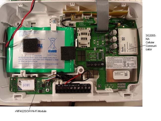
Click to zoom
Application Details
- Equipment Class
- DTS - Digital Transmission System
- Date of Grant
- Dec 18, 2012
- Application Purpose
- Original Equipment
- Date of Application
- Dec 17, 2012
- Equipment Note
- WiFi Module for DSC Impassa Alarm System
- Frequency Range
- 2412.00000000 - 2462.00000000
- Country
- Canada
Documents & Files
Document Text
Text extracted from the exhibit documents filed with the FCC. Open a document above to read the original.
Users Manual
WIFI422SCW MODULE INSTALLATION SHEET Introduction The WIFI422SCW module provides a wireless link from the host security control panel to the C24 Interactive gateway. This manual provides installation and setup information for WiFi422SCW only. Features & Specifications Compatibility This module is compatible with the following SCW control panels: SCW9055-SM-433, SCW9055D-SM-433, SCW9055G-SM-433, SCW9055I-SM-433, SCW9057-SM-433, SCW9057D-SM-433, SCW9057G-SM-433, SCW9057I-SM-433. Installation and Wiring Insert WIFI422SCW module into the SCW905X backplate. Refer to Table 1 below for wiring details. Table 1: WIFI422SCW Module Wiring Connections Figure 1: WIFI422SCW Module Wiring Setup & Programming The WIFI422SCW module receives power from the control panel AUX output and it communicates via the RS-422 interface on the 3G2055-SM-NA or TL2553G-SM-NA communicators. 1. Enter section [851][920]. • The communicator will send a command to initiate Wi-Fi Protected Setup (WPS). • The message “WPS Success” is displayed when setup is complete. PGM Attribute Please refer to the SCW9055/9057 Installation Manual to configure PGM1 to Pulse. The default configuration (5 seconds) is recommended. [920] Initiate Protected Setup Upon entering this section the WIFI422SCW module shall initiate WPS and connect to the nearest Access Point (AP) also performing WPS. The LCD shall display “WPS Enroll- ment in Progress”. • Upon failure of enrollment, the LCD shall display “WPS Enrollment Failure”. • Upon successful of enrollment, the LCD shall display “WPS Enrollment Success”. NOTE: If you exit this section, all Wi-Fi sections are blocked until WPS is either successful or has failed. The longest possible lock out is 1 minute. NOTE: Communicator Option [663] must be 11, configured for Interactive over Gateway. If this section is any other value, Wi-Fi sections are also blocked. [921] WIFI422SCW Module Factory Default Default (99) Enter [00] to perform a factory default, this will disconnect the WiFi422SCW from the Access Point. The installer must perform a WPS with the new Access Point in order to enroll the router. Once the Access Point is disconnected, the default SSID will display “X”. [922] SSID Display Enter section [851][922] to obtain the SSID of the currently enrolled Access Point. The keypad will display the SSID of the network that it is using. If the WiFi422SCW is not connected to any Access Point, the keypad will display “X” to indicate the network connection has not been created. [923] Signal Strength Display Enter section [851][923] to view the Wi-Fi signal strength. Once in this section, the keypad will display the signal strength with respect to the Access Point it is currently using. If the WiFi422SCW is not associated with any Access Point, the Keypad will display “X------” NOTE: This section is available on the display of the control panel only. Table 2: Signal Strength Display Troubleshooting FCC/IC This modular transmitter is labeled with its own FCC ID and IC number. When the mod- ule is installed inside the host device and the FCC ID/IC of the module is not visible the host device shall display the provided label referring to the FCC ID and IC of the enclosed module. This label is shipped together with the module and it is the responsibility of the integrator to apply it to the exterior of the enclosure as indicated below. FCC COMPLIANCE STATEMENT CAUTION: Changes or modifications not expressly approved by DSC could void your authority to use this equipment. This equipment generates and uses radio frequency energy and if not installed and used properly, in strict accor- dance with the manufacturer’s instructions, may cause interference to radio and television reception. It has been type tested and found to comply with the limits for Class B device in accordance with the specifications in Sub- part “B” of Part 15 of FCC Rules, which are designed to provide reasonable protection against such interfer- ence in any residential installation. However, there is no guarantee that interference will not occur in a particular installa- tion. If this equipment does cause interference to television or radio reception, which can be determined by turning the equipment off and on, the user is encouraged to try to correct the interference by one or more of the following measures: • Re-orient the receiving antenna • Relocate the alarm control with respect to the receiver • Move the alarm control away from the receiver • Connect the alarm control into a different outlet so that alarm control and receiver are on different circuits. If necessary, the user should consult the dealer or an experienced radio/television technician for additional sug- gestions. The user may find the following booklet prepared by the FCC helpful: “How to Identify and Resolve Radio/Television Interference Problems”. This booklet is available from the U.S. Government Printing Office, Washington,D.C. 20402, Stock # 004-000-00345-4. This device complies with Part 15 of the FCC Rules and with Industry Canada license exempt RSS standard(s). Operation is subject to the following two conditions: (1) this device may not cause harmful interference, and (2) this device must accept any interference received, including interference that may cause undesired operation. “ “Le présent appareil est conforme aux CNR d'Industrie Canada applicables aux appareils radio exempts de licence. L'exploitation est autorisée aux deux conditions suivantes: (1) l'appareil ne doipas produire de brouil- lage, et (2) l'utilisateur de l'appareil doit accepter tout brouillage radioélectrique subi, même si le brouillage est susceptible d'en compromettre le fonctionnement. • RS-422 interface• Dimensions: 64mm × 24.71 mm • SSID indication (SCW variant)• Indoor range: 32m (120ft) • Signal strength indication• Outdoor range: 95m(300ft) • Reset via PGM• Power consumption: 66mA (max.) / 12V • SW WPS Setup• Humidity: 85%, non-condensing • WPA2 PSK• Wi-Fi Data Rate: 802.11 b/g • UART Se…
Text truncated - open the document above for the full version.
Attestation Statements
Digital Security Controls 3301 Langstaff Road Concord, Ontario Canada L4K 4L2 Tele: 905 760 3000 Toll Free: 888 888 7838 www.dsc.com To Whom It May Concern: Subject: Validity of Test Results from Testing / Certification of the integrated Module WE, Digital Security Controls, a division of Tyco Safety Products Canada Ltd., having a business address at 3301 Langstaff Rd., Concord, ON L4K4L2, Canada: This is to confirm that the results from conducted tests applied to the radio module Roving Networks Inc., model RN-171 with FCC ID: T9J-RN171and IC: 6514A-RN171 which is incorporated in our host equipment DSC, Model WiFi422SCW with FCC ID: F5312WiFi422SCW and IC: 160A-WiFi422SCW and as reported in module test test report: W6M21012-11105-C-1 issued by Worldwide Testing Services (Taiwan) Co., Ltd. on February 8 th , 2011accurately represents the test results under the new conditions when the identified radio module is integrated in the identified host equipment. By integration of the said radio module into the identified host equipment no changes were made to it or by external adaptation circuitry that impacts the validity of the results of the original module’s test reports. Dan Nita Dated: November 07, 2012
Attestation Statements
Digital Security Controls 3301 Langstaff Road Concord, Ontario Canada L4K 4L2 Tele: 905 760 3000 Toll Free: 888 888 7838 www.dsc.com December 14, 2012 To Whom It May Concern Subject: WiFi422SCW WiFi Module for Impass Alarm Control Panle – Operating Channels FCC ID: F5312WiFi422SCW IC: 160A-WiFi422SCW This is to confirm that the Roving Networks WiFi radio module, model RN-171 (FCC ID: T9J-RN171) used in our interface model WiFi422SCW is operating only on channels 1 to 11 (frequency range 2412MHz to 2462MHz) in US and Canada. The operation only on the channels 1-11 is preset on the RN-171 radio module from Roving Networks and our interface, WiFi422SCW, does not have any capability to control or change the operating channels as they have been set in the RN-171 radio module. Should you have additional questions regarding this matter please do not hesitate to contact me directly. Your truly, Dan Nita Approvals Manager Ext. 2706
Cover Letter(s)
Digital Security Controls 3301 Langstaff Road Concord, Ontario Canada L4K 4L2 Tele: 905 760 3000 Toll Free: 888 888 7838 www.dsc.com December 14, 2012 Federal Communications Commission 7435 Oakland Mills Road Columbia, MD 21046-1609 Re: FCC ID: F5312WiFi422SCW – Limited Modular Approval Dear examiner, We the undersigned intent to submit for authorization WiFi422SCW under FCC ID: F5312WiFi422SCW as a limited modular approval as per FCC rule Part 15.212. This device meets the requirements as a modular device stated in public notice DA00-1407 and KDB996369 DR01 v01r03 and summarized below: 1. This modular transmitter has its own RF shielding and will not rely upon the shielding provided by the host into which it is installed in order for all modular transmitter emissions to comply with Part 15 limits, nor will it cause any coupling between the RF circuitry of the module and any wires or circuits in the device into which the module is installed. WiFi422SCW contains the WiFi module from Roving (FCC ID: T9J-RN171) that is shielded. Please see attached pictures. 2. This modular transmitter has buffered input data according the definition of DA00-1407 and complies with Part 15 requirements under conditions of excessive data rates or over-modulation. WiFi422SCW contains the WiFi module from Roving (FCC ID: T9J-RN171) that has buffered input data. 3. The modular transmitter has its own power supply regulation to ensure compliance with Part 15 requirements regardless of the design of the power supplying circuitry in the host device into which the module is installed. WiFi422SCW contains its own regulator U1 (please refer to attached schematic for UA608 Rev. 03). 4. This modular transmitter complies with the antenna requirements of FCC rule Tile 47 Section 15.203 and 15.204(c). The antenna is permanently attached. WiFi422SCW has the antenna soldered to the PCB assembly (UA608 Rev. 03). 5. WiFi422SCW was tested within the host equipment DSC alarm control panel SCW9057 (G)-433. It is intended to be used together with the commercially available DSC alarm control panels family of models: SCW9055(D)(G)(I)-433 and SCW9057(D)(G)(I)-433. The device is provided with power from the host control panel and communicates with a serial interface inside this host control panel. The DSC alarm control panel incorporates another cellular radio transmitter which is modular approved under (FCC ID: F53113G255SM and IC ID IC: 160A-3G255SM). . 6. This modular transmitter will be labeled with its own FCC ID number. In the event that the module is installed inside a host device and the FCC ID of the module is not visible the host device will display a label referring to the FCC ID of the enclosed module. We the grantee will either provide such a label to the integrator or instructions explaining this requirement. A copy of these instructions will be included in this application for equipment authorization. WiFi422SCW has its own FCC ID label (see attached drawing) and it is shipped with an additional label that is applied to the host control on the outside enclosure. Instructions on how to apply the label are provided with the User Manual available for this module. 7. This modular transmitter complies with any specific rule or operating requirements applicable to the transmitter. Adequate instructions, along with the module, will be provided to the integrator to explain any such requirements. A copy of these instructions will be included in this application for equipment authorization. WiFi422SCW has its own User/Instructions manual that is provided to the end user for assistance with the installation and setting of the module. See attached submitted manual. Digital Security Controls 3301 Langstaff Road Concord, Ontario Canada L4K 4L2 Tele: 905 760 3000 Toll Free: 888 888 7838 www.dsc.com 8. This modular transmitter complies with any applicable RF exposure requirements. The EMC laboratory of Cetecom Inc., Milpitas, CA, USA has verified compliance with the applicable RF exposure requirements, please refer to the submitted test reports. Yours truly, Dan Nita DSC, Approvals Manager 905-760-3000
Cover Letter(s)
Digital Security Controls 3301 Langstaff Road Concord, Ontario Canada L4K 4L2 Tele: 905 760 3000 Toll Free: 888 888 7838 www.dsc.com October 15, 2012 Equipment Autorisation Division Federal Communications Commission 7435 Oakland Mills Road Columbia, MD 21046 FCC ID: F5312WiFi422SCW Product Name: WiFi Module for Alarm System, model WiFi422SCW Request for Confidentiality Pursuant to Sections 0.457 and 0.459 of the commissions rules, we hereby request that the following documents be held confidential: Schematics Block diagram Operational Description Parts Lists / Tune-up Information These materials contain trade secrets and proprietary information and are not customarily released to the public. The public disclosure of this information might be harmful to the company and provide unjustified benefits to our competitors. Dated this 15th Day of October 20 12 By: Dan Nita Signature Printed Title: Approvals Manager On behalf of : Digital Security Controls Telephone: 905-760-3000, Ext. 2706
External Photos
Registration number: W6M21012-11105 FCC ID: T9J-RN171 Worldwide Testing Services(Taiwan) Co., Ltd. Page 2 of 22 External Photos Antenna 1 Registration number: W6M21012-11105 FCC ID: T9J-RN171 Worldwide Testing Services(Taiwan) Co., Ltd. Page 3 of 22 Registration number: W6M21012-11105 FCC ID: T9J-RN171 Worldwide Testing Services(Taiwan) Co., Ltd. Page 4 of 22 Registration number: W6M21012-11105 FCC ID: T9J-RN171 Worldwide Testing Services(Taiwan) Co., Ltd. Page 5 of 22 Registration number: W6M21012-11105 FCC ID: T9J-RN171 Worldwide Testing Services(Taiwan) Co., Ltd. Page 6 of 22 Antenna 2 Registration number: W6M21012-11105 FCC ID: T9J-RN171 Worldwide Testing Services(Taiwan) Co., Ltd. Page 7 of 22 Registration number: W6M21012-11105 FCC ID: T9J-RN171 Worldwide Testing Services(Taiwan) Co., Ltd. Page 11 of 22 Registration number: W6M21012-11105 FCC ID: T9J-RN171 Worldwide Testing Services(Taiwan) Co., Ltd. Page 12 of 22 Antenna 4 Registration number: W6M21012-11105 FCC ID: T9J-RN171 Worldwide Testing Services(Taiwan) Co., Ltd. Page 13 of 22 Registration number: W6M21012-11105 FCC ID: T9J-RN171 Worldwide Testing Services(Taiwan) Co., Ltd. Page 15 of 22
ID Label/Location Info
18008804R001 WiFi422SCW FCC/IC Label October 25, 2012 Colour: Pantone Process Black Material: WHITE Durable Semi-gloss Self-adhesive Material (e.g. PL 38 Q, or equivalent) - on a roll Lamination: Top gloss finish lamination (e.g. 1F9, or equivalent) Adhesive: Permanent adhesive backed with protective liner (e.g. 60# Semigloss Tire-III / 40# Liner Code: B37, or equivalent) Cutting: Tolerance +/- 0.010” Dashed line indicates cutting - will not print Square label corners are acceptable NOTES: 1. All items must be RoHS compliant. 2. Markings on label must be PERMANENT. 3. Indelible Ink. 4. Conductive inks may not be used. 5. Non-conductive label adhesive shall be used ONLY. Digital Security Controls 3301 Langstaff Road Concord, Ontario Canada L4K 4L2 Tele: 905 760 3000 Toll Free: 888 888 7838 Fax: 905-760-3020 The label is to be located on the top of the unit (PCB) as shown above in actual size Label 18008804 Label shown 300% actual size 16 mm 10 mm M/N: WiFi422SCW FCC ID:F5312WiFi422SCW IC:160A-WiFi422SCW MADE IN CANADA 18008804R001 M/N: WiFi422SCW FCC ID:F5312WiFi422SCW IC:160A-WiFi422SCW MADE IN CANADA 18008804R001
Internal Photos
Registration number: W6M21012-11105 FCC ID: T9J-RN171 Worldwide Testing Services(Taiwan) Co., Ltd. Page 16 of 22 Internal Photos Registration number: W6M21012-11105 FCC ID: T9J-RN171 Worldwide Testing Services(Taiwan) Co., Ltd. Page 17 of 22
RF Exposure Info
RF Exposure Evaluation Report FOR: Manufacturer: Digital Security Controls, a division of Tyco Safety Products Canada Ltd. Model Name: WiFi422SCW Product Description: WiFi Module for DSC Impassa Alarm System FCC ID: F5312WiFi422SCW IC ID: 160A-WiFi422SCW References: 1. FCC OET Bulletin 65 Supplement 2. FCC CFR Part 1 (1.1307 &1.1310), Part 2 (2.1091) 3. RSS-102- Radio Frequency Exposure Compliance of Radiocommunication Apparatus Issue 4 March 2010, Ch, 2.5 and Ch. 4 Test Report #: EMC_ TYCOS-045-12001_MPE FCC ID: F5312WiFi422SCW Date of Report : 2012-12-18 IC ID: 160A-WiFi422SCW May 15 2012. Rev 2.0 Page 2 of 9 1 Administrative Data 1.1 Identification of the Testing Laboratory Issuing the Test Report Company Name: CETECOM Inc. Department: Compliance Address: 411 Dixon Landing Road Milpitas, CA 95035 U.S.A. Telephone: +1 (408) 586 6200 Fax: +1 (408) 586 6299 Test Lab Manager: Sajay Jose Test Engineer: Zack Gray 1.2 Identification of the Client Applicant’s Name: Digital Security Controls, a division of Tyco Safety Products Canada Ltd. Street Address: 3301 Langstaff Road City/Zip Code Concord, ON L4K 4L2 Country CA Contact Person: Dan Nita Phone No. (905) 760-3000 Ext. 2706 1.3 Identification of the Manufacturer Same as client. Test Report #: EMC_ TYCOS-045-12001_MPE FCC ID: F5312WiFi422SCW Date of Report : 2012-12-18 IC ID: 160A-WiFi422SCW May 15 2012. Rev 2.0 Page 3 of 9 2 Equipment under Test (EUT) 2.1 Specification of the Equipment under Test Model No: WiFi422SCW HW Version: UA608 Rev. 03 SW Version: Ver 1.0 EUT S/N Tested: 8007D0 FCC-ID: F5312WiFi422SCW IC-ID: 160A-WiFi422SCW Product Description: WiFi Module for DSC Impassa Alarm System Frequency Range / number of channels: 2412 MHz- 2462 MHz / 11 Type(s) of Modulation: 802.11b: DSSS 802.11g: OFDM Modes of Operation: 802.11b / 802.11g Antenna Type and Gain: Ceramic Antenna Manufacturer specified Peak Gain: 0.5 dBi for all channels Co-located Transmitters/ Antennas? Yes: with FCC ID: F53113G255SM (IC ID: 160A- 3G255SM) No Power supply: Internal battery Powered: 10 V min/ 12 V nom/12.5 V max Additionally, powered by 110V AC/DC adapter Operating temperature range: -10 o C – 55 o C Prototype / Production unit: Prototype Device Category: Fixed Installation Mobile Portable Exposure Category: Occupational/ Controlled General Population/ Uncontrolled Test Report #: EMC_ TYCOS-045-12001_MPE FCC ID: F5312WiFi422SCW Date of Report : 2012-12-18 IC ID: 160A-WiFi422SCW May 15 2012. Rev 2.0 Page 4 of 9 3 Assessment This report serves as the Technical Information regarding RF Exposure evaluation of the below identified device according to the rules as stipulated in the documents listed under References above. The device meets the RF exposure limits, or - for some of it's radio functions / bands - the conditions for exemption from routine evaluation as defined in the referenced FCC and IC rule parts. Company Description Model # Digital Security Controls, a division of Tyco Safety Products Canada Ltd. WiFi Module for DSC Impassa Alarm System WiFi422SCW 2012-12-18 Compliance Zack Gray (Test Engineer) Date Section Name Signature Test Report #: EMC_ TYCOS-045-12001_MPE FCC ID: F5312WiFi422SCW Date of Report : 2012-12-18 IC ID: 160A-WiFi422SCW May 15 2012. Rev 2.0 Page 5 of 9 4 RF Exposure Evaluation Requirements 4.1 FCC: Calculations can be made to predict RF field strength and power density levels around typical RF sources using the general equations (3) and (4) on page 19 of the following FCC document: “OET Bulletin 65, Edition 97-01 - Evaluating Compliance with FCC Guidelines for Human Exposure to Radio frequency Electromagnetic Fields”. The table below is excerpted from Table 1B of 47 CFR 1.1310 titled Limits for Maximum Permissible Exposure (MPE), Limits for General Population/Uncontrolled Exposure: Fre que ncy Range (MHz) Powe r de ns ity (mW/cm 2 ) Ave raging time (minute s ) 300 – 1500 f (MHz) /1500 30 1500 – 100.000 1.0 30 Using the equation from page 19 of OET Bulletin 65, Edition 97-01: 2 4R PG S where: S = power density (in appropriate units, e.g. mW/cm 2 ) P = power input to the antenna (in appropriate units, e.g., mW) G = power gain of the antenna in the direction of interest relative to an isotropic radiator R = distance to the center of radiation of the antenna (appropriate units, e.g., cm) Additionally, according to § 2.1091: The limit for <1.5 GHz mobile operations where no routine evaluation is required is: 1.5W ERP The limit for >1.5 GHz mobile operations where no routine evaluation is required is: 3W ERP 4.2 IC: RSS-102 Se ction 2.5.2 RF exposure evaluation is required if the separation distance between the user and the device's radiating element is greater than 20 cm, except when the device operates as follows: below 1.5 GHz and the maximum EIRP of the device is equal to or less than 2.5 W; at or above 1.5 GHz and the maximum EIRP of the device is equal to or less than 5 W. RSS-102 4.2: RF Field s trength limits for de vices used by the Ge neral Public (Uncontrolled Environme nt): Power density 300MHz- 1500 MHz= f/150 W/m 2 1500 MHz- 1500000 MHz= 10 W/m 2 Test Report #: EMC_ TYCOS-045-12001_MPE FCC ID: F5312WiFi422SCW Date of Report : 2012-12-18 IC ID: 160A-WiFi422SCW May 15 2012. Rev 2.0 Page 6 of 9 5 Measurement procedure: 5.1 Radiated power Calculation- ERP/EIRP- 1. Connect the equipment as shown in the above diagram. 2. Adjust the settings of the EUT to set to transmit at a specific mode. 3. Measure conducted power using the power meter or the Spectrum Analyzer. 4. ERP/EIRP is calculated by adding the antenna gain to the measured conducted power. EIRP= Measured conducted power+ Antenna Gain (dBi) (Antenna gain based on measurement or data from the antenna manufacturer.) ERP= EIRP- 2.14 5.2 Measurement Equipment information: In strument/Ancillary Mode l Man u facturer S e rial No. C al Date C al In te rval Radio Communication Tester CMU 200 Rohde & Schwarz 101821 May 2011 2 Years EMI Receiver/Analyzer ESU 40 Ro…
Text truncated - open the document above for the full version.
Test Report
FCC : Accredited IC recognized # 3462B CETECOM Inc. 411 Dixon Landing Road Milpit as, CA 95035 U.S.A. P hone: + 1 (408) 586 6200 Fax: + 1 (408) 586 6299 E-mail: info@ cetecomusa.com http://www.cetecom.com CETECOM Inc. is a Delaware Corporation with Corporation number: 2905571 V3.0 2010-10-30 © Copyright by CETECOM FCC/IC Test Report FOR Manufacturer: Digital Security Controls, a division of Tyco Safety Products Canada Ltd. Model Number: WiFi422SCW Product Description: WiFi Module for DSC Impassa Alarm System FCC ID: F5312WiFi422SCW IC ID: 160A-WiFi422SCW 47 CFR Part 15.247 for DTS Systems IC RSS-210 Issue 8 TEST REPORT #: EMC_TYCOS-045-12001_DTS DATE: 2012-12-18 Te s t Re port #: EMC_TYCOS-045-12001_DTS FCC ID: F5312WiFi422SCW Date of Re port : 2012-12-18 IC ID: 160A-WiFi422SCW Page 2 of 41 TABLE OF CONTENTS 1 Assessment..........................................................................................................................................4 2 Administrative Data ............................................................................................................................5 2.1 Identification of the Testing Laboratory Issuing the Test Report ......................................................... 5 2.2 Identification of the Client................................................................................................................ 5 2.3 Identification of the Manufacturer .................................................................................................... 5 3 Equipment under Test (EUT)..............................................................................................................6 3.1 Specification of the Equipment under Test ........................................................................................ 6 3.2 Identification of the Equipment Under Test (EUT) ............................................................................ 7 3.3 Identification of Accessory Equipment ............................................................................................. 7 3.4 Environmental conditions during Test: ............................................................................................... 7 3.5 Dates of Testing: ............................................................................................................................ 7 3.6 Test modes of operation: ................................................................................................................. 7 4 Subject of Investigation ......................................................................................................................8 5 Summary of Measurement Results ...................................................................................................9 6 Measurements ..................................................................................................................................10 6.1 Radiated Measurement Procedure ................................................................................................. 10 6.2 Measurement Method: .................................................................................................................. 10 6.3 Radiated Measurement Procedure ................................................................................................. 10 6.4 Sample Calculations for Radiated Measurements ............................................................................ 12 6.5 Conducted Measurement Procedure .............................................................................................. 13 6.6 Maximum Peak Conducted Output Power ...................................................................................... 14 6.6.1 Limits: .....................................................................................................................................14 6.6.2 Test Conditions: ......................................................................................................................14 6.6.3 Test Procedure:.......................................................................................................................14 6.6.4 Test Result:..............................................................................................................................15 6.6.5 Test Data/plots: .......................................................................................................................16 6.7 Unwanted Emissions into Restricted Frequency Bands- Radiated..................................................... 18 6.7.1 Limits: .....................................................................................................................................18 6.7.2 Test Conditions: ......................................................................................................................20 6.7.3 Test Procedure:.......................................................................................................................20 6.7.4 Test Data/plots: .......................................................................................................................21 6.8 Transmitter Spurious Emissions- Radiated ...................................................................................... 25 6.8.1 Limits: .....................................................................................................................................25 6.8.2 Test Conditions: ......................................................................................................................25 6.8.3 Test Result:..............................................................................................................................25 6.8.4 Test data/ plots:.......................................................................................................................26 6.9 AC Power Line Conducted Emissions ...........................................…
Text truncated - open the document above for the full version.
Test Report
of Applicant: ROVING NETWORKS, INC. Address: 809 UNIVERSITY AVENUE. LOS GATOS, CA 95032 U.S.A. Tested and Prepared by Worldwide Testing Services (Taiwan) Co., Ltd. FCC Registration No.: 930600 Industry Canada filed test laboratory Reg. No. IC 5679A-1 A2LA Accredited No.: 2732.01 Report No.: W6M21012-11105-C-1 6F, NO. 58, LANE 188, RUEY-KUANG RD., NEIHU TAIPEI 114, TAIWAN, R.O.C. TEL: 886-2-66068877 FAX: 886-2-66068879 E-mail: [email protected] FCC PART 15 SUBPART C TEST REPORT for WIFLY Model No.: RN-171 FCC ID: T9J-RN171 Registration number: W6M21012-11105-C-1 FCC ID: T9J-RN171 Worldwide Testing Services(Taiwan) Co., Ltd. Page 1 of 44 TABLE OF CONTENTS 1 GENERAL INFORMATION ..........................................................................................................2 1.1 N OTES..........................................................................................................................................2 1.2 T ESTING LABORATORY................................................................................................................3 1.2.1 Location ..............................................................................................................................3 1.2.2 Details of accreditation status ............................................................................................3 1.3 DETAILS OF APPROVAL HOLDER...................................................................................................3 1.4 A PPLICATION DETAILS.................................................................................................................4 1.5 G ENERAL INFORMATION OF TEST ITEM........................................................................................4 1.6 TEST STANDARDS.........................................................................................................................5 2 TECHNICAL TEST .........................................................................................................................6 2.1 SUMMARY OF TEST RESULTS........................................................................................................6 2.2 T …
Text truncated - open the document above for the full version.
Contact Information
Applicant
Dan Nita(Approvals Manager)
Test Firm
CETECOM Inc.Meinolf Glunz
[email protected]408-586-6301
Technical Specifications
| # | Rule Parts | Frequency Range | Power Output |
|---|---|---|---|
| 1 | 15C | 2.41 GHz - 2.46 GHz | 32.00 mW |
Other Applications from Tyco Safety Products Canada Ltd.

F53252RFLOCK
Jun 05, 2026IQ Lock-PGP, IQ Lock Touch-PGP
Equipment Class
DTS - Digital Transmission System
F5325PGPDC9
Apr 27, 2026PowerG wireless transceiver module
Equipment Class
DSS - Part 15 Spread Spectrum Transmitter
F5325LC203424
Dec 17, 2025Dual Technology Motion Sensor
Equipment Class
FDS - Part 15 Field Disturbance SensorF5324PGPIO9
Dec 04, 2024Wireless Input / Output (I/O) w/wo contact
Equipment Class
DSS - Part 15 Spread Spectrum Transmitter
F5323PGP9934P
Jan 16, 2024Wireless Motion detector with integrated camera
Equipment Class
DSS - Part 15 Spread Spectrum Transmitter