F5312WS4928Wireless Holdup Switch
Tyco Safety Products Canada Ltd.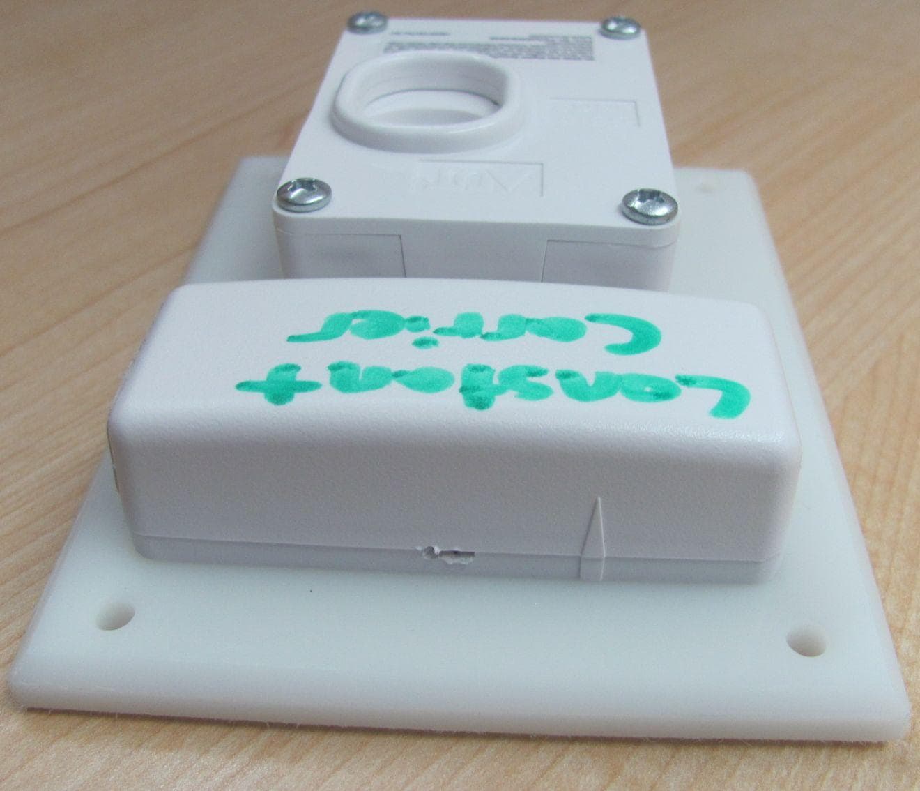
Click to zoom
Application Details
- Equipment Class
- DSC - Part 15 Security/Remote Control Transmitter
- Date of Grant
- Apr 22, 2012
- Application Purpose
- Original Equipment
- Date of Application
- Apr 22, 2012
- Equipment Note
- Wireless Holdup Switch
- Frequency Range
- 433.92000000 - 433.92000000
- Country
- Canada
Documents & Files
Document Text
Text extracted from the exhibit documents filed with the FCC. Open a document above to read the original.
Users Manual
WS4928 Holdup Switch Installation Instructions - For Service Persons Only These instructions shall be used with the Installation Manual of the DSC wireless receiver and control panel with which this device is intended to be used. The WS4928 wireless holdup switch is intended for installation under a counter, desktop, switchboard or other concealed location. Specifications Out of the Box • 1 WS4928 module • 1 reset tool • 4 mounting screws Powering the WS4928 The WS4928 comes with the battery pre-installed. To activate, hold the WS4928 firmly in one hand and pull the plastic tab in the direction indicated. Locate Transmitter Select the location where the WS4928 is to be mounted. NOTE: RF signals can be affected by metal objects, including metal doors or large mirrors. Such locations should be avoided, they can interfere with proper operation. Enrolling, Programming and Placement Enroll the WS4928 by programming the 6-digit serial number (located on the WS4928) into the receiver. Once the WS4928 is enrolled, you must perform a Module Placement test to ensure the location you have chosen is suitable. The following outlines the basic steps for programming and enrolling this device on PowerSeries receivers. For additional options or for other receivers please refer to the specific receiver installation manuals. Step 1 – Program Electronic Serial Number (ESN) Section [804], subsections [01] – [64] [01] Zone 1 ... [64] Zone 64 Enter the 6 digit ESN located on the WS4928 into the next available zone slot. Step 2 – Program Zone Definition Section [001] – [004] Define corresponding zone with appropriate zone type [i.e., Holdup (12)]. Step 3 – Enable Wireless Zone Attribute Section [101] – [164] Turn Option [8] ON (wireless zone attribute) in corresponding zone attribute section. All wireless devices must be tested for good signal strength from where they are positioned. Step 4 – Device Placement Test Section [904], subsections [01] – [64] Activate the switch. The panel will indicate the test result through the siren (and also through the keypad): 1 bell squawk/beep on LCD keypad/LED 1 on LED keypad) indicates GOOD placement 3 bell squawks/beeps on LCD keypad/LED 3 on LED keypad) indicates BAD placement If the transmitter tests BAD, move the transmitter and repeat the Placement Test. Mounting the Device Secure the holdup switch to the mounting surface using the 4 mounting screws provided. NOTE: The WS4928 may be mounted horizontally or vertically. In horizontal installations, position the unit so that the finger-operated slide is acti- vated by pulling toward the user. In vertical installations, position the unit so that the finger-operated slide is activated by pulling downward by the user. Operation Activation - The WS4928 holdup switch is activated by placing a finger in the access hole and pulling the slide toward the user (downward in vertical mount installations). The alarm activation will be indicated locally at the device by the red tab on the unit. The device will remain latched in the alarm state until a manual reset is performed. Restoral - To restore the device, insert the reset tool into the two rectangular slots next to the alarm indicating tab. Ensure the flat (unbevelled) side is facing the red tab (see Figure A). Testing 1. Notify the central station prior to testing the switch. 2. Activate the switch. 3. Reset the switch. 4. Verify receipt of the alarm and restoral signal at the central station and provide notification that the test is completed. Tamper Switch & Wall Tamper The WS4928 comes equipped with case tamper detection. If the case is removed, the WS4928 will report a zone tamper to the control panel. For added security the WS4928 was designed to provide wall tamper monitoring as well. When using the wall tamper please do not install the device on surfaces made of soft materials. NOTE: A tamper switch is required for UL Listed commercial burglary/holdup installations. Replacing the Battery To replace the battery, insert a flathead screwdriver into either side of the transmitter unit and carefully twist to separate the top and bottom plastic (see Figure B). Once separated, the battery will be visible (please see Figure C). Remove the old battery and install new battery. Ensure correct polarity is observed. Dispose of used battery promptly. CAUTION: The battery used in this device may present a fire or chemical burn hazard if mistreated. Do not recharge, disassemble, heat above 100C (212F) or dispose of in fire. Replace battery with one 3V lithium bat- tery, Panasonic CR2 or Duracell CR2 only. Use of another battery may present a risk of fire or explosion. Dispose of the used batteries as per local regulations. Keep away from children. NOTE: Model WS4928 is UL listed for commercial burglary/holdup applications in accordance with the following standards: UL636, UL1610. NOTE: Test unit at least once yearly. Dimensions:95mm × 121mm × 38mm (3¾”x 4¾” x 1½”) Operating Temperature:UL/ULC: 0 o C to 49 o C (32 o F to 120 o F) Operating Humidity:85% RH Operating Frequency:433 MHz Battery:Duracell/Panasonic CR2 Lithium (2.2V low battery indication threshold) Battery Life:5-8 years * Compatible Receivers:RF5132-433 with DSC control panel models PC1616, PC1832, PC1864 * Not tested by UL/ULC. Alarm State Indicator Holdup Switch Reset Tool Wireless Transmitter Figure A To remove cover, insert screwdriver here and gently twist. Figure B Tamper Switch BATTERY External Contact Terminals Figure C FCC Compliance Statement CAUTION: Changes or modifications not expressly approved by DSC could void your authority to use this equipment. This equipment generates and uses radio frequency energy and if not installed and used properly, in strict accordance with the manufacturer’s instructions, may cause interference to radio and television reception. It has been type tested and found to comply with the limits for Class B device in accordance with the specifications in Subpart “B” of Part 15 of FCC Rules…
Text truncated - open the document above for the full version.
Cover Letter(s)
Digital Security Controls 3301 Langstaff Road Concord, Ontario Canada L4K 4L2 Tele: 905 760 3000 Toll Free: 888 888 7838 www.dsc.com April 20, 2012 Nemko Canada Inc 303 River Road Ottawa, Ontario, Canada K1V 1H2 Attn: Director of Certification Authority to Act as Agent On our behalf, I appoint Nemko Canada Inc., 303 River Road, Ottawa, Ontario, Canada K1V 1H2 to act as our agent in the preparation of this application for equipment certification. I certify that submitted documents properly describe the device or system for which equipment certification is sought. I also certify that each unit manufactured, imported or marketed, as defined in the Federal Communications Commission’s regulations will have affixed to it a label identical to that submitted for approval with this application. For instances where our authorized agent signs the application for certification on our behalf, I acknowledge that all responsibility for complying with the terms and conditions for certification, as specified by Nemko Canada Inc, still resides with Digital Security Controls, 3301 Langstaff Road, Concord, Ontario Canada L4K 4L2. Dated this 20th Day of April 20 12 Agency agreement expiration date: April 19, 2013 By: Dan Nita Signature Printed Title: Approvals Manager On behalf of : Digital Security Controls Telephone: 905-760-3000, Ext. 2706
Cover Letter(s)
Digital Security Controls 3301 Langstaff Road Concord, Ontario Canada L4K 4L2 Tele: 905 760 3000 Toll Free: 888 888 7838 www.dsc.com April 20, 2012 Equipment Authorisation Division Federal Communications Commission 7435 Oakland Mills Road Columbia, MD 21046 FCC ID: F5312WS4928 Product Name: DSC Wireless Holdup Switch Model: WS4928 Request for Confidentiality Pursuant to Sections 0.457 and 0.459 of the commissions rules, we hereby request that the following documents be held confidential: Schematics Parts List Block diagram Operational description These materials contain trade secrets and proprietary information and are not customarily released to the public. The public disclosure of this information might be harmful to the company and provide unjustified benefits to our competitors. Dated this 20 th Day of April 20 12 By: Dan Nita Signature Printed Title: Approval Manager On behalf of : Digital Security Controls Telephone: 905-760-3000, Ext. 2706
External Photos
External EUT photos Front view Side view Side view Rear view Bottom view
ID Label/Location Info
18008728R001 WS4928 FCC/IC/UL Label April 5, 2012 Label shown 200% of actual size 35 mm 12.7 mm Digital Security Controls 3301 Langstaff Road Concord, Ontario Canada L4K 4L2 Tele: 905 760 3000 Toll Free: 888 888 7838 Fax: 905-760-3020 Colour: Pantone Process Black Material: WHITE UL approved self-adhesive Mylar type material - on a roll Lamination: Top gloss finish lamination (e.g. 1F9, or equivalent) Adhesive: Permanent adhesive backed with protective liner (e.g. 60# Semigloss Tire-III / 40# Liner Code: B37, or equivalent) Cutting: Tolerance +/- 0.010” Dashed line indicates cutting - will not print NOTES: 1. All UL and ULC Labels shall be printed on UL approved material. The first time the label is ordered, the artwork must be sent to UL Label Center [email: [email protected], fax: (847)509-6201] for approval. 2. All UL and ULC Labels shall be printed by a UL Listed printing facility. NOTES: 1. All items must be RoHS compliant. 2. Markings on label must be PERMANENT. 3. Indelible Ink. 4. Conductive inks may not be used. Top of the unit showing placement of label (Actual size) Label P/N 18008728 COM BURG HOLDUP SWITCH Model: WS4928 FCC ID: F5312WS4928 IC:160A-WS4928 MADE IN CANADA DIGITAL SECURITY CONTROLS, TORONTO, CANADA 18008728R001 EQUIPMENT 89SL COM BURG HOLDUP SWITCH Model: WS4928 FCC ID: F5312WS4928 IC:160A-WS4928 MADE IN CANADA DIGITAL SECURITY CONTROLS, TORONTO, CANADA 18008728R001 EQUIPMENT 89SL
Internal Photos
Internal EUT photos
Test Report
FCC 15.231.docx - Date: April 16-2012 www.nemko.com Compliance test report ID 205573-1TRFWL Date of issue April 23, 2012 Title 47-Telecommunication Chapter I - Federal Communications Commission Subchapter A - General Part 15 - Radio Frequency Devices Subpart C - Intentional Radiators §15.231- Periodic operation in the band 40.66–40.70 MHz and above 70 MHz Applicant Digital Security Controls, a Division of Tyco Safety Products Canada Ltd. Product WS4928 Model WS4928 FCC ID F5312WS4928 Nemko Canada Inc., a testing laboratory, is accredited by the Standards Council of Canada. The tests included in this report are within the scope of this accreditation SCC Accredited LAB LAB Accrédité CCN TM w w w . n e m k o . c o m Report reference ID: 205573-1TRFWL Page 2 of 22 Test location Nemko Canada Inc. 303 River Road Ottawa, ON, K1V 1H2 Canada Telephone +1 613 737 9680 Facsimile +1 613 737 9691 Toll free +1 800 563 6336 Website www.nemko.com Tested by David Duchesne, Senior EMC/Wireless Specialist Reviewed by April 23, 2012 Andrey Adelberg, Senior EMC/Wireless Specialist Date Limits of responsibility Note that the results contained in this report relate only to the items tested and were obtained in the period between the date of initial receipt of samples and the date of issue of the report. This test report has been completed in accordance with the requirements of ISO/IEC 17025. All results contain in this report are within Nemko Canada’s ISO/IEC 17025 accreditation. Copyright notification Nemko Canada Inc. authorizes the applicant to reproduce this report provided it is reproduced in its entirety and for use by the company’s employees only. Any use which a third party makes of this report, or any reliance on or decisions to be made based on it, are the responsibility of such third parties. Nemko Canada Inc. accepts no responsibility for damages, if any, suffered by any third party as a result of decisions made or actions based on this report. © Nemko Canada Inc. w w w . n e m k o . c o m Report reference ID: 205573-1TRFWL Page 3 of 22 Table of Contents Table of Contents .......................................................................................................................................................................................... 3 Section 1 Report summary .................................................................................................................................................................... 4 1.1 Test specifications ............................................................................................................................................................................ 4 1.2 Statement of compliance ................................................................................................................................................................... 4 1.3 Exclusions......................................................................................................................................................................................... 4 1.4 Test report revision history ................................................................................................................................................................ 4 Section 2 Summary of test results ........................................................................................................................................................ 5 2.1 Results .............................................................................................................................................................................................. 5 Section 3 Equipment under test (EUT) details ..................................................................................................................................... 6 3.1 Applicant ........................................................................................................................................................................................... 6 3.2 Sample information ........................................................................................................................................................................... 6 3.3 EUT information ................................................................................................................................................................................ 6 3.4 Technical information ........................................................................................................................................................................ 7 3.5 EUT exercise and monitoring details ................................................................................................................................................. 7 3.6 EUT setup diagram ........................................................................................................................................................................... 7 Section 4 Engineering considerations ................................................................................................................................................. 8 4.1 Modifications incorporated in the EUT ............................................................................................................................................... 8 4.2 Technical judgment ........................................................................................................................................................................... 8 4.3 Deviations from laboratory tests procedures ..................................................................................................................................... 8 Section 5 Test conditions ...................................................................................................................................................................... 9 5.1 Atmospheric condition…
Text truncated - open the document above for the full version.
Test Setup Photos
Setup photos Radiated emissions setup Radiated emissions setup
Contact Information
Applicant
Dan Nita(Approvals Manager)
Technical Contact
Non-Technical Contact
Digital Security ControlGavin Surath
[email protected]905-760-3000
Test Firm
Nemko Canada IncStuart Beck
Technical Specifications
| # | Rule Parts | Frequency Range | Power Output |
|---|---|---|---|
| 1 | 15.231 | 433.92 MHz - 433.92 MHz | - |
Other Applications from Tyco Safety Products Canada Ltd.

F53252RFLOCK
Jun 05, 2026IQ Lock-PGP, IQ Lock Touch-PGP
Equipment Class
DTS - Digital Transmission System
F5325PGPDC9
Apr 27, 2026PowerG wireless transceiver module
Equipment Class
DSS - Part 15 Spread Spectrum Transmitter
F5325LC203424
Dec 17, 2025Dual Technology Motion Sensor
Equipment Class
FDS - Part 15 Field Disturbance SensorF5324PGPIO9
Dec 04, 2024Wireless Input / Output (I/O) w/wo contact
Equipment Class
DSS - Part 15 Spread Spectrum Transmitter
F5323PGP9934P
Jan 16, 2024Wireless Motion detector with integrated camera
Equipment Class
DSS - Part 15 Spread Spectrum Transmitter