F5321PG9350SLPowerG beam detector with 350ft range
Tyco Safety Products Canada Ltd.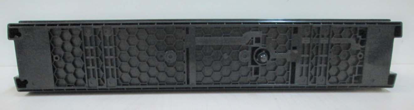
Click to zoom
Application Details
- Equipment Class
- DSS - Part 15 Spread Spectrum Transmitter
- Date of Grant
- Jul 07, 2021
- Application Purpose
- Original Equipment
- Date of Application
- Jul 06, 2021
- Equipment Note
- PowerG beam detector with 350ft range
- Frequency Range
- 912.75000000 - 919.10600000
- Country
- Canada
Documents & Files
Document Text
Text extracted from the exhibit documents filed with the FCC. Open a document above to read the original.
Users Manual
User manual PG9350SL Wireless photoelectric beam detector Detector features • PowerG wireless photoelectric beam detector • Battery life for transmitter is approximately four years, battery life for receiver is approximately five years when using LSH20 (3.6V, 13Ah) batteries manufactured by SAFT • Battery saving function • Intermittent output function • Quad high-power beams • Smart design with slim body • Vivid interior colour for optical alignment • IP65 waterproof structure • 4-channel beam frequency selector • Viewfinder with 2X magnification • Beam interruption adjustment function • D.Q. circuit (environmental disqualification) • Tamper function • LED indicator for an easy alignment • Outdoor detection range of 350 ft Introduction The PG9350SL is a PowerG wireless photoelectric beam detector that provides protection for outdoor perimeters. Warning: Failure to follow the instructions provided with this device or improper handling may cause death or serious injury. Caution: Failure to follow the instructions provided with this device or improper handling may cause injury and/or property damage. Safety information Warnings • Do not use the product for purposes other than the detection of moving objects such as people and vehicles. • Do not use the product to activate a shutter, etc., which may cause an accident. • Do not touch the unit base or power terminals of the product with wet hands. It may cause electric shock. • Do not touch when the product is wet. It may cause electric shock. • Never attempt to disassemble or repair the product. It may cause fire or damage to the devices. • Do not use batteries that have different levels of power remaining, that is, new and used batteries. Not observing these guidelines may result in an explosion, leakage of electrolyte, emission of toxic gases, or other outcomes that may be harmful to people and property. • When handling batteries, do not recharge, short circuit, crush, disassemble, exceed heat above 100°C (212°F), incinerate, or expose contents to water. Do not solder directly to the cell. Not observing these guidelines may result in fire, explosion, or severe burn hazard. Cautions • Do not solder directly to the cell. • Do not pour water over the product with a bucket, hose, or similar. The water may enter, which may cause damage to the devices. • Clean and check the product periodically for safe use. If any problem is found, do not attempt to use the product as it is and have the product repaired by a professional engineer or electrician. Installation advice A Do not install the unit on an unstable surface B Do not install the pole in location where it is not stable. C Do not install the unit near trees or other objects that may block the beam. D The pole size should be 34 - 48 mm (1.34" - 1.89"). E Do not install the receiver in a location that is exposed to direct sunlight. F Install the unit at a height where an object can be detected without fail G Install the unit at least 1 m (3.3 ft.) away from a wall or fence that is parallel to the beam. H Do not install the unit where the infrared beam from a different model can reach the receiver Caution Install the chassis, waterproof packing, and back box together. Not doing this may compromise IP rate of this product. Box contents Transmitter and receiver modules Installation Manual Hardware Pack Parts identification Accessories Ordering detector batteries Specified batteries: Four LSH20 batteries manufactured by SAFT, two for the transmitter and two for the transceiver. For information about batteries, visit the following website and contact your local SAFT sales representative. See http://www.saftbatteries.com/battery-search/ls-lsh/. Enrolment The device is compatible with the following panels: • PowerSeries NEO (v1.37 and higher) • PowerSeries Pro (v1.31 and higher) • IQ2 (v2.6 and higher) • IQ3 (v3.0 and higher) • IQ4 (v4.0 and higher) • PowerSeries NEO2 / Lucy Hybrid v1.0 The device transmitter and receiver enrol separately onto the control panel. The modules can enrol onto the panel in any order. Enrolling the device The device begins the enrolment process when the OPTEX RF module is powered on. The OPTEX RF module is a card in the detector. 1. Install batteries in the detector. 2. Turn the RF module power switch located on the interface board to the ON position. Refer to the control panel installation manual for the complete set of enrolment instructions and testing procedures. The enrolment procedure should begin automatically if the panel is already in enrolment mode. If the automatic enrolment procedure fails, refer to the control panel instructions and attempt manual enrolment of the device. Installation Separating the unit 1. Loosen the cover lock screw with a screwdriver. 2. Place a coin in the recess and twist slightly to remove the cover. 3. Pull the cover from the back of the unit. 4. To remove the main unit from the chassis, turn the optical unit 90° and remove the screws from both sides. 5. Pull the upper part of the main unit forward and up to remove it. Caution: Do not place the main unit where it is exposed to direct sunlight. Doing so may cause damage to the product. 6. Remove the chassis from the back box. Note: The screws to secure the back box cannot be removed from the chassis. Caution: When the waterproof packing is detached, attach it to the back of the chassis before mounting. Not doing so may compromise the IP rate of this product. Notes: Avoid installing the transmitter and receiver facing each other through the corner of the cover. While doing this installation, the maximum detection range must be half of the original detection range to compensate the attenuation of beam by the corner of the cover. Mounting on a wall 1. Using a screwdriver or similar tool, break the six knockouts in the back box. Note: The knockout positions are marked WALL. 2. Mount the back box to the wall. If two detectors are installed, the distance between the upper and lower detector sho…
Text truncated - open the document above for the full version.
Cover Letter(s)
Tyco Safety Products Canada Ltd. 3301 Langstaff Road Concord, Ontario, Canada L4K 4L2 Tele: 1-647-480-0200 https://www.tycosafetyproducts.com May 3, 2021 Telefication B.V. Attn: Dept. FCC TCB Wilmersdorf 50 7327 AC Apeldoorn The Netherlands Subject: Application for certification of a PowerG beam detector with 350ft range, FCC ID:F5321PG9350SL Dear Gentlemen, Please find attached our application for certification of the PowerG beam detector with 350ft range, FCC ID:F5321PG9350SL, prepared in accordance with FCC Rules, parts 2 and 15, section 15.247(FHSS). The product testing and this application for certification were performed by Hermon Laboratories, which is recognized and accredited by FCC, Test Firm Registration Number is 927748, Designation Number is IL1001. Hermon Labs responsible person is Mr. Michael Nikishin, tel: +972 4626 8440, fax:+972 4628 8277, e-mail: [email protected]. We hope this application satisfies your requirements. Please send an invoice to Hermon Labs. Dan Nita, Approvals Manager Tyco Safety Products Canada Ltd.
Cover Letter(s)
Tyco Safety Products Canada Ltd. 3301 Langstaff Road Concord, Ontario, Canada L4K 4L2 Tele: 1-647-480-0200 https://www.tycosafetyproducts.com Declaration of Authorization We Name: Tyco Safety Products Canada Ltd. Address: 3301 Langstaff Road City: Concord L4K 4L2 Country: Ontario, Canada Declare that: Name Representative of agent: ............. (1) Agent Company name: Hermon Laboratories Ltd. Address: Harakevet Industrial Zone City: Binyamina 30500 Country Israel is authorized to apply for Certification of the following product(s): Product description: PowerG beam detector with 350ft range Type designation: PG9350SL Trademark: DSC/Tyco Validity/ expiry date: May 3, 2022 on our behalf. Date: May 3, 2021 City: Concord Name: Dan Nita Function: Approvals Manager Signature: Notes: (1): Required for FCC application (2): For FCC it must be the Grantee Code “owner” or the authorized agent
Cover Letter(s)
FCC, Request for non-disclosure Date: 21-Nov-2018 RF_501, Issue 8 Page 1 of 1 Company Name: Tyco Safety Products Canada Ltd. Address : 3301 Langstaff Road, City: Concord L4K 4L2, Country: Ontario, Canada To: Telefication B.V., Dept. FCC TCB Wilmersdorf 50 7327 AC Apeldoorn The Netherlands Subject: Request for confidentiality FCC ID:F5321PG9350SL Reference number: 31389 Dear FCC TCB, 1. Long-Term Confidentiality Pursuant to 47 CFR Section 0.459(a) & (b), we hereby requests non-disclosure and confidential treatment of the following materials submitted in support of FCC certification application: Bill(s) of Material Block Diagrams Operational Description Schematic Diagrams Tune-up Procedure Above materials contain secrets, proprietary and technical information, which would customarily be guarded from competitors under 47 CFR, section 0.457(d)(2). Disclosure or publication or any portion of this company confidential material to other parties could cause substantial competitive harm and provide unjustified benefits for competitors. 2. Short-Term Confidentiality (STC) Pursuant to Public Notice DA 04-1705 of the Commission’s policy, in order to comply with the marketing regulations in 47 CFR §2.803 and the importation rules in 47 CFR §2.1204, a pplicant hereby requests Short-Term Confidential treatment of the following materials (See notes below): Internal Photos User’s Manual Test Set-up Photos External Photos Justification: in order to avoid exposed of the technology to the competitors Date: May 3 , 2021 Name and signature of applicant: Dan Nita Notes: 1) A document or type of document can only have ONE type of confidentiality! 2) Short-Term confidentiality is in principle for 45 days from date of grant; it can be extended max 3 times (total time 180 days max.)! The planned date should stated in the RF731 application form. 3) FCC must be informed when marketing begins earlier. 4) Release takes place automatically thus extension must be requested in time. Telefication does not remind you of this! 5) Request for extension or for release must be received by Telefication at least 7 days before date of actual marketing or before expiration of the STC period
External Photos
Tyco Safety Products Canada Ltd. FCC ID:F5321PG9350SL IC:160A-PG9350SL Page 1 of 7 EXTERNAL PHOTOGRAPHS This document contains 6 photographs Tyco Safety Products Canada Ltd. FCC ID:F5321PG9350SL IC:160A-PG9350SL Page 2 of 7 Photograph No.1 PowerG beam detector PG9350SL general view Tyco Safety Products Canada Ltd. FCC ID:F5321PG9350SL IC:160A-PG9350SL Page 3 of 7 Photograph No.2 PowerG beam detector PG9350SL front view Tyco Safety Products Canada Ltd. FCC ID:F5321PG9350SL IC:160A-PG9350SL Page 4 of 7 Photograph No.3 PowerG beam detector PG9350SL bottom view Tyco Safety Products Canada Ltd. FCC ID:F5321PG9350SL IC:160A-PG9350SL Page 5 of 7 Photograph No.4 PowerG beam detector PG9350SL side view Tyco Safety Products Canada Ltd. FCC ID:F5321PG9350SL IC:160A-PG9350SL Page 6 of 7 Photograph No.5 PowerG beam detector PG9350SL side view Tyco Safety Products Canada Ltd. FCC ID:F5321PG9350SL IC:160A-PG9350SL Page 7 of 7 Photograph No.6 PowerG beam detector PG9350SL side view
ID Label/Location Info
ECM Title: JCI LABEL DRAWING 22815 Product Name: LABEL OPTEX A PG9350SL TRANSMITTER 915 Date Name Document No: 4017311 02.05.2021 ALBERT F. Created Document Rev: 00 Updated Sheet 1 of 1 02.05.2021 SHAY A. Approved Label SIZE: 53*14mm Label location ECM Title: JCI LABEL DRAWING 22815 Product Name: LABEL OPTEX A PG9200AX RECEIVER 915 Date Name Document No: 4017307 27.04.2021 ALBERT F. Created Document Rev: 00 Updated Sheet 1 of 1 27.04.2021 SHAY A. Approved Label location
Internal Photos
Tyco Safety Products Canada Ltd. FCC ID:F5321PG9350SL IC:160A-PG9350SL Page 1 of 8 INTERNAL PHOTOGRAPHS This document contains 9 photographs Tyco Safety Products Canada Ltd. FCC ID:F5321PG9350SL IC:160A-PG9350SL Page 2 of 8 Photograph No.1 PowerG beam detector PG9350SL internal view Tyco Safety Products Canada Ltd. FCC ID:F5321PG9350SL IC:160A-PG9350SL Page 3 of 8 Photograph No.2 PowerG beam detector PG9350SL internal view Tyco Safety Products Canada Ltd. FCC ID:F5321PG9350SL IC:160A-PG9350SL Page 4 of 8 Photograph No.3 PG9350SL Transmitter Back Box front view Photograph No.4 PG9350SL Receiver Back Box front view Tyco Safety Products Canada Ltd. FCC ID:F5321PG9350SL IC:160A-PG9350SL Page 5 of 8 Photograph No.5 PG9350SL Transmitter Back Box with RF module removed Photograph No.6 PG9350SL Receiver Back Box with RF module removed Tyco Safety Products Canada Ltd. FCC ID:F5321PG9350SL IC:160A-PG9350SL Page 6 of 8 Photograph No.7 PowerG beam detector PG9350SL cover Tyco Safety Products Canada Ltd. FCC ID:F5321PG9350SL IC:160A-PG9350SL Page 7 of 8 Photograph No.8 PG9350SL detector RF card front view Tyco Safety Products Canada Ltd. FCC ID:F5321PG9350SL IC:160A-PG9350SL Page 8 of 8 Photograph No.9 PG9350SL detector RF card rear side view
RF Exposure Info
Tyco Safety Products Canada Ltd. FCC ID:F5321PG9350SL Exposure limit according to §15.247(i) The beam detector is classified as a mobile device. The FCC limit for power density for general population/uncontrolled exposure is f/1500 mW/cm 2 for 300 – 1500 MHz frequency range: P = 912.75/1500 = 0.61 mW/cm 2 The power density P (mW/cm 2 ) = P T / 4 r 2 P T i s the transmitted power, which is equal to the peak transmitter output power 12.27 dBm plus maximum antenna gain (-2 dBi), the maximum equivalent isotropically radiated power EIRP is P T = 12.27 dBm - 2 dBi = 10.27 dBm = 10.6 mW. The power density at 20 cm (minimum safe distance, required for mobile devices), calculated as follows: Compliance with FCC limit: 10.6 mW / 4 (20 cm) 2 = 0.002 mW/cm 2 << 0.61 mW/cm 2 General public cannot be exposed to dangerous RF level.
Test Report
Hermon Laboratories Ltd. P.O. Box 23, Binyamina 3055001, Israel Tel. +972 4628 8001 Fax. +972 4628 8277 E-mail: [email protected] Report ID: VISRAD_FCC.31389.docx Date of Issue: 3-May-21 Page 1 of 56 ELECTRICAL TESTING 0839.01 TEST REPORT ACCORDING TO: FCC 47CFR part 15 subpart C §15.247 (FHSS) and subpart B, RSS-247 Issue 2, RSS-Gen Issue 5, ICES-003 Issue 6 FOR: Tyco Safety Products Canada Ltd. PowerG beam detector with 350ft range Model: PG9350SL FCC ID:F5321PG9350SL IC:160A-PG9350SL This report is in conformity with ISO/ IEC 17025. The "A2LA Accredited" symbol endorsement applies only to the tests and calibrations that are listed in the scope of Hermon Laboratories accreditation. The test results relate only to the items tested. This test report shall not be reproduced in any form except in full with the written approval of Hermon Laboratories Ltd. Report ID: VISRAD_FCC.31389.docx Date of Issue: 3-May-21 Page 2 of 56 Table of contents 1 Applicant information ..................................................................................................................................................... 3 2 Equipment under test attributes .................................................................................................................................... 3 3 Manufacturer information .............................................................................................................................................. 3 4 Test details .................................................................................................................................................................... 3 5 Tests summary .............................................................................................................................................................. 4 6 EUT description ............................................................................................................................................................. 5 6.1 General information ....................................................................................................................................................... 5 6.2 Test configuration .......................................................................................................................................................... 5 6.3 Changes made in EUT .................................................................................................................................................. 5 6.4 Transmitter characteristics ............................................................................................................................................ 6 7 Transmitter tests according to 47CFR part 15 subpart C and RSS-247 requirements ........................................................ 7 7.1 20 dB bandwidth ........................................................................................................................................................... 7 7.2 Carrier frequency separation ....................................................................................................................................... 10 7.3 Number of hopping frequencies .................................................................................................................................. 12 7.4 Average time of occupancy ......................................................................................................................................... 15 7.5 Peak output power ...................................................................................................................................................... 18 7.6 Field strength of spurious emissions ........................................................................................................................... 23 7.7 Band edge radiated emissions .................................................................................................................................... 36 7.8 Antenna requirements ................................................................................................................................................. 40 8 Unintentional emissions according to 47CFR part 15 subpart B and ICES-003 requirements ......................................... 41 8.1 Radiated emission measurements .............................................................................................................................. 41 9 APPENDIX A Test equipment and ancillaries used for tests ....................................................................................... 46 10 APPENDIX B Measurement uncertainties ................................................................................................................... 47 11 APPENDIX C Test laboratory description ................................................................................................................... 48 12 APPENDIX D Specification references ....................................................................................................................... 48 13 APPENDIX E Test equipment correction factors ......................................................................................................... 49 14 APPENDIX F Abbreviations and acronyms ................................................................................................................. 56 Report ID: VISRAD_FCC.31389.docx Date of Issue: 3-May-21 Page 3 of 56 1 Applicant information Client name: Tyco Safety Products Canada Ltd. Address: 3301 Langstaff Rd., Concord, ON L4K 4L2, Canada Telephone: +1-647 480 0430 Fax: +1-905 760 3020 E-mail: [email protected] Contact name: Mr. Dan Nita 2 Equipment under test attributes Product name: PowerG beam detector with 200ft range Product type: Transceiver Model: PG9350SL Serial number: Prototype Hardware version: 90-209779 Receiver beam detector 90-209780 Transmitte…
Text truncated - open the document above for the full version.
Test Setup Photos
Tyco Safety Products Canada Ltd. FCC ID:F5321PG9350SL IC:160A-PG9350SL Page 1 of 8 SETUP PHOTOGRAPHS This document contains 7 photographs Tyco Safety Products Canada Ltd. FCC ID:F5321PG9350SL IC:160A-PG9350SL Page 2 of 8 Photograph No.1 Setup for spurious emission field strength measurements in the anechoic chamber below 30 MHz Tyco Safety Products Canada Ltd. FCC ID:F5321PG9350SL IC:160A-PG9350SL Page 3 of 8 Photograph No.2 Setup for carrier field strength, spurious emission field strength measurements in the anechoic chamber in 30 – 1000 MHz range Tyco Safety Products Canada Ltd. FCC ID:F5321PG9350SL IC:160A-PG9350SL Page 4 of 8 Photograph No.3 Setup for carrier field strength, spurious emission field strength measurements in the anechoic chamber below 1000 MHz, EUT close view Tyco Safety Products Canada Ltd. FCC ID:F5321PG9350SL IC:160A-PG9350SL Page 5 of 8 Photograph No.4 Setup for spurious emission field strength measurements in the anechoic chamber above 1000 MHz range Tyco Safety Products Canada Ltd. FCC ID:F5321PG9350SL IC:160A-PG9350SL Page 6 of 8 Photograph No.5 Setup for hopping parameters measurements Tyco Safety Products Canada Ltd. FCC ID:F5321PG9350SL IC:160A-PG9350SL Page 7 of 8 Photograph No.6 Setup for average time of occupancy measurements Tyco Safety Products Canada Ltd. FCC ID:F5321PG9350SL IC:160A-PG9350SL Page 8 of 8 Photograph No.7 Setup for band edge emissions measurements
Contact Information
Applicant
Dan Nita(Approvals Manager)
Technical Contact
Hermon Laboratories Ltd.Michael Nikishin
[email protected]972 4626 8440
Harakevet Industrial zone, P.O.Box 23 · Israel
Non-Technical Contact
Tyco Safety Products Canada Ltd.Dan Nita
[email protected]1-647-480-0430
Test Firm
Hermon Laboratories Ltd.George Shleimovich
Technical Specifications
| # | Rule Parts | Frequency Range | Power Output |
|---|---|---|---|
| 1 | 15C | 912.75 MHz - 919.106 MHz | 17.00 mW |
Other Applications from Tyco Safety Products Canada Ltd.

F53252RFLOCK
Jun 05, 2026IQ Lock-PGP, IQ Lock Touch-PGP
Equipment Class
DTS - Digital Transmission System
F5325PGPDC9
Apr 27, 2026PowerG wireless transceiver module
Equipment Class
DSS - Part 15 Spread Spectrum Transmitter
F5325LC203424
Dec 17, 2025Dual Technology Motion Sensor
Equipment Class
FDS - Part 15 Field Disturbance SensorF5324PGPIO9
Dec 04, 2024Wireless Input / Output (I/O) w/wo contact
Equipment Class
DSS - Part 15 Spread Spectrum Transmitter
F5323PGP9934P
Jan 16, 2024Wireless Motion detector with integrated camera
Equipment Class
DSS - Part 15 Spread Spectrum Transmitter