F5399SS9001
Tyco Safety Products Canada Ltd.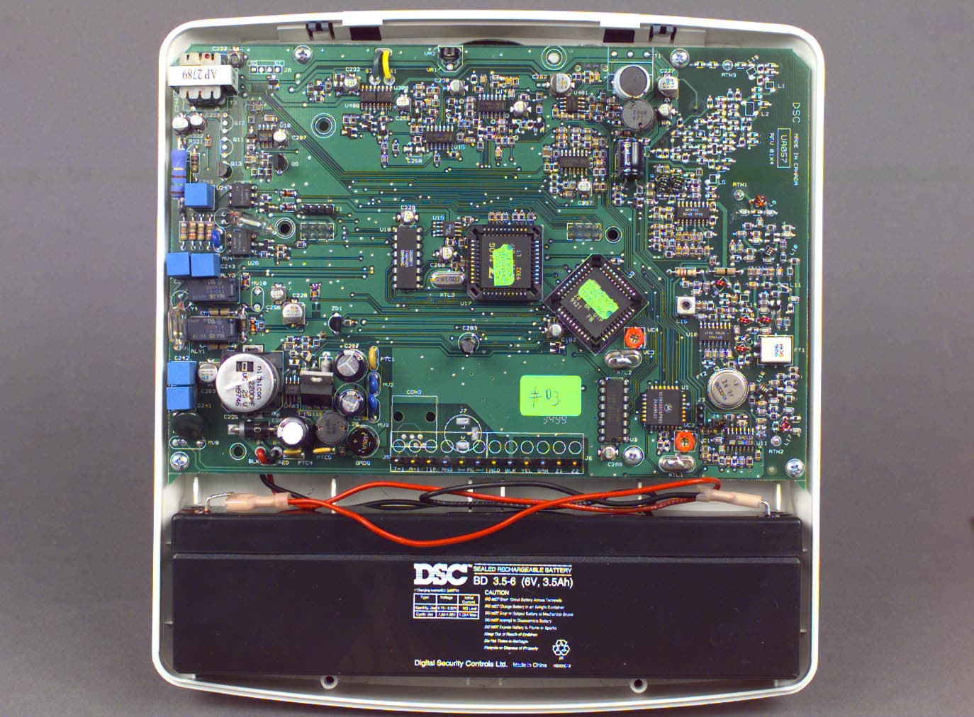
Click to zoom
Application Details
- Equipment Class
- CYY - Communications Receiver used w/Pt 15 Transmitter
- Date of Grant
- Jun 17, 2001
- Application Purpose
- Original Equipment
- Date of Application
- Nov 07, 1999
- Frequency Range
- 924.00000000 - 924.00000000
- Country
- Canada
Documents & Files
Document Text
Text extracted from the exhibit documents filed with the FCC. Open a document above to read the original.
Users Manual
WLS9000 Integral Wireless Alarm System DRAFT Manual Revision 0.01 – Sept 30th, 1999 WARNING: THIS DOCUMENT IS THE PRIVATE PROPERTY OF DIGITAL SECURITY CONTROLS LTD. IT CONTAINS CONFIDENTIAL INFORMATION AND IS NOT TO BE COPIED OR DISTRIBUTED. Digital Security Controls Ltd. 2 Private and Confidential Installation ManualDATE : 09/30/97DRAFT Table of Contents 1.0 INTRODUCTION............................................................................................................................................................. 4 1.1P RODUCT INTENTIONS..................................................................................................................................................................... 4 4.1H ARDWARE DESCRIPTION................................................................................................................................................................ 5 4.2WLS9000 Main Controller .......................................................................................................................................................... 5 4.3Spread Spectrum Wireless........................................................................................................................................................... 5 4.4Voice Prompting Components..................................................................................................................................................... 5 4.5Speaker Control .......................................................................................................................................................................... 5 4.6Piezo............................................................................................................................................................................................ 5 4.1.10Remote Sounder ...................................................................................................................................................................... 5 4.1.11Microphone for Central Station Talk/Listen ........................................................................................................................... 6 4.1Terminal/Jack Connections......................................................................................................................................................... 6 4.4M ISCELLANEOUS............................................................................................................................................................................. 6 4.3P LASTICS......................................................................................................................................................................................... 6 5.0 DETAILED DESCRIPTION OF SOFTWARE FEATURE SET....................................................................................... 7 5.2.1New Function Key Types......................................................................................................................................................... 7 5.2.2Installer Programming ‘Wizard’............................................................................................................................................. 8 5.2.2.1Serial Number Programming................................................................................................................................................................... 8 5.2.2.2Zone Label Programming........................................................................................................................................................................ 8 5.2.2.3Communications Programming............................................................................................................................................................... 9 5.2.2.4Module Placement Test ........................................................................................................................................................................... 9 5.2.3Internal or External Annunciation Selection........................................................................................................................... 9 5.2.4Voice Prompting...................................................................................................................................................................... 9 5.2.5Volume of Annunciation .......................................................................................................................................................... 9 5.2.7Verbal Chime ........................................................................................................................................................................ 10 5.2.8Verbal Alarm ......................................................................................................................................................................... 10 5.2.9Function Keys While in Installer’s Programming................................................................................................................. 11 5.2.10Memo Feature ....................................................................................................................................................................... 11 5.2.11Recording of Custom Labels ................................................................................................................................................. 11 5.2.13Function Key Programming in ESCORT Programming ....................................................................................................... 12 5.2.14New Logs ............................................................................................................................................................................... 12 8.0FUNCTIONAL DESCRIPTION OF...........................................................…
Text truncated - open the document above for the full version.
Attestation Statements
INDUSTRY CANADA STATEMENTS NOTICE: The Industry Canada label identifies certified equipment. This certification means that the equipment meets certain telecommunications network protective, operational and safety requirements. Industry Canada does not guarantee the equipment will operate to the user’s satisfaction. Before installing this equipment, users should ensure that it is permissible to be connected to the facilities of the local telecommunications company. The equipment must also be installed using an acceptable method of connection. The customer should be aware that compliance with the above conditions may not prevent degradation of service in some situations. Repairs to certified equipment should be made by an authorized Canadian maintenance facility designated by the supplier. Any repairs or alterations made by the user to this equipment, or equipment malfunctions, may give the telecommunications company cause to request the user to disconnect the equipment. User should ensure for their own protection that the electrical ground connections of the power utility, telephone lines and internal metallic water pipe system, if present, are connected together. This precaution may be particularly important in rural areas. CAUTION: Users should not attempt to make such connections themselves, but should contact the appropriate electric inspection authority, or electrician, as appropriate. NOTICE: The Ringer Equivalence Number (REN) assigned to each terminal device provides an indication of the maximum number of terminals allowed to be connected to a telephone interface. The termination on an interface may consist of any combination of devices subject only to the requirement that the sum of the Ringer Equivalence Number of all the devices does not exceed 5. The REN of this unit is X.XX. AVIS: L’étiquette de l’Industrie Canada identifie le matériel homologué. Cette étiquette certifie que le matériel est conforme à certaines normes de protection, d’exploitation et de sécurité des réseaux de télécommunications. Industrie Canada n’assure toutefois pas que le matériel fonctionnera à la satisfaction de l’utilisateur. Avant d’installer ce matériel, l’utilisateur doit s’assurer qu’il est permis de le raccorder aux installations de l’entreprise locale de télécommunication. Le matériel doit également être installé en suivant une méthode acceptée de raccordement. L’abonné ne doit pas oublier qu’il est possible que la conformité aux conditions énoncées ci-dessus n’empêchent pas la dégradation du service dans certaines situations. Les réparations de matériel homologué doivent être effectuées par un centre d’entretien canadien autorisé désigné par le fournisseur. La compagnie de télécommunications peut demander à l’utilisateur de débrancher un appareil à la suite de réparations ou de modifications effectuées par l’utilisateur ou à cause de mauvais fonctionnement. Pour sa propre protection, l’utilisateur doit s’assurer que tous les fils de mise à la terre de la source d’énergie électrique, les lignes téléphoniques et les canalisations d’eau métalliques, s’il y en a, sont raccordés ensemble. Cette précaution est particulièrement importante dans les régions rurales. AVERTISSEMENT: L’utilisateur ne doit pas tenter de faire ces raccordements lui-même; il doit avoir recours à un service d’inspection des installations électriques, ou à un électricien, selon le cas. AVIS: L’indice d’équivalence de la sonnerie (IES) assigné à chaque dispositif terminal indique le nombre maximal de terminaux qui peuvent être raccordés à une interface. La terminaison d’une interface téléphonique peut consister en une combinaison de quelques dispositifs, à la seule condition que la somme d’indices d’équivalence de la sonnerie de tous les dispositifs n’excède pas 5. L’indice d’équivalence de la sonnerie (IES) de ce produit est X.XX. This device complies with RSS-210 of Industry Canada. Operation is subject to the following two conditions: (1) this device may not cause interference, and (2) this device must accept any interference, including interference that may cause undesired operation of the device. Ce dispositif satisfait aux exigences d’Industrie Canada, prescrites dans le document CNR-210. son utilisation est autorisée seulement aux conditions suivantes: (1) il ne doit pas produire de brouillage et (2) l’utilisateur du dispositif doit être prêt à accepter tout brouillage radioélectrique reçu, même si ce brouillage est susceptible de compromettre le fonctionnement du dispositif. FCC COMPLIANCE STATEMENT CAUTION: Changes or modifications not expressly approved by Digital Security Controls Ltd. could void your authority to use this equipment. This equipment has been tested and found to comply with the limits for a Class B digital device, pursuant to Part 15 of the FCC Rules. These limits are designed to provide reasonable protection against harmful interference in a residential installation. This equipment generates, uses and can radiate radio frequency energy and, if not installed and used in accordance with the instructions, may cause harmful interference to radio communications. However, there is no guarantee that interference will not occur in a particular installation. If this equipment does cause harmful interference to radio or television reception, which can be determined by turning the equipment off and on, the user is encouraged to try to correct the interference by one or more of the following measures: • Re-orient the receiving antenna. • Increase the separation between the equipment and receiver. • Connect the equipment into an outlet on a circuit different from that to which the receiver is connected. • Consult the dealer or an experienced radio/television technician for help. The user may find the following booklet prepared by the FCC useful: “How to Identify and Resolve Radio/Television Interference Problems”. This booklet is available from the U.S. Government Printing Office, Washington D.C. 20402, Stock # 004-…
Text truncated - open the document above for the full version.
Block Diagram
November 8, 1999 Federal Communications Commission Equipment Authorization Branch 7435 Oakland Mills Road Columbia, Maryland 21046 USA Dear Sir/Madam:Change of Address Information Applicant: Digital Security Controls Ltd. This is to notify you of a change of address and telephone number for Digital Security Controls Ltd. Old address:New Address: 1645 Flint Road3301 Langstaff Road Downsview, Ontario, CanadaConcord, Ontario, Canada M3J 2J6L4K 4L2 New telephone and fax numbers: Tel.: 905-760-3000 or 1-888-888-7838 Fax: 905-760-3030 Contact Name: Kevin Harris Title: Approval Services Manager Tel: 905-760-3000 ext. 378 e-mail: [email protected] Please update your records accordingly. Thank you. Yours truly, Ruby Dulmage Regulatory Submissions Clerk KTL Ottawa Inc.
Cover Letter(s)
November 8, 1999 Federal Communications Commission Equipment Authorization Branch 7435 Oakland Mills Road Columbia, Maryland 21046 USA Dear Sir/Madam:Our File Ref. 9R01881 FCC ID: F5399SS9001 Applicant: Digital Security Controls Ltd. Equipment: WLS9001 Spread Spectrum Receiver FCC Confirmation no.: EA95915 We have successfully electronically filed all the required documentation for an application for certification in accordance with FCC Part 15 on the above mentioned equipment, November 8, 1999. Enclosed, please find a cheque in the amount of $365.00 US, a copy of FCC Remittance Form 159, a copy of the FCC Form 731 confirmation number and a copy of the list of exhibits. If you require additional administrative information, please do not hesitate to contact me at 1-800-563-6336 (extension 232). If you require additional technical information, please contact Mr. Russell Grant at same (extension 223). Thank you in advance for your assistance in this matter. Sincerely, Ruby Dulmage Administrative Clerk KTL Ottawa Encl.
ID Label/Location Info
2" 1" FCC REG. NO.: F53CAN-XXXXX-XX-XREN: X.XX FCC ID: F5399SS9001MADE IN CANADA MODEL NO.: WLS9001Digital Security Controls Ltd. IC:RSS/CNR 210 CANADA: 160 XXX XXX Par tThis device complies with Part 15 and68 of the FCC Rules. Operation is subject to the following two conditions: (1) This device may not cause harmful interference, and (2) this device must accept any interference received, including interference that may cause undesired operation. 00844FRABS The FCC/IC labeling is to be located on the top of the rear housing (08000844) of the unit as shown above. This illustration and labeling are shown 50% of the actual size. DIGITAL SECURITY CONTROLS LTD. ISO 9001 Registered 3301 Langstaff Road, Concord Ontario, Canada L4K 4L2 Phone: 905-760-3000 Toll Free: 1-888-888-7838 Fax: 905-760-3030 TM FCC / IC Labeling for WLS9001 Wireless Control Unit File: [WLS9001 rear housing with fcc+ic info 08000844.cdr] November 4, 1999 Labeling shown above is 100% of actual size
Test Report
Master: ktlPT15BR Date: September 14, 1999 KTL Test Report:9R01881 Applicant:Digital Security Controls Ltd. 3301 Langstaff Road Concord, Ontario L4K 4L2 Equipment Under Test:WLS 9001 Spread Spectrum Receiver (E.U.T.) FCC ID:F5399SS9001 In Accordance With:FCC Part 15, Subpart B Radio Receivers Tested By:KTL Ottawa Inc. 3325 River Road, R.R. 5 Ottawa, Ontario K1V 1H2 Authorized By: R. Grant, Wireless Group Manager Date: Total Number of Pages:17 KTL OttawaFCC PART 15, SUBPART B RADIO RECEIVERS PROJECT NO.: 9R01881 EQUIPMENT: WLS 9001 Spread Spectrum Receiver FCC ID: F5399SS9001 Page 2 of 17 Table Of Contents Section 1. Summary of Test Results .....................................................................................................3 Section 2. Equipment Under Test (E.U.T.) ..........................................................................................5 Section 3. Receiver Antenna Conducted Emissions............................................................................7 Section 4. Radiated Emissions ..............................................................................................................8 Section 5. Powerline Conducted Emissions .......................................................................................11 Section 6. Block Diagrams...................................................................................................................15 Section 7. Test Equipment List ...........................................................................................................17 KTL OttawaFCC PART 15, SUBPART B RADIO RECEIVERS PROJECT NO.: 9R01881 EQUIPMENT: WLS 9001 Spread Spectrum Receiver FCC ID: F5399SS9001 Page 3 of 17 Section 1.Summary of Test Results General: All measurements are traceable to national standards. These tests were conducted on a sample of the equipment for the purpose of demonstrating compliance with FCC Part 15, Subpart B. Measurement procedure ANSI C63.4-1992 was used for all tests. Radiated Emissions were measured on an open area test site. New SubmissionProduction Unit Class II Permissive ChangePre-Production Unit CYY Equipment Code THIS TEST REPORT RELATES ONLY TO THE ITEM(S) TESTED. THE FOLLOWING DEVIATIONS FROM, ADDITIONS TO, OR EXCLUSIONS FROM THE TEST SPECIFICATIONS HAVE BEEN MADE. See “ Summary of Test Data”. NVLAP LAB CODE: 100351-0 TESTED BY: _____________________________________ DATE: ___________________ Kevin Rose, Test Technician KTL Ottawa Inc. authorizes the above named company to reproduce this report provided it is reproduced in its entirety and for use by the company’s employees only. Any use which a third party makes of this report, or any reliance on or decisions to be made based on it, are the responsibility of such third parties. KTL Ottawa Inc. accepts no responsibility for damages, if any, suffered by any third party as a result of decisions made or actions based on this report. This report applies only to the items tested. KTL OttawaFCC PART 15, SUBPART B RADIO RECEIVERS PROJECT NO.: 9R01881 EQUIPMENT: WLS 9001 Spread Spectrum Receiver FCC ID: F5399SS9001 Page 4 of 17 Summary Of Test Data Name Of TestPara. No.Results Antenna Conducted Emissions15.111Not Applicable Radiated Emissions15.109Complies Powerline Conducted Emissions15.107Complies Footnotes For N/A’s: Test Conditions: IndoorTemperature: 20 °C Humidity:31 % OutdoorTemperature: 15 °C Humidity:38 % KTL OttawaFCC PART 15, SUBPART B RADIO RECEIVERS PROJECT NO.: 9R01881 EQUIPMENT: WLS 9001 Spread Spectrum Receiver FCC ID: F5399SS9001 Page 5 of 17 Section 2.Equipment Under Test (E.U.T.) Manufacturer:Digital Security Controls Ltd. Model No.:WLS 9000 Serial No.:None Date Received In Laboratory: October 5, 1999 KTL Identification No.: Item #3 Equipment Details Frequency Range:877.35 MHz (Fixed Local Oscillator) Number of Channels:1 Operating Frequency(ies) of Sample:924 MHz Primary Power Requirement:9 VAC Bandwidth and Emission Designator:Not Applicable Intermediate Frequency(ies):Not Applicable KTL OttawaFCC PART 15, SUBPART B RADIO RECEIVERS PROJECT NO.: 9R01881 EQUIPMENT: WLS 9001 Spread Spectrum Receiver FCC ID: F5399SS9001 Page 6 of 17 Configuration of the Equipment Under Test (E.U.T) EUT 120 VAC 60 Hz Loop Simulator Telephone Cable 120 VAC 60 Hz KTL OttawaFCC PART 15, SUBPART B RADIO RECEIVERS PROJECT NO.: 9R01881 EQUIPMENT: WLS 9001 Spread Spectrum Receiver FCC ID: F5399SS9001 Page 7 of 17 Section 3.Receiver Antenna Conducted Emissions NAME OF TEST: Receiver Antenna Conducted EmissionsPARA. NO.: 15.111 TESTED BY:DATE: Test Results:Complies/Does Not Comply. See attached graphs and table. Measurement Data:See attached graphs and table. KTL OttawaFCC PART 15, SUBPART B RADIO RECEIVERS PROJECT NO.: 9R01881 EQUIPMENT: WLS 9001 Spread Spectrum Receiver FCC ID: F5399SS9001 Page 8 of 17 Section 4.Radiated Emissions NAME OF TEST: Radiated EmissionsPARA. NO.: 15.109(a) TESTED BY: Kevin RoseDATE: October 5, 1999 Minimum Standard: Frequency(MHz)Field Strength (dBμ μμ μV/m @ 3m) 30 - 8840.0 88 - 21643.5 216 - 96046.0 Above 96054.0 Test Results:Complies. The worst-case emission level is 48.5 dBμV/m @ 3m at 1754.69 MHz. This is 5.5 dB below the specification limit. Measurement Data:See attached table. For super-regenerative receivers the receiver is cohered using a signal generator and dipole antenna. Handheld equipment and equipment not designed to be mounted in any fixed orientation, the E.U.T. is tested in three orthogonal axis to obtain worst case results. KTL OttawaFCC PART 15, SUBPART B RADIO RECEIVERS PROJECT NO.: 9R01881 EQUIPMENT: WLS 9001 Spread Spectrum Receiver FCC ID: F5399SS9001 Page 9 of 17 Test Data - Radiated Emissions Test Distance (meters) : 3 Range: A Tower Receiver: ESVP RBW(kHz): 120 Detector: Q-Peak Freq. (MHz) Ant. * Pol. (V/H) Ant. HGT. (m) Table (deg.) RCVD Signal (dBμ μμ μV/m) Ant. Factor (dB)** Amp. Gain (dB)*** Dist. Corr. (dB) Field Strength (dBμ μμ μV/m) Limit (dBμ μμ μV/m) Margin (dB) 877.35E/D4V0.034.634.…
Text truncated - open the document above for the full version.
Contact Information
Applicant
Dan Nita(Approvals Manager)
Technical Contact
Non-Technical Contact
KTL Ottawa Inc.Ruby Dulmage
[email protected]800-563-6336
Test Firm
Nemko Canada Inc.Stuart Beck
Technical Specifications
| # | Rule Parts | Frequency Range | Power Output |
|---|---|---|---|
| 1 | 15B | 924 MHz - 924 MHz | - |
Other Applications from Tyco Safety Products Canada Ltd.

F53252RFLOCK
Jun 05, 2026IQ Lock-PGP, IQ Lock Touch-PGP
Equipment Class
DTS - Digital Transmission System
F5325PGPDC9
Apr 27, 2026PowerG wireless transceiver module
Equipment Class
DSS - Part 15 Spread Spectrum Transmitter
F5325LC203424
Dec 17, 2025Dual Technology Motion Sensor
Equipment Class
FDS - Part 15 Field Disturbance SensorF5324PGPIO9
Dec 04, 2024Wireless Input / Output (I/O) w/wo contact
Equipment Class
DSS - Part 15 Spread Spectrum Transmitter
F5323PGP9934P
Jan 16, 2024Wireless Motion detector with integrated camera
Equipment Class
DSS - Part 15 Spread Spectrum Transmitter