G2X-41004ATelecare Interface Module type 41004A
Tunstall Healthcare (UK) Limited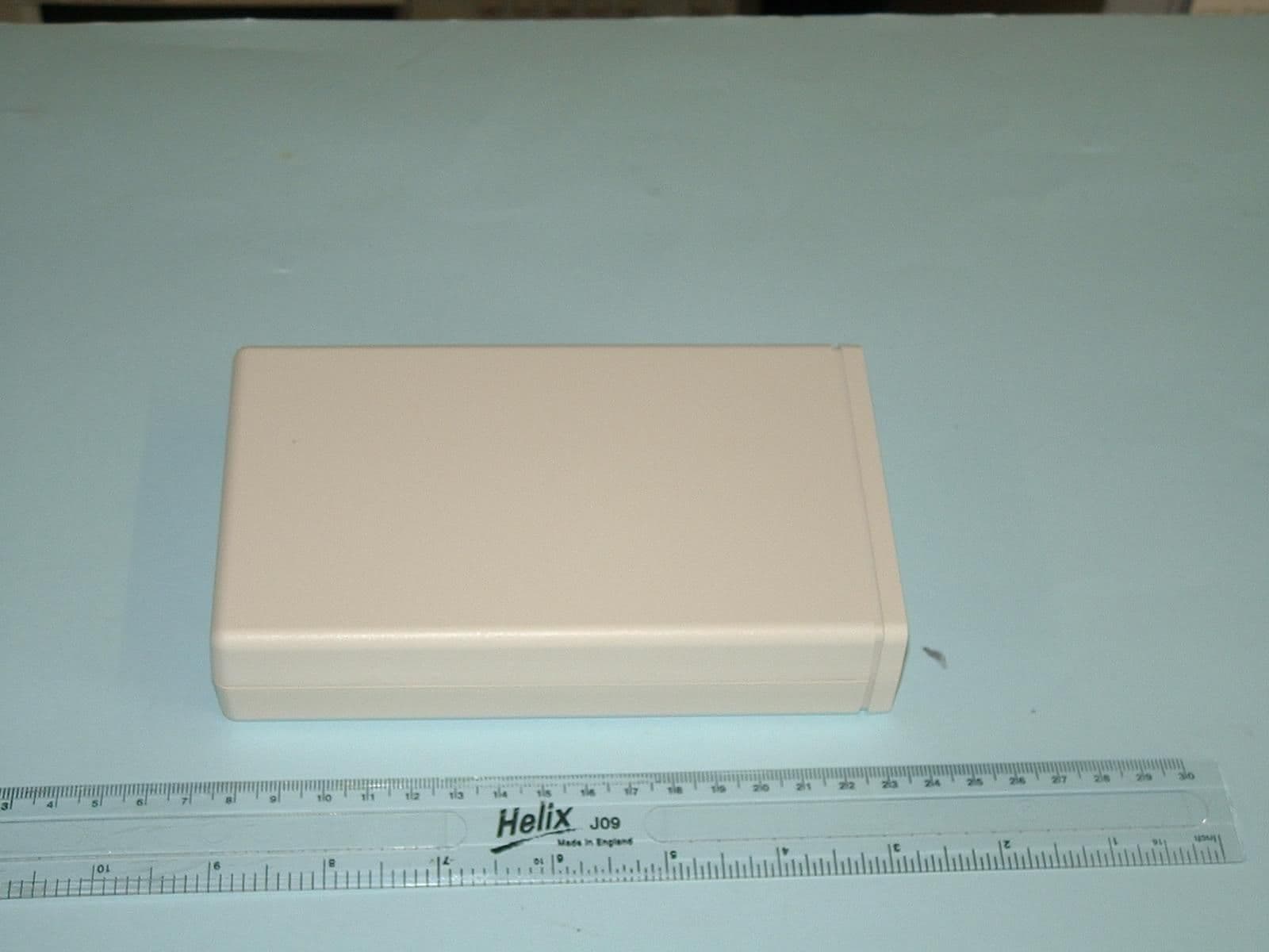
Click to zoom
Application Details
- Equipment Class
- DSC - Part 15 Security/Remote Control Transmitter
- Date of Grant
- Jun 12, 2006
- Application Purpose
- Original Equipment
- Date of Application
- Jun 12, 2006
- Equipment Note
- Telecare Interface Module type 41004A
- Frequency Range
- 311.99700000 - 312.02200000
- Country
- United Kingdom
Documents & Files
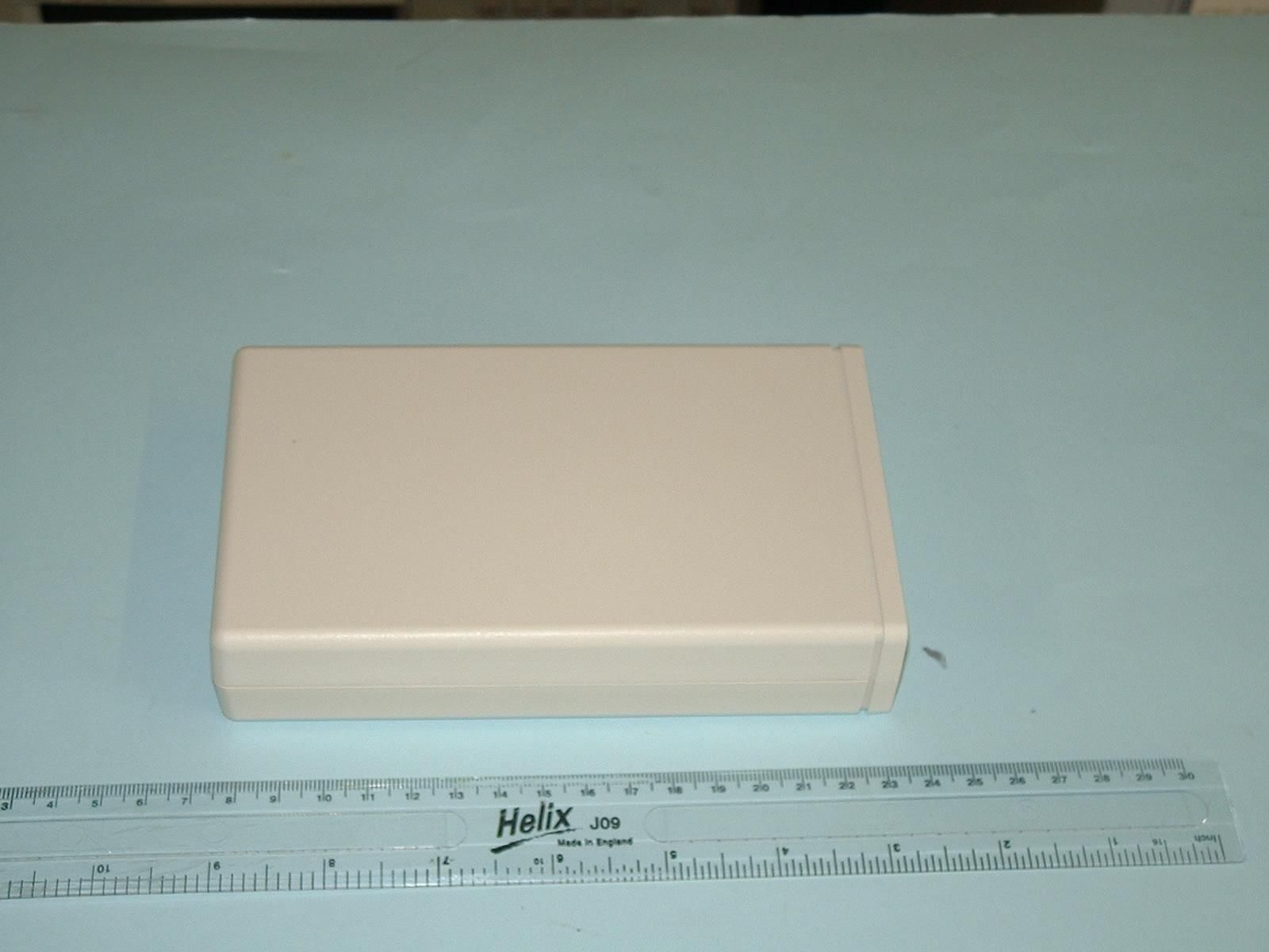
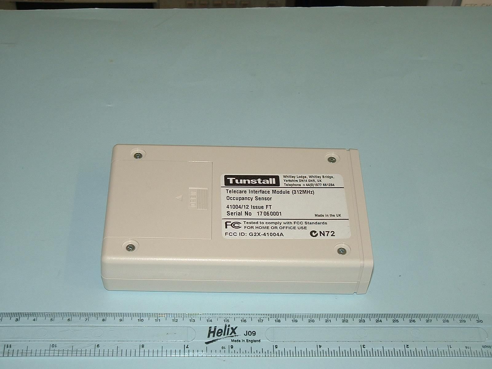

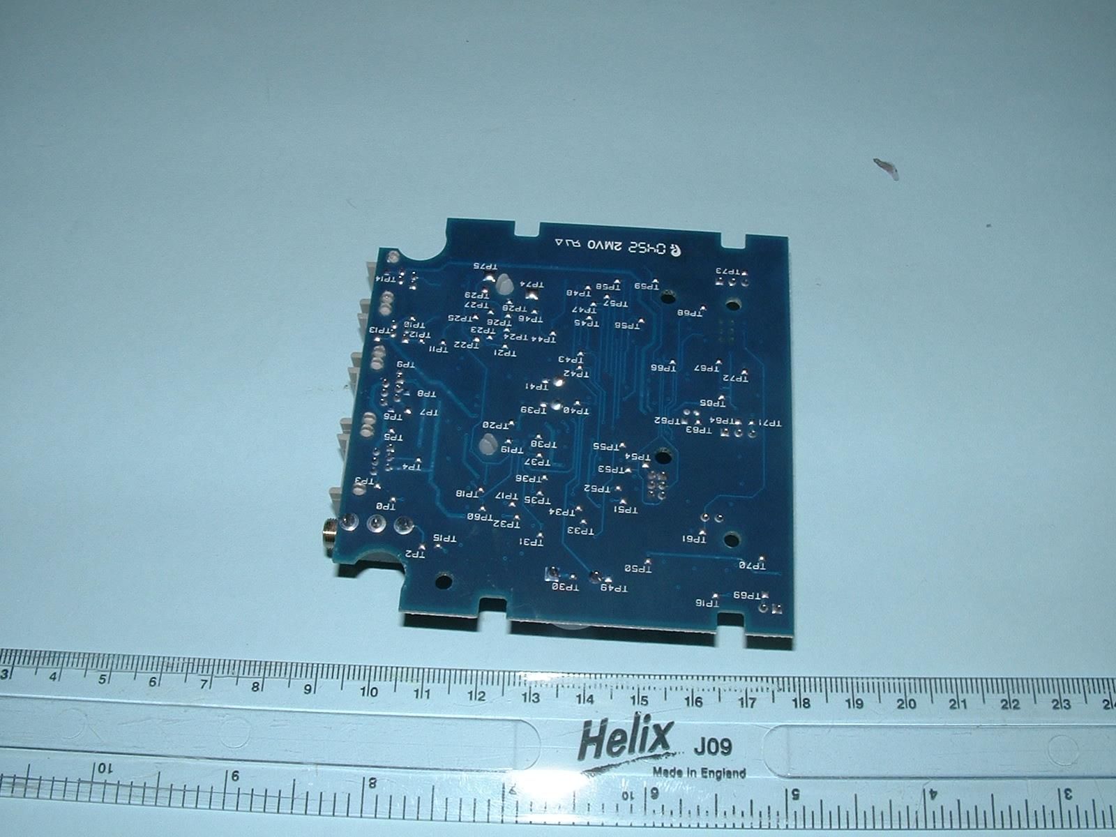
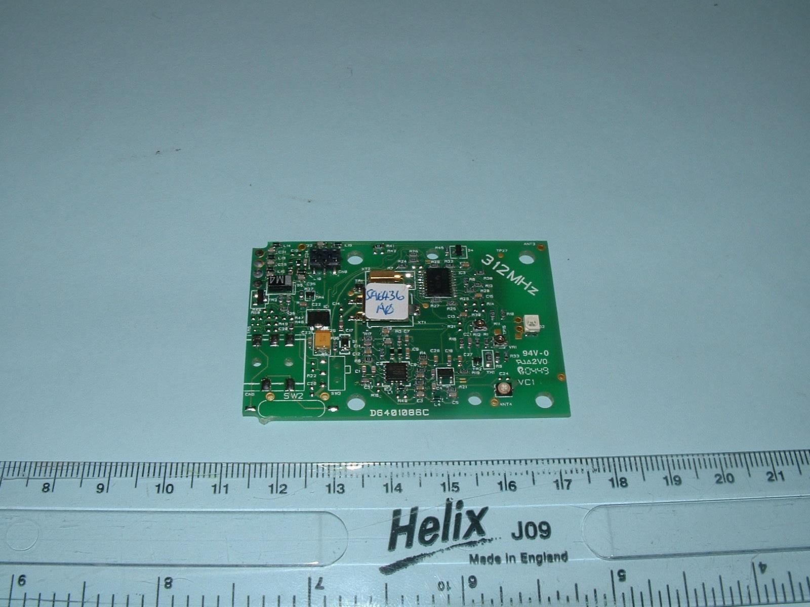
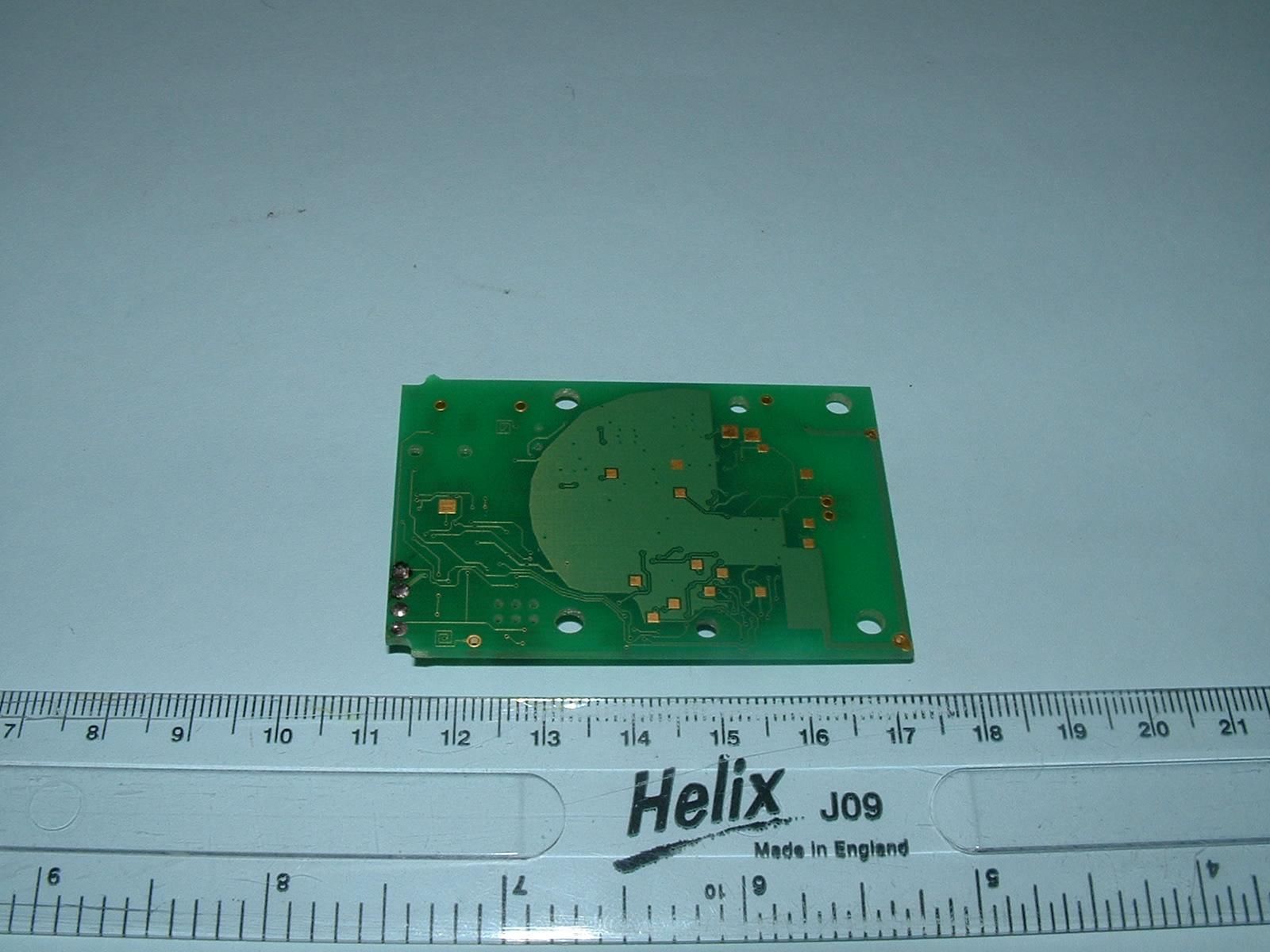
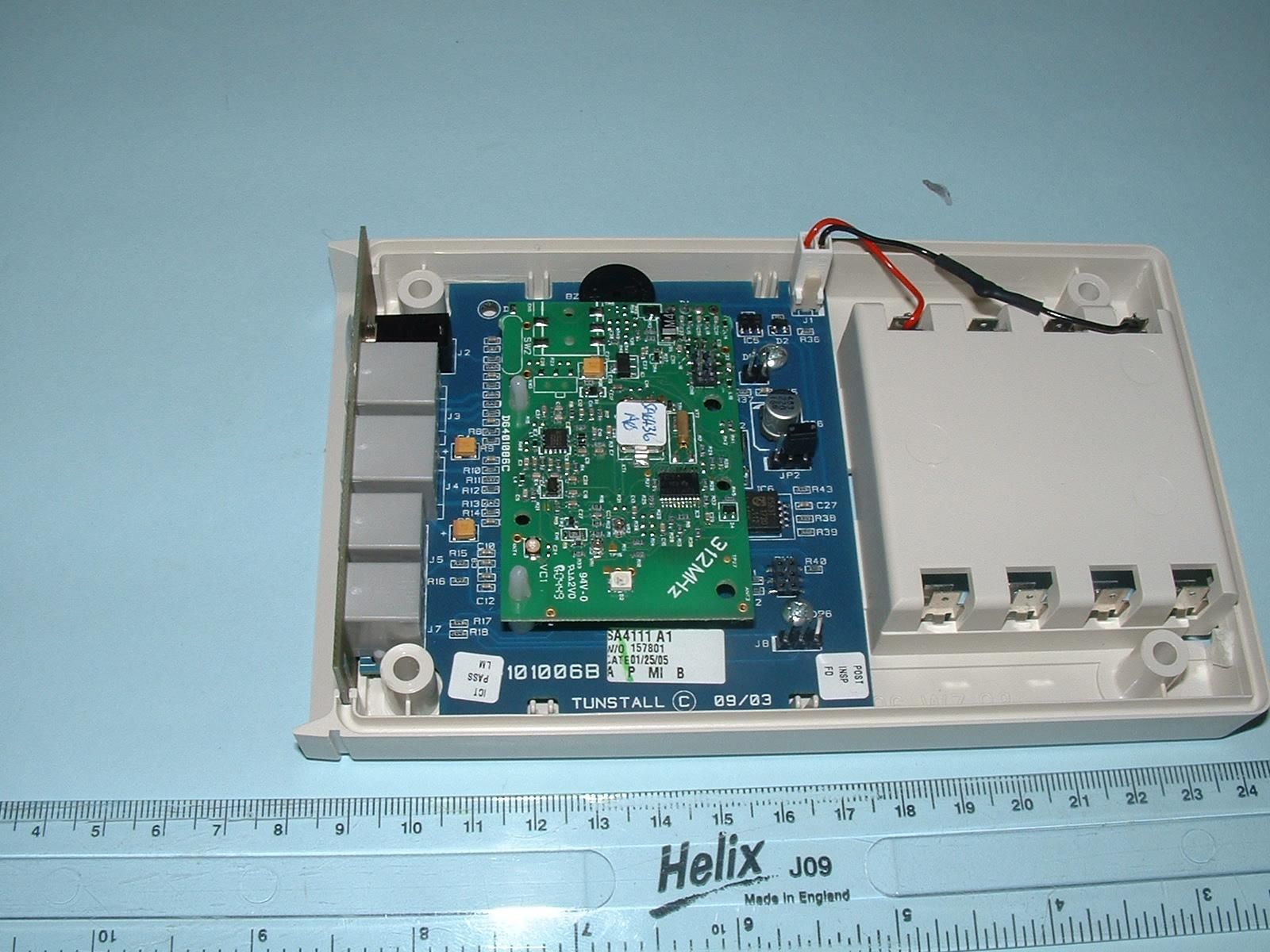
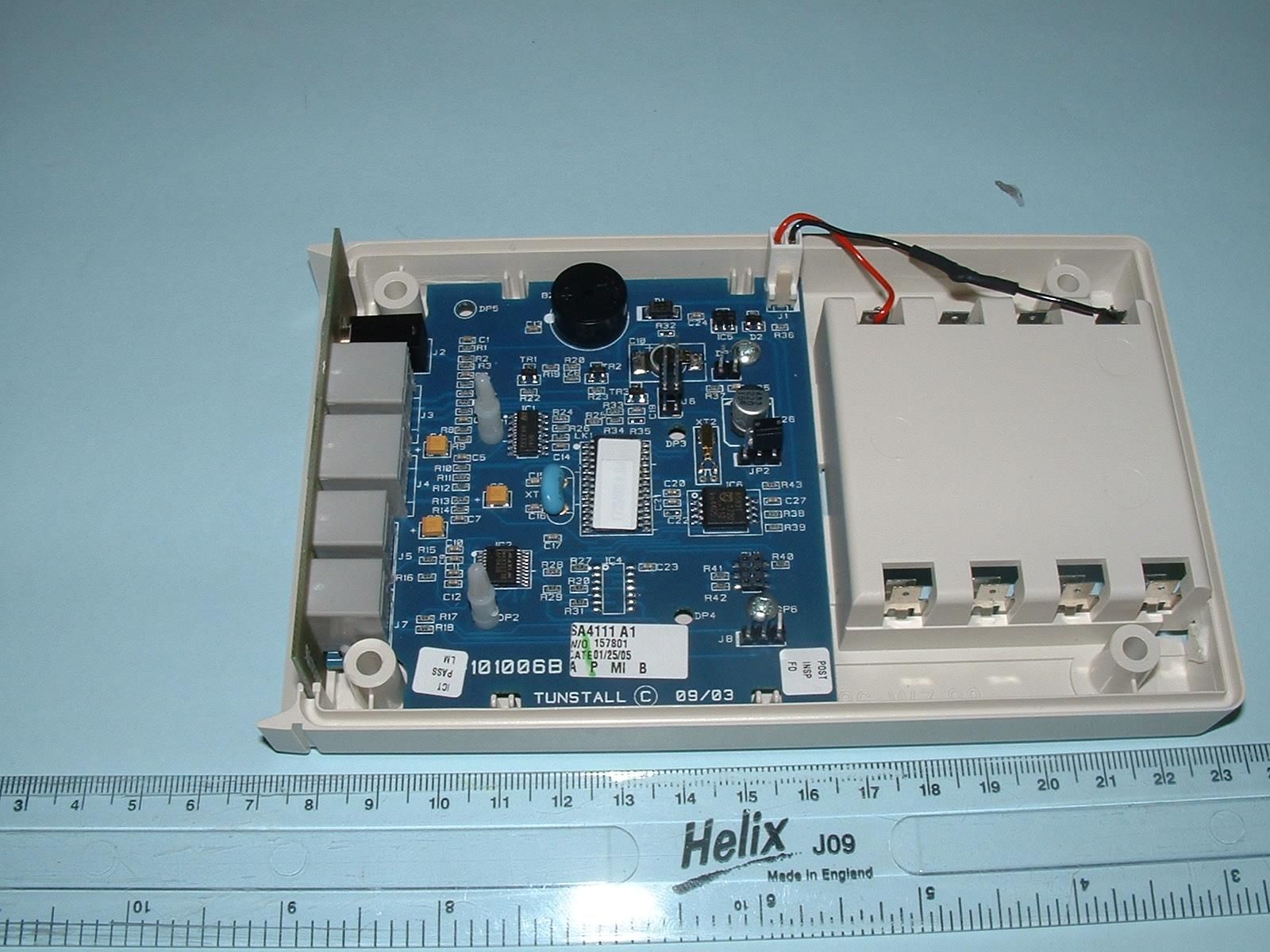
Document Text
Text extracted from the exhibit documents filed with the FCC. Open a document above to read the original.
Users Manual
Document Number: D4107088A Wandering Client Sensor (Model Number 41004/14) User Guide The Wandering Client Sensor monitors door activity and sends an alarm if activity is outside pre set limits. An alarm will also be raised if the door being monitored has been left open. The installer will position all parts of the sensor system in the correct locations according to the installation manual, D4107046A, contained in Palm Kit 41005/16. They will also configure the system. The current configuration is as follows (installer, complete as appropriate): • To arm the monitoring functions set the keyswitch to the “On” position. The sensor will emit a series of double beeps for __ minutes (the arming period) to allow the keyholder to exit (this is similar to a burglar alarm). The wander functions will be armed after the sensor stops beeping. • To disarm the wandering functions set the keyswitch to “Off”. The sensor will emit a long beep and cease monitoring for wandering. • If armed, the system will monitor for activity between __:__ and __:__. During this time if anyone opens the door and the PIR does not detect movement within __:__ (the absence time) the resident will be thought to be “wandering” and an alarm call will automatically be made by the T4000 (or Emergency Call System) to a monitoring centre or personal number . • If the door is left open for longer than __:__ (regardless of the postion of the keyswitch or time of day) then an alarm call will automatically be made by the T4000 (or Emergency Call System) to a monitoring centre. • A light or other mains powered device can be switched on, using X10, when the door is opened. The light will remain switched for __ minutes after the door is closed. Reliance should not be placed on the Wandering Client Sensor, model number 41004/14, for life safety. Outside Light X10 controller X10 Interface Arming Switch Passive Infra Red Motion sensor Magnetic door contacts Bed Occupancy Sensor ! Document Number: D4107088A General Maintenance. The Wandering Client Sensor can be dusted with a dry cloth or vacuumed. It is recommended that a test call is made at regular intervals. DO NOT USE WATER OR A DAMP CLOTH Battery Replacement. The batteries in the Wandering sensor can be replaced with other non-rechargeable AA 1.5V mignon LR6 batteries. The replacements batteries must be fitted within 1 hour of removing the old batteries. Environmental The Wander Sensor will operate between -10°C and +55°C. The wandering client sensor has been approved to the following applicable standards. NOTICES The 312 Wandering sensor has been approved to the following applicable standards. New Zealand and Australia AS/NZ 4268:2003 N72 Canada RSS210 issue 6 sept 2005 IC 1231A-41004A This equipment meets the applicable Industry Canada Equipment Technical Specifications. This is confirmed by the registration number. The abbreviation, IC, before the registration number signifies that registration was performed based on a Declaration of Conformity indicating that Industry Canada Technical Specifications were met. It does not imply that Industry Canada approved the equipment. USA - FCC Approvals This equipment has been tested and found to comply with the limits for a Class B digital device, pursuant to part 15 of the FCC Rules. These limits are designed to provide reasonable protection against harmful interference in a residential installation. This equipment generates, uses and can radiate radio frequency energy and, if not installed and used in accordance with the instructions, may cause harmful interference to radio communications. However, there is no guarantee that interference will not occur in a particular installation. If this equipment does cause harmful interference to radio or television reception, which can be determined by turning the equipment off and on, the user is encouraged to try to correct the interference by one or more of the following measures: • Reorient or relocate the receiving antenna. • Increase the separation between the equipment and receiver. • Connect the equipment into an outlet on a circuit different from that to which the receiver is connected. • Consult the dealer or an experienced radio/TV technician for help. Wandering sensor (Part Number 41004/14) FCC ID: G2X-41004A This Device complies with Part 15 of the FCC Rules. Operation is subject to the following two conditions: (1) This device may not cause harmful interference, and (2) This device must accept any interference received, including interference that may cause undesired operation. Warning Changes or modifications to this unit not expressly approved by the party responsible for compliance could void the user’s authority to operate the equipment.
Users Manual
Document Number: D4107089A Bed/Chair Occupancy Sensor (model number 41004/12) User Guide. The Bed/Chair Occupancy Sensor has been designed to trigger an alarm call if it detects that use of the bed or chair is outside pre defined patterns, which may indicate the user has had a fall or is ill. The installer can configure this sensor in several different ways giving options to turn lights on or extend the time of monitoring after leaving the bed/chair. The installer will position the sensors in their correct locations in accordance with the installation manual. They will also configure the system. The current configuration is indicated below (installer, complete as appropriate): • Between __:__ and __:__ the sensor will monitor for occupancy. During this time if absence is detected for more than _____ then an alarm call will automatically be made by the T4000 (or Emergency Call System) to a monitoring centre or personal number. In addition, an “extend” button may be fitted. This will allow the user to increase the period before the alarm is raised to _____ by pressing the button at any time prior to the alarm call being sent. • Between __:__ and __:__ the device can use X10 to switch on a lamp automatically once out of bed and switch off once back into bed. • If occupancy is not detected before __:__ (the not in bed by time) then an alarm call will automatically be made by the T4000 (or Emergency Call System) to a monitoring centre or personal number. • If occupancy continues after __:__ (the still in bed by time) then an alarm call will automatically be made by the T4000 (or Emergency Call System) to a monitoring centre or personal number. If a lamp is connected to an X10 controller, the switch on the lamp should be permanently ON. The X10 controller will automatically switch the light on and off. Reliance should not be placed on the Bed/Chair Occupancy Sensor, model number 41004/12, for life safety. ! Bedside Lamp X10 controller X10 Interface Extend Button First Bed Pad Second Bed pad Bed Occupancy Sensor Document Number: D4107089A General Maintenance. To ensure proper operation of the sensor please ensure that the blue pad sensing bed or chair occupancy remains positioned correctly in accordance with the installation instructions. It is recommended that a test call is made at regular intervals. Battery Replacement: The batteries in the Occupancy sensor can be replaced with other non-rechargeable AA 1.5V mignon LR6 batteries. The replacements batteries must be fitted within 1 hour of removing the old batteries. Environmental The Occupancy Sensor will operate between 14°F and 131°F (-10°C and +55°C). NOTICES The 312 Occupancy sensor has been approved to the following applicable standards. New Zealand and Australia Approvals AS/NZ 4268:2003 N72 Canada RSS210 issue 6 sept 2005 IC 1231A-41004A This equipment meets the applicable Industry Canada Equipment Technical Specifications. This is confirmed by the registration number. The abbreviation, IC, before the registration number signifies that registration was performed based on a Declaration of Conformity indicating that Industry Canada Technical Specifications were met. It does not imply that Industry Canada approved the equipment. USA - FCC Approvals This equipment has been tested and found to comply with the limits for a Class B digital device, pursuant to part 15 of the FCC Rules. These limits are designed to provide reasonable protection against harmful interference in a residential installation. This equipment generates, uses and can radiate radio frequency energy and, if not installed and used in accordance with the instructions, may cause harmful interference to radio communications. However, there is no guarantee that interference will not occur in a particular installation. If this equipment does cause harmful interference to radio or television reception, which can be determined by turning the equipment off and on, the user is encouraged to try to correct the interference by one or more of the following measures: • Reorient or relocate the receiving antenna. • Increase the separation between the equipment and receiver. • Connect the equipment into an outlet on a circuit different from that to which the receiver is connected. • Consult the dealer or an experienced radio/TV technician for help. Occupancy sensor (Part Number 41004/12) FCC ID: G2X-41004A This Device complies with Part 15 of the FCC Rules. Operation is subject to the following two conditions: (1) This device may not cause harmful interference, and (2) This device must accept any interference received, including interference that may cause undesired operation. Warning Changes or modifications to this unit not expressly approved by the party responsible for compliance could void the user’s authority to operate the equipment.
Users Manual
D4107041A Page 1 Enuresis Sensor Part Number (41004/21) Installation and User Instructions Functionality The Enuresis Sensor is a Telecare Sensor intended for use with the following Tunstall Emergency Call Equipment: – Telecom 4000+ and Telecare Overlay. The Enuresis Sensor comprises a Telecare Interface Module (TIM) fitted with Enuresis software (41004/20) and a Moisture Sensing Mat (S2209050). The intended use of the Enuresis Sensor is to ensure client comfort by signalling an alarm condition (by radio) in the event of the client’s bed becoming wet. The Enuresis Sensor is not sold as a Medical Device and therefore should not be used for the diagnosis, prevention, monitoring, treatment of or alleviation of enuresis. The Enuresis Sensor is powered by 4 AA batteries with a minimum battery life of 2 years with typical usage. The Enuresis Sensor automatically monitors the condition of the batteries and as they approach the end of their life, the Enuresis Sensor will signal (by radio) this event to the T4000 every 7 days (until the batteries are replaced or expire completely). Installation 1. Install the Enuresis Sensor by placing the Moisture Sensing Mat underneath a cotton top sheet and on top of any protective sheet. The shiny side of the Moisture Sensing Mat should be uppermost and the centre of the mat should be located at the position where bed wetting is most likely. 2. Insert the supplied batteries into the battery compartment in the base of the TIM in accordance with the raised markings in the base of the battery compartment. A single beep will be heard if the batteries are inserted correctly. 3. Connect the plug at the end of the Moisture Sensing Mat cable to the socket labelled IP4/Prog on the front panel of the TIM. It is important that the blanking plugs fitted in the other sockets of the TIM are left in place. 4. Program the Enuresis Sensor into the T4000+ (or Telecare Overlay system) using the procedure detailed below. 5. The TIM should be located in a convenient place nearby, ensuring the cable is safely routed. It is important that the TIM is not placed in a position where it may become wet. For optimum radio performance the TIM should be mounted away from metallic surfaces. D4107041A Page 2 Assigning to an emergency response system Place your Tunstall T4000+ (or Telecare Overlay system) into radio trigger programming mode. ‘Short’ the two metal studs on the Incontinence Sensing Mat together with a metallic object (e.g. a key) as shown in the photograph below until a beep is heard. This signifies the radio transmission has occurred. The T4000+ (or Telecare Overlay system) will beep, indicating that the sensor has been programmed into it. Leave programming mode in accordance with the T4000 Advanced User Guide. Check that the Enuresis Sensor has been correctly programmed into the T4000+ (or Telecare Overlay system) by raising a test call. The test call can be raised by generating a radio transmission from the Enuresis Sensor in the same manner as described above. User Instructions The Enuresis Sensor will signal an alarm event once when a wet bed condition is detected. After a wet bed event has occurred the Enuresis Sensor can be reset by disconnecting the Moisture Sensing Mat from the TIM, cleaning it with detergent and a non-abrasive damp cloth, and then drying it with a suitable non-abrasive absorbent cloth. Once the Moisture Sensing Mat is dry, reconnect it to the TIM and replace in the dry bed. It is possible that sweating during the night may cause false triggering of the Enuresis Sensor. If this is the case then a folded cotton sheet or bath towel should be placed above the Moisture Sensing Mat Service Information The TIM contains no user serviceable parts other than the batteries. The batteries should be replaced when indication is received that the Enuresis Sensor is in the low battery condition. Replacement batteries should be of the alkaline type and from a reputable manufacturer e.g. Duracell. The battery replacement procedure is as detailed in Step 1 of the Installation Instructions. Old batteries should be disposed of in accordance with local regulations. Should the Moisture Sensing Mat need to be replaced you can order a new mat from Tunstall by quoting Part Number S2209050. D4107041A Page 3 NOTICES The 312 Enuresis sensor has been approved to the following applicable standards. New Zealand and Australia Approvals AS/NZ 4268:2003 N72 Canada RSS210 issue 6 sept 2005 IC 1231A-41004A This equipment meets the applicable Industry Canada Equipment Technical Specifications. This is confirmed by the registration number. The abbreviation, IC, before the registration number signifies that registration was performed based on a Declaration of Conformity indicating that Industry Canada Technical Specifications were met. It does not imply that Industry Canada approved the equipment. USA – FCC Approvals This equipment has been tested and found to comply with the limits for a Class B digital device, pursuant to part 15 of the FCC Rules. These limits are designed to provide reasonable protection against harmful interference in a residential installation. This equipment generates, uses and can radiate radio frequency energy and, if not installed and used in accordance with the instructions, may cause harmful interference to radio communications. However, there is no guarantee that interference will not occur in a particular installation. If this equipment does cause harmful interference to radio or television reception, which can be determined by turning the equipment off and on, the user is encouraged to try to correct the interference by one or more of the following measures: • Reorient or relocate the receiving antenna. • Increase the separation between the equipment and receiver. • Connect the equipment into an outlet on a circuit different from that to which the receiver is connected. • Consult the dealer or an experienced radio/TV technician for help. Enuresis sensor (Part …
Text truncated - open the document above for the full version.
Test Report
TRL COMPLIANCE LTD M OSS VIEW NIPE LANE UP HOLLAND WEST LANCASHIRE WN8 9PY UNITED KINGDOM T ELEPHONE +44 (0)1695 556666 FAX +44 (0)1695 557077 E-MAIL [email protected] www.trlcompliance.com 0728 TEST REPORT NO: RU1242/6987 COPY NO: 2 ISSUE NO: 1 FCC IDS: G2X-41004A REPORT ON THE CERTIFICATION TESTING OF A TUNSTALL TELECOM Ltd WANDERING DETECTOR, OCCUPANCY SENSOR and ENURESIS SENSOR WITH RESPECT TO THE FCC RULES CFR 47, PART 15.231 February 2006 INTENTIONAL RADIATOR SPECIFICATION TEST DATE: 2 nd – 8 th May 2006 TESTED BY: D WINSTANLEY APPROVED BY: P GREEN EMC PRODUCT MANAGER DATE: 12 th June 2006 Distribution: Copy Nos: 1. Tunstall Telecom Ltd 2. FCC EVALUATION LABORATORIES 3. TRL Compliance Ltd THIS DOCUMENT MAY BE REPRODUCED ONLY IN ITS ENTIRETY AND WITHOUT CHANGE TRL RF335U iss01B RU1242/6987 Page 2 of 31 CONTENTS PAGE CERTIFICATE OF CONFORMITY & COMPLIANCE 3 APPLICANT’S SUMMARY 4 EQUIPMENT TEST CONDITIONS 5 TESTS REQUIRED 5 CONFIGURATION DIAGRAMS 6 TEST RESULTS 7-11 ANNEX PHOTOGRAPHS A PHOTOGRAPH No. 1: Test setup – Enuresis Sensor PHOTOGRAPH No. 2: Test setup – Occupancy Sensor PHOTOGRAPH No. 3: Test setup – Wandering Detector PHOTOGRAPH No. 4: Transmitter front view PHOTOGRAPH No. 5: Transmitter rear view PHOTOGRAPH No. 6: Control PCB track side PHOTOGRAPH No. 7: Control PCB component side PHOTOGRAPH No. 8: RF PCB track side PHOTOGRAPH No. 9: RF PCB component side APPLICANT’S SUBMISSION OF DOCUMENTATION LIST B BAND OCCUPANCY PLOT C TRANSMITTER TIMING PULSE D EQUIPMENT CALIBRATION E MEASUREMENT UNCERTAINTY F Notes: 1. Component failure during test YES NO [ ] [X] 2. If Yes, details of failure: 3. The facilities used for the testing of the product contain in this report are FCC Listed. 4. The contents of the attached applicants declarations and other supplied information are not covered by the scope of this laboratory’s UKAS or FCC accreditations’ and is provided in good faith. TRL RF335U iss01B RU1242/6987 Page 3 of 31 CERTIFICATE OF CONFORMITY & COMPLIANCE FCC IDENTITY: G2X-41004A PURPOSE OF TEST: Certification TEST SPECIFICATION: FCC RULES CFR 47, Part 15.231 February 2006 TEST RESULT: Compliant to Specification EQUIPMENT UNDER TEST: Wandering Detector Occupancy Sensor Enuresis Sensor EQUIPMENT SERIAL No: 1706001 & 1706002 ITU: EMISSION CODE: 25k6F1D EQUIPMENT TYPE: Monitoring sensors PRODUCT USE: Personal Care Monitoring & Alarm System CARRIER EMISSION: 5821.0 μV/m (Enuresis Sensor – Worst case emission) ANTENNA TYPE: Integral ALTERNATIVE ANTENNA: Not Applicable FREQUENCY OF OPERATION: 312 MHz CHANNEL SPACING: Not applicable, wideband NUMBER OF CHANNELS: 1 FREQUENCY GENERATION: SAW Resonator [ ] Crystal [X] Synthesiser [ ] MODULATION METHOD: Amplitude [ ] Digital [X] Angle [ ] POWER SOURCE(s): +6Vdc TEST DATE(s): 2 nd – 8 th May 2006 ORDER No(s): 57359 APPLICANT: Tunstall Telecom Ltd ADDRESS: Whitley Lodge Whitley Bridge Yorkshire DN14 0HR TESTED BY: D WINSTANLEY APPROVED BY: P GREEN EMC PRODUCT MANAGER TRL RF335U iss01B RU1242/6987 Page 4 of 31 APPLICANT’S SUMMARY EQUIPMENT UNDER TEST (EUT): Wandering Detector Occupancy Sensor Enuresis Sensor EQUIPMENT TYPE: Monitoring sensors SERIAL NUMBER OF EUT: 1706001 & 1706002 PURPOSE OF TEST: Certification TEST SPECIFICATION(s): FCC RULES CFR 47, Part 15.231 February 2006 TEST RESULT: COMPLIANT Yes No [X] [ ] APPLICANT’S CATEGORY: MANUFACTURER IMPORTER DISTRIBUTOR TEST HOUSE AGENT [X] [ ] [ ] [ ] [ ] APPLICANT’S ORDER No(s): 57359 APPLICANT’S CONTACT PERSON(s): Mr C Marcus E-mail address: [email protected] APPLICANT: Tunstall Telecom Ltd ADDRESS: Whitley Lodge Whitley Bridge Yorkshire DN14 0HR TEL: +44 (0) 1977 661234 FAX: +44(0) 1977 662452 EUT(s) COUNTRY OF ORIGIN: United Kingdom TEST LABORATORY: TRL Compliance UKAS ACCREDITATION No: 0728 TEST DATE(s) 2 nd – 8 th May 2006 TEST REPORT No: RU1242/6987 TRL RF335U iss01B RU1242/6987 Page 5 of 31 EQUIPMENT TEST / EXAMINATIONS REQUIRED 1. TEST/EXAMINATION RULE PART DETECTOR APPLICABILITY Intentional Emission Frequency: 15.231(b) Quasi Peak Yes Intentional Emission Field Strength: 15.231(b) Quasi Peak Yes Intentional Emission Band Occupancy: 15.231(c) Peak Yes Intentional Emission ERP (mW): - - No Spurious Emissions – Conducted: 15.207 - No Spurious Emissions – Radiated <1000MHz: 15.231(b) 15.209 Quasi Peak Yes Spurious Emissions – Radiated >1000MHz: 15.231(b) 15.209 Quasi Peak Average Yes Maximum Frequency of Search: 15.33 - Yes Antenna Arrangements Integral: 15.203 - Yes Antenna Arrangements External Connector: 15.204 - N/A Restricted Bands 15.205 - Yes Extrapolation Factor 15.31(f) - Yes 2. Product Use: Personal Care Monitoring & Alarm System 3. Emission Designator: 25k6F1D 4. Duty Cycle: <100% 5. Transmitter bit or pulse rate and level: 1000bps 6. Temperatures: Ambient (Tnom) 16 o C 7. Supply Voltages: Vnom +6Vdc Note: Vnom voltages are as stated above unless otherwise shown on the test report page Single channel [X] Two channel [ ] 8. Equipment Category: Multi-channel [ ] Narrowband [ ] Wideband [X] 9. Channel spacing: The 3 models, tested under this report differ in the connected peripherals only. The PCBs and RF circuitry for all 3 models are the same. As the units are identical the FCC ID used is the same with a variation of model number according to the sensor(s) utilised. See configuration diagrams on next page. TRL RF335U iss01B RU1242/6987 Page 6 of 31 Configuration diagrams Enuresis Sensor Occupancy Sensor Wanderer Detector EUT Enuresis Sensor Occupancy Sensor EUT X10 switch socket Enable/Disable Switch EUT X10 switch socket Door Read Switch PIR Detector TRL RF335U iss01B RU1242/6987 Page 7 of 31 TRANSMITTER TESTS TRANSMITTER SPURIOUS EMISSIONS – RADIATED – PART 15.209 Ambient temperature = 16 o C(<1GHz) 3m measurements <1GHz [X] Relative humidity = 48% (<1GHz), 0.3m measurements >1GHz [X] Conditions = Open Area Test Site (OATS) 3m extrapolated from 0.3m [X] Supply voltage = +6Vdc Channel number = 1 Wandering Detector FREQ (MHz) MEAS Rx (dBμV) CABLE LOSS (dB) ANT FACT FIE…
Text truncated - open the document above for the full version.
Test Setup Photos
TRL RF335U iss01B RU1242/6987 Page 13 of 31 PHOTOGRAPH No. 1 TEST SETUP – ENURESIS SENSOR
Test Setup Photos
TRL RF335U iss01B RU1242/6987 Page 14 of 31 PHOTOGRAPH No. 2 TEST SETUP – OCCUPANCY SENSOR
Contact Information
Applicant
Mark Jennings(Chief Engineer)
Technical Contact
Tunstall Group LtdChris Marcus
[email protected]+44 1977 661234
Whitley Lodge · Doncaster · United Kingdom
Test Firm
TRL Compliance LtdJohn Charters
Technical Specifications
| # | Rule Parts | Frequency Range | Power Output |
|---|---|---|---|
| 1 | 15.231 | 311.997 MHz - 312.022 MHz | - |
Other Applications from Tunstall Healthcare (UK) Limited
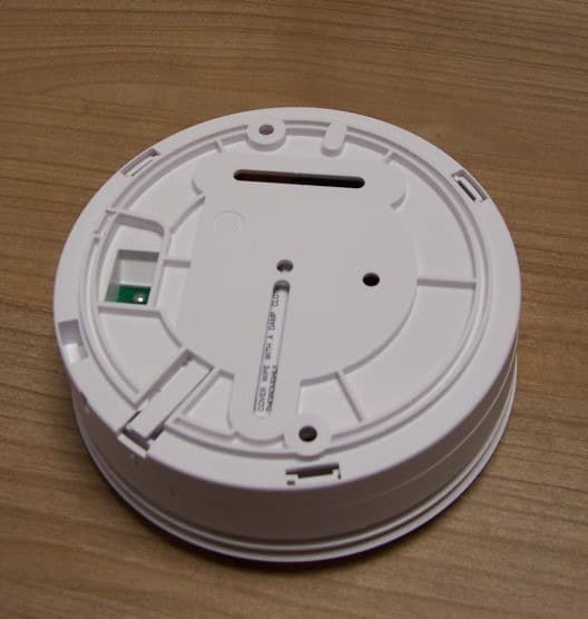
G2X-646041E
May 14, 2013312 Ei Smoke Alarm Model 64604/14
Equipment Class
DSC - Part 15 Security/Remote Control Transmitter
G2X-66004V
Dec 17, 201266004/09 iVi Personal Fall Detector.
Equipment Class
DXX - Part 15 Low Power Communication Device Transmitter
G2X-6360412
Dec 06, 201263604/12 Amie Personal Fall Alarm
Equipment Class
DXX - Part 15 Low Power Communication Device Transmitter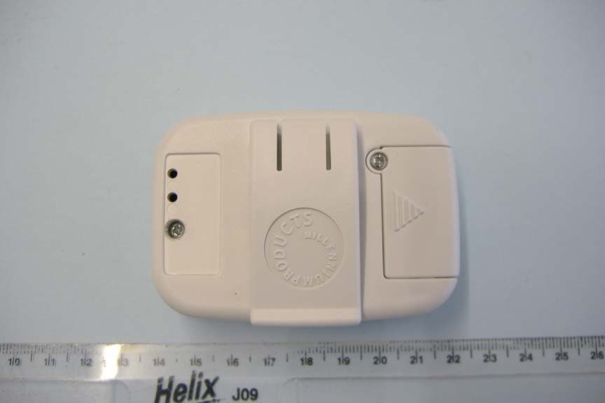
G2X66004
Jan 29, 2008312 Fall Detector
Equipment Class
DSC - Part 15 Security/Remote Control Transmitter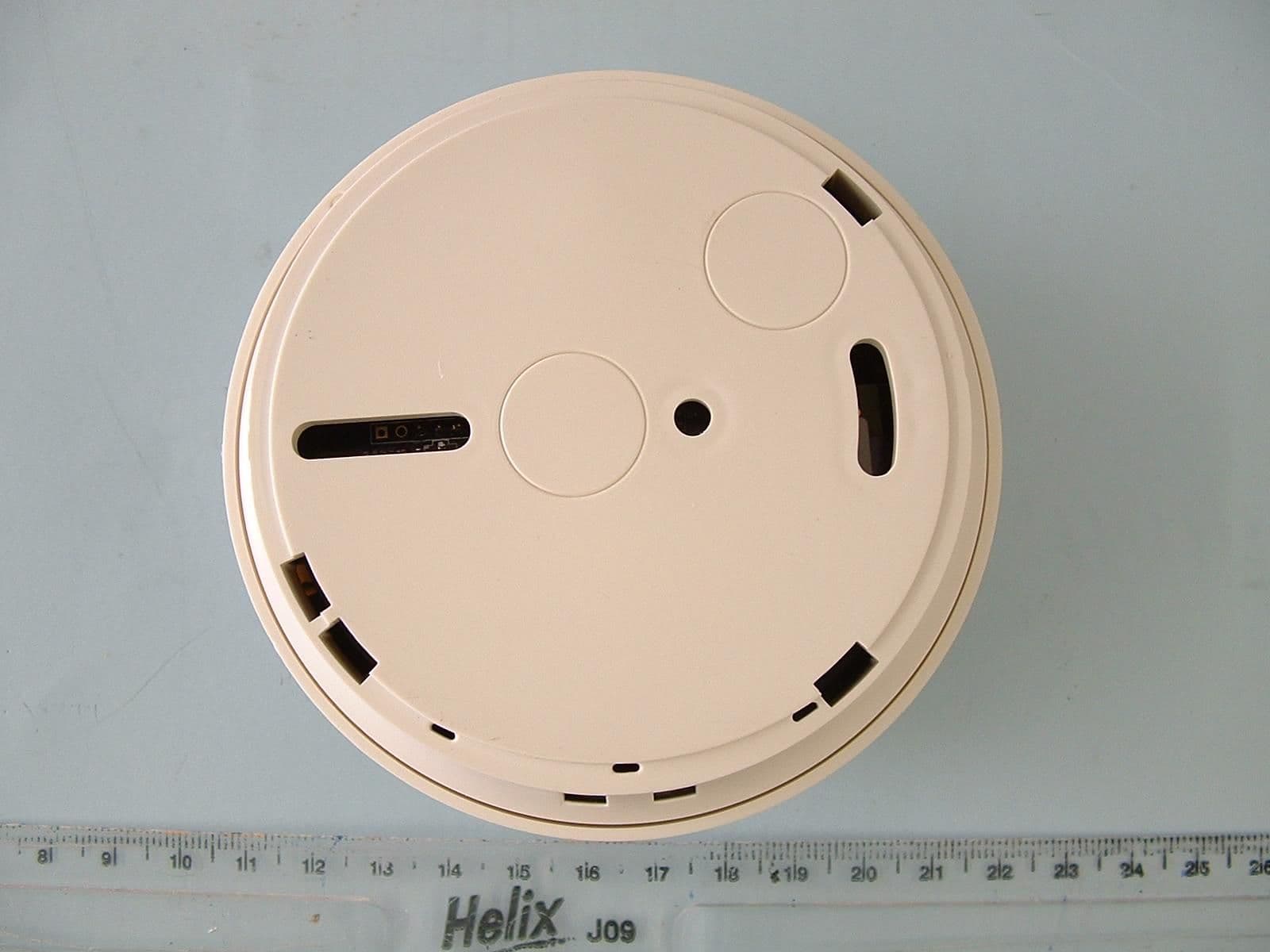
G2X-6460474A
Dec 15, 2006Radio Smoke Detector model 64604/74
Equipment Class
DSC - Part 15 Security/Remote Control Transmitter