G2X-636041263604/12 Amie Personal Fall Alarm
Tunstall Healthcare (UK) Limited
Click to zoom
Application Details
- Equipment Class
- DXX - Part 15 Low Power Communication Device Transmitter
- Date of Grant
- Dec 06, 2012
- Application Purpose
- Original Equipment
- Date of Application
- Dec 06, 2012
- Equipment Note
- 63604/12 Amie Personal Fall Alarm
- Frequency Range
- 312.00000000 - 312.00000000
- Country
- United Kingdom
Documents & Files
Document Text
Text extracted from the exhibit documents filed with the FCC. Open a document above to read the original.
Users Manual
Tunstall Vi/Vi+ User Guide For installation instructions please visit tunstallamac.com/?????? Your Tunstall Vi home console unit The Tunstall home console unit is connected to the mains power supply and your telephone line. It enables you to generate a call for help when and if you need it by immediately contacting a monitoring centre who will be able to provide you with the assistance you require. Your Help Activator Your Help Activator is wirelessly connected to your Tunstall home console unit and enables you to generate a call for help from anywhere in your home or garden. The personal trigger should be worn at all times and can be worn around the neck or on the wrist using the attachments supplied. Help Activators are water resistant (to IP67 standard) up to 1m. It can be worn in the shower however wearing it in the bath should be avoided where possible. The Help Activator has the below features: *NOTE: The trigger will automatically send a notification call via the home console unit to the monitoring centre when its battery is low. Radio Antenna Reset Button (Green) Speaker Help Button (Red) Status light (Red/Green) Microphone Optional Services Button (Yellow) Waterproof Auto Low Battery* Up to 390ft radio range (free space) For installation instructions please visit tunstallamac.com/?????? Using the PERS Making an alarm call Press the red button on the Help Activator or the red alarm button on the home console unit. The home console unit will announce ‘Do not worry your alert system is dialling for assistance’. The call will be answered by an operator at the response center. Tell the operator why you have generated the alarm call and they will arrange for assistance. Cancelling a Help call Wait 5 seconds (after the alarm button is pressed) and press the green reset button. The home console unit will announce ‘The emergency call has been cancelled’. This in-built delay prevents accidental cancellation of an alarm. Answering calls remotely via the portable Help Activator The Help Activator can be used to answer incoming telephone calls by pressing the Help Activator button while the telephone is ringing. When pressed, the home console unit will answer the call in hands-free mode using the loudspeaker. To revert to handset mode, just pick up the handset of a connected telephone. To end a hands-free call, press the button on the Help Activator again or press the reset button. Calls can also be answered in hands-free mode at the home console unit by pressing the reset button. For installation instructions please visit tunstallamac.com/?????? HELP RESET CUSTOMER CARE False alarms If you accidentally raise a false alarm, please do not worry as your response center is always happy to hear from you and the raising of the alarm acts as a useful test of your home console unit. What the Warning/Status lights on the home console unit indicate The home console unit has warning and status lights to clearly show the unit’s status lights on the home console unit provide indications of its status based on the below. The light on the Help Activator indicates When pressed the red light on the Help Activator will light up. This is to indicate that the button has been pressed. If the light flashes when pressed this indicates that the Help Activator battery is low and should be replaced. Home/Away Button (Yellow) Home console unit status On Away mode Off Home mode Flashing Intruder entry/exit time period Status LED (Green/Red) Home console unit status Green LED on Normal mode Red LED flashing (1 every 4 seconds) Low battery Red LED flashing (1 every second) Telephone line disconnected Red/Green flashing Radio blocking detected Alarm Button (Red) Home console unit status On Normal mode Flashing (1 every 4 seconds) Normal mode running on battery Flashing (1 every second) Alarm mode For installation instructions please visit tunstallamac.com/?????? How to respond to announcements Announcement What to do ‘Warning – telephone line disconnected’ Check the home console unit is plugged into a working telephone socket ‘Warning – there is no mains power’ Check the home console unit is plugged into a working electrical socket ‘Warning - Radio blocking detected’ Check that the home console unit is not close to any other electrical devices such as a computer, television, fan, mobile phone. If so, turn-off or move the equipment away from the home console unit and check if this stops the warning. ‘Warning – battery low’ Check the home console unit is plugged into a working electrical socket ‘The mains power is restored’ Nothing, power has been reconnected to the home console unit. ‘Test Reminder – please press personal trigger’ Press your Help Activator and follow the next announcement Press the green cancel button to complete the test Press the cancel button on the home console unit, the unit will then announce ‘Test completed’. If the warnings persist please contact your supplier. For installation instructions please visit tunstallamac.com/?????? Help and advice Dos • Wear your Help Activator at all times. • Test your home console unit on a regular basis. • Keep the home console unit connected to the mains power at all times. • Dust the home console unit/Help Activator with a soft cloth which can be slightly moistened with a gentle detergent if required. Don’ts • Expose the home console unit to water or other liquids. • Connect cables other than those supplied with the home console unit. • Move the home console unit from the location that it was originally installed • Move objects close to the home console unit that either; create lots of noise, heat, or are made of metal such as a televisions, radios, washing machines, microwaves, WiFi routers, mobile phones, laptops etc. FCC Notices - USA Federal Communications Commission (FCC) notices This equipment complies with Part 68 of the FCC rules and the requirements adopted by the ACTA. On the exterior of the cabinet of this equipment is a label that contains, among other…
Text truncated - open the document above for the full version.
Test Report
A Radio Test Report FOR Tunstall Healthcare (UK) Ltd on 63604/12 Amie 312MHz MyAmie tech DOCUMENT NO. TRA-012170-W-NA-1 Total number of pages: 32 TRaC Wireless Test Report : TRA-0121 70-W-NA-1 Applicant : Tunstall Healthcare (UK) Ltd Apparatus : 63604/12 Amie 312MHz MyAmie tech Specification(s) : CFR47 Part 15 & RSS-210 Purpose of Test : Certification FCCID : G2X-6360412 Certification Number : 1231A-6360412 Authorised by : : Radio Product Manager Issue Date :26 th November 2012 Authorised Copy Number : PDF TRaC Global Test Report: TRA-012170-W-NA-1 Contents Section 1: Introduction 4 1.1 General 4 1.2 Tests Requested By 5 1.3 Manufacturer 5 1.4 Apparatus Assessed 5 1.5 Test Result Summary 6 1.6 Notes Relating To The Assessment 7 1.7 Deviations from Test Standards 7 Section 2: Measurement Uncertainty 8 2.1 Measurement Uncertainty Values 8 Section 3: Modifications 10 3.1 Modifications Performed During Assessment 10 Appendix A: Formal Emission Test Results 11 A1 Transmitter Intentional Emission Radiated 12 A2 Radiated Electric Field Emissions 14 Appendix B: Supporting Graphical Data 16 Appendix C: Additional Test and Sample Details 20 Appendix D: Additional Information 26 Appendix E: Calculation of the duty cycle correction factor 27 Appendix F: Photographs and Figures 28 Appendix G: MPE Calculation 31 3 TRaC Global Test Report: TRA-012170-W-NA-1 Section 1: Introduction 1.1 General This report contains an assessment of an apparatus against Electromagnetic Compatibility Standards based upon tests carried out on samples submitted to the Laboratory. Test performed by: TRaC Global [ ] Unit E South Orbital Trading Park Hedon Road Hull, HU9 1NJ. United Kingdom. Telephone: +44 (0) 1482 801801 Fax: +44 (0) 1482 801806 TRaC Global [X] Unit 1 Pendle Place Skelmersdale West Lancashire, WN8 9PN United Kingdom Telephone: +44 (0) 1695 556666 Fax: +44 (0) 1695 577077 Email: [email protected] Web site: http://www.tracglobal.com Tests performed by: D Winstanley Report author: D Winstanley This report must not be reproduced except in full without prior written permission from TRaC Global. 4 TRaC Global Test Report: TRA-012170-W-NA-1 1.2 Tests Requested By This testing in this report was requested by : Tunstall Healthcare (UK) Ltd Whitley Lodge Whitley Bridge Yorkshire DN14 0HR 1.3 Manufacturer As Above 1.4 Apparatus Assessed The followin g apparatus was assessed between 2nd - 5th November 2012 63604/12 Amie 312MHz MyAmie tech The above equipment was a 312MHz transmitter. 5 TRaC Global Test Report: TRA-012170-W-NA-1 1.5 Test Result Summary Full details of test results are contained within Appendix A. The following table summarises the results of the assessment. The statements relating to compliance with the standards below apply ONLY as qualified in the notes and deviations stated in sections 1.6 to 1.7 of this test report. Full details of test results are contained within Appendix A. The following table summarises the results of the assessment. Regulation Test Type RSS-210 Issue 8 December 2010 Title 47 of the CFR: Part 15 Subpart (c) Measurement standard Result Spurious Emissions Radiated <1000MHz A1.1.2 RSS-Gen 7.2.5 15.231(b) & 15.209 ANSI C63.10:2009 Pass Spurious Emissions Radiated >1000MHz A1.1.2 RSS-Gen 7.2.5 15.231(b) & 15.209 ANSI C63.10:2009 Pass AC Power conducted emissions RSS-GEN Issue 3 Annex 7, 7.2.4 15.207 ANSI C63.10:2009 N/A Transmission times A.1.1.1 15.231(a) ANSI C63.10:2009 Pass Intentional Emission Frequency A1.1.2 RSS-Gen 7.2.5 15.231(b) ANSI C63.10:2009 Pass Intentional Emission Field Strength A1.1.2 RSS-Gen 7.2.5 15.231(b) ANSI C63.10:2009 Pass Intentional Emission Band Occupancy A1.1.3 RSS-Gen 4.6.1 15.215 ANSI C63.10:2009 Pass Intentional Emission ERP (mW) N/A N/A ANSI C63.10:2009 N/A Unintentional Radiated Spurious Emissions RSS-GEN Issue 3 7.2.2(c) 15.109 ANSI C63.10:2009 N/A Antenna Arrangements Integral: RSS-Gen 7.1.2 15.203 - Pass Antenna Arrangements External Connector RSS-Gen 7.1.2 15.204 - N/A Restricted Bands RSS-Gen 7.2.2 15.205 - Pass Maximum Frequency of Search RSS-Gen 4.3 15.33 - Pass Extrapolation Factor RSS-Gen 7.2.7 15.31(f) - Pass Abbreviations used in the above table: ANSI C 63.10:2009 is outside the scope of the laboratories UKAS accreditation. CFR : Code of Federal Regulations ANSI : American National Standards Institution REFE : Radiated Electric Field Emissions PLCE : Power Line Conducted Emissions 6 TRaC Global Test Report: TRA-012170-W-NA-1 1.6 Notes Relating To The Assessment With regard to this assessment, the following points should be noted: The results contained in this report relate only to the items tested and were obtained in the period between the date of initial receipt of samples and the date of issue of the report. The apparatus was set up and exercised using the configurations, modes of operation and arrangements defined in this report only. Particular operating modes, apparatus monitoring methods and performance criteria required by the standards tested to have been performed except where identified in Section 1.7 of this test report (Deviations from Test Standards). For emissions testing, throughout this test report, “Pass” indicates that the results for the sample as tested were below the specified limit (refer also to Section 2, Measurement Uncertainty). Where relevant, the apparatus was only assessed using the monitoring methods and susceptibility criteria defined in this report. All testing with the exception of testing at the Open Area Test Site was performed under the following environmental conditions: Temperature : 17 to 23 C Humidity : 45 to 75 % Barometric Pressure : 86 to 106 kPa All dates used in this report are in the format dd/mm/yy. This assessment has been performed in accordance with the requirements of ISO/IEC 17025. 1.7 Deviations from Test Standards There were no deviations from the standards test ed to. 7 TRaC Global Test Report: TRA-012170-W-NA-1 Section 2: Measurement Uncertainty 2.1 Measurement Uncertainty Values For…
Text truncated - open the document above for the full version.
Contact Information
Applicant
Mark Jennings(Chief Engineer)
Test Firm
Element Materials Technology Warwick LtdStewart Barrowclough
Technical Specifications
| # | Rule Parts | Frequency Range | Power Output |
|---|---|---|---|
| 1 | 15C | 312 MHz - 312 MHz | - |
Other Applications from Tunstall Healthcare (UK) Limited
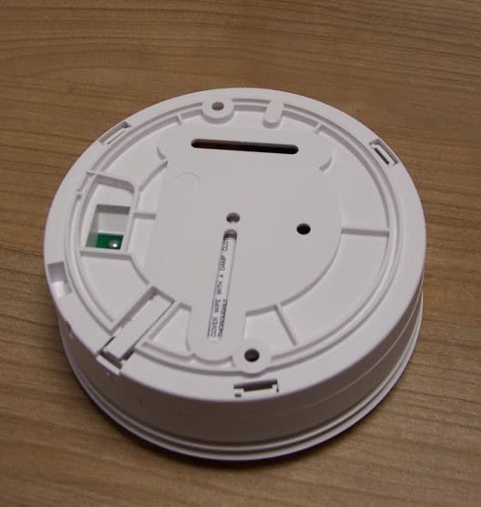
G2X-646041E
May 14, 2013312 Ei Smoke Alarm Model 64604/14
Equipment Class
DSC - Part 15 Security/Remote Control Transmitter
G2X-66004V
Dec 17, 201266004/09 iVi Personal Fall Detector.
Equipment Class
DXX - Part 15 Low Power Communication Device Transmitter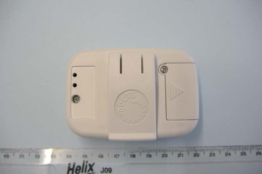
G2X66004
Jan 29, 2008312 Fall Detector
Equipment Class
DSC - Part 15 Security/Remote Control Transmitter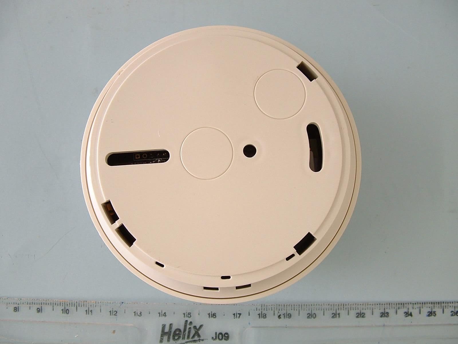
G2X-6460474A
Dec 15, 2006Radio Smoke Detector model 64604/74
Equipment Class
DSC - Part 15 Security/Remote Control Transmitter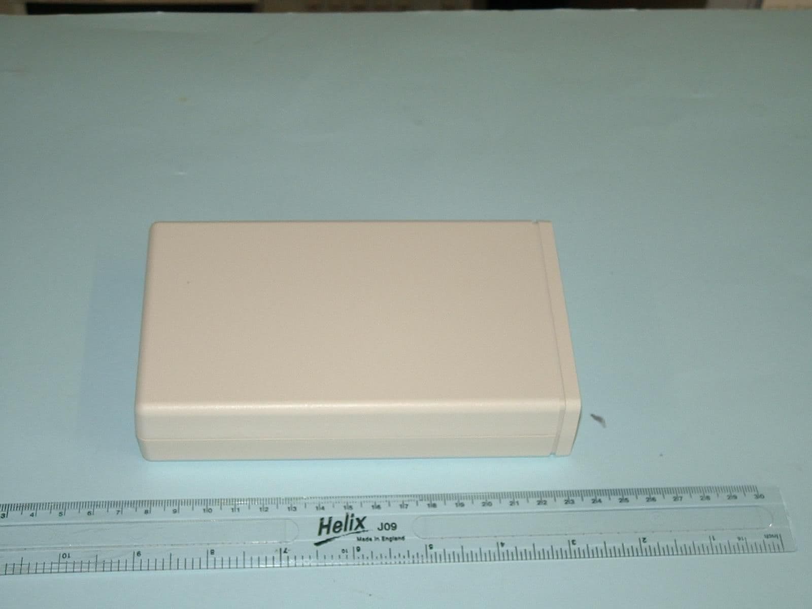
G2X-41004A
Jun 12, 2006Telecare Interface Module type 41004A
Equipment Class
DSC - Part 15 Security/Remote Control Transmitter