G2X-646041E312 Ei Smoke Alarm Model 64604/14
Tunstall Healthcare (UK) Limited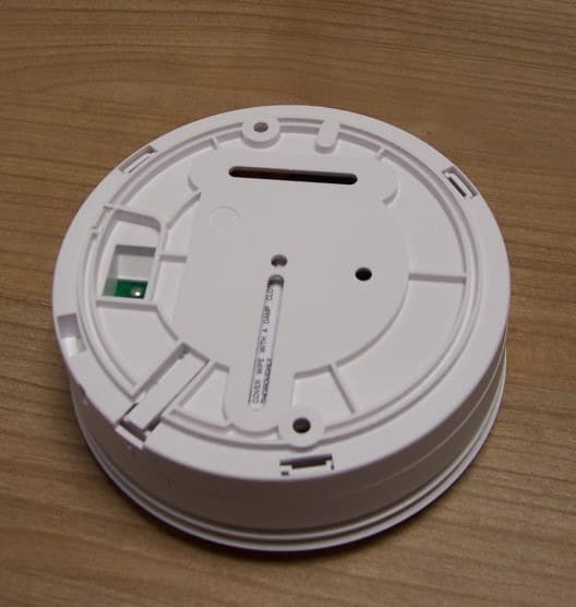
Click to zoom
Application Details
- Equipment Class
- DSC - Part 15 Security/Remote Control Transmitter
- Date of Grant
- May 14, 2013
- Application Purpose
- Original Equipment
- Date of Application
- May 14, 2013
- Equipment Note
- 312 Ei Smoke Alarm Model 64604/14
- Frequency Range
- 312.00000000 - 312.00000000
- Country
- United Kingdom
Documents & Files
Document Text
Text extracted from the exhibit documents filed with the FCC. Open a document above to read the original.
Users Manual
Read and retain for as long as the product is being used. It contains vital information on the operation and installation of your Alarm. The leaflet should be regarded as part of the product. If you are just installing the unit, the leaflet must be given to the householder. The leaflet is to be given to any subsequent user. EiA605 Smoke Alarm SeriesEiA603 Heat Alarm Series Instructions Battery Powered Smoke & Heat Alarms EiA600 Series 2 Page CONTENTS 1 2 3 4 5 6 7 8 9 10 11 12 Quick Start Guide ..................................................................................... Location & Positioning ........................................................................... Installation ................................................................................................. Testing, Maintenance & Power Supply Monitoring ..................... Fire Safety Advice .................................................................................. Smoke Alarm Limitations ..................................................................... Radiolink Accessories ............................................................................. Getting Your Alarm Serviced ............................................................... Five Year Guarantee ................................................................................ Troubleshooting ........................................................................................ Technical Specifications ......................................................................... Contact Us .................................................................................................. 4 7 15 19 24 27 28 29 29 31 32 35 Model EiA605 Note: Certain alarms may be supplied (on request) with the appropriate RF module fitted None None EiA605MRF EiA605MRF Optional RF Module Model No. 9V Replaceable Battery Table 1 EiA605W EiA603W Optical Optical Heat Alarm Type No No No Hardwired Interconnect No No Yes EiA603 Heat No Yes RF Capability Supplied 3 4 1. Quick Start Guide LOCATE CORRECT SITING POINTFIX BASEPLATE TO CEILING CONNECT BATTERY SNAPS 9V BATTERY MODELS ONLY Quick Start Guide PLACE ALARM & TWIST ON TO BASE TEST ALARM ALARM SHOULD BE CEILING MOUNTED AT LEAST 300MM FROM WALLS & OBSTRUCTIONS, IDEALLY CENTRALLY IN ROOM/AREA CONNECT THE BATTERY TO THE BATTERY SNAPS TO POWER THE UNIT TEST ALARM AT LEAST WEEKLY PRESS THE TEST BUTTON BASE OF ALARM 9 VOLT BATTERY BATTERY CONNECTORS 1. Quick Start Guide LOCATE CORRECT SITING POINTFIX BASEPLATE TO CEILING CONNECT BATTERY SNAPS9V BATTERY MODELS ONLY Quick Start Guide PLACE ALARM & TWIST ON TO BASE TEST ALARM ALARM SHOULD BE CEILING MOUNTED AT LEAST 300MM FROM WALLS & OBSTRUCTIONS, IDEALLY CENTRALLY IN ROOM/AREA CONNECT THE BATTERY TO THE BATTERY SNAPS TO POWER THE UNIT TEST ALARM AT LEAST WEEKLY PRESS THE TEST BUTTON BASE OF ALARM 9 VOLT BATTERY BATTERY CONNECTORS 5 6 Normal Operation Standby HORN / SOUNDERRED LED Power Up 1 Flash 1 Flash every 45 seconds Off Off Off Off Full sound Ramps to full sound Full sound Rapid Flashing (every 0.5 sec) 1 Flash every 8 secs for 10 mins Rapid Flashing (every 0.5 sec) Sensing Fire Sensing fire through interconnect 1 beep every 45 sec1 Flash every 45 sec Low Battery 1 beep every 45 sec Off Faulty Smoke Sensor Test Smoke alarm (press button) EiA605 INDICATOR SUMMARY Silence Smoke alarm (press button) Fault Mode Test Mode 2. Location & Positioning Introduction Congratulations on purchasing an EiA600 Series Alarm. You can easily install these alarms throughout the property on escape routes, on each storey, in corridors & in closed rooms to give warning of fire. The Heat Alarms can be installed in kitchens and other areas where Smoke Alarms are unsuitable. All models (except EiA605 & EiA603) can be interconnected using the RadioLINK plug-in modules (These modules must be purchased separately when they are not supplied with the Alarm (see Table 1)). Note: Certain alarms may be supplied (on request) with the appropriate RF module fitted. NATIONAL FIRE PROTECTION ASSOCIATION REQUIRED PROTECTION For your information the National Fire Protection Association’s standard 72 advices as follows: Where required by applicable laws, codes, or standards for specified occupancy, approved single and multiple-station smoke alarms shall be installed as follows: (1) In all sleeping rooms and Guest Rooms (2) Outside of each separate dwelling unit sleeping area, within 6.4M (21ft) of any door to a sleeping room, the distance measured along a path to travel. (3) On each level of the dwelling unit, including the basement. (4) “On every level of a residential board and care occupancy (small facility), including basements and excluding: 7 - crawl spaces and unfinished attics” - “In the living area(s) of a guest suite” - “In the living area(s) of a residential board and care occupancy” “Are More Smoke Detectors Desirable? The required number of smoke detectors might not provide reliable early warning protection for those areas separated by a door for the areas protected by the required smoke detector. For this reason, it is recommended that householder consider the use of additional smoke detectors for those areas or increased protection. The additional areas include the basement, bedrooms, dining room, furnace room, utility room, and hallways not protected by the required smoke detectors. The installation of smoke detectors in kitchens, attics (finished or unfinished), or garages is n ot normally recommended as these locations occasionally experience conditions that can result in improper operation.” The equipment should be installed using wiring methods in accordance with the National Fire Protection Association’s Standard 72, Chapter 11. (National Fire Protection Association, Batterymarch Park, Quincy, MA 02269). IMPORTANT! Specific requirements for Smoke Alarm installation vary from state to state and from region to region. Check with your local Fire Department for current requirements i…
Text truncated - open the document above for the full version.
Users Manual
D6407140A Tunstall Approval Statements Federal Communications Commission (FCC) notices 312 Ei Smoke Alarm (Model: 64604/14) FCC ID: G2X-646041E This Device complies with Part 15 of the FCC Rules. Operation is subject to the following two conditions: (1) This device may not cause harmful interference, and (2) This device must accept any interference received, including interference that may cause undesired operation. This equipment complies with FCC radiation exposure limits set forth for an uncontrolled environment. End users must follow the specific operating instructions for satisfying RF exposure compliance. This transmitter must not be co-located or operating in conjunction with any other antenna or transmitter. Changes or modifications to this unit not expressly approved by the party responsible for compliance could void the user’s authority to operate the equipment. Industry Canada Notices 312 Ei Smoke Alarm (Model: 64604/15) IC: 1231A-646041E Under Industry Canada regulations, this radio transmitter may only operate using an antenna of a type and maximum (or lesser) gain approved for the transmitter by Industry Canada. To reduce potential radio interference to other users, the antenna type and its gain should be so chosen that the equivalent isotropically radiated power (e.i.r.p.) is not more than that necessary for successful communication. This device complies with Industry Canada licence-exempt RSS standard(s). Operation is subject to the following two conditions: (1) this device may not cause interference, and (2) this device must accept any interference, including interference that may cause undesired operation of the device. D6407140A Conformément à la réglementation d'Industrie Canada, le présent émetteur radio peut fonctionner avec une antenne d'un type et d'un gain maximal (ou inférieur) approuvé pour l'émetteur par Industrie Canada. Dans le but de réduire les risques de brouillage radioélectrique à l'intention des autres utilisateurs, il faut choisir le type d'antenne et son gain de sorte que la puissance isotrope rayonnée équivalente (p.i.r.e.) ne dépasse pas l'intensité nécessaire à l'établissement d'une communication satisfaisante. Le présent appareil est conforme aux CNR d'Industrie Canada applicables aux appareils radio exempts de licence. L'exploitation est autorisée aux deux conditions suivantes : (1) l'appareil ne doit pas produire de brouillage, et (2) l'utilisateur de l'appareil doit accepter tout brouillage radioélectrique subi, même si le brouillage est susceptible d'en compromettre le fonctionnement. Service The product contains no user serviceable parts. Tunstall service contact details: Tunstall Americas, 2252 Pearl Buck Road, Unit F, Bristol PA, 19007. Tel: 1-877-903-5111 Tunstall Canada, 7540 Bath Road, Mississauga, Ontario, L4T 1L2, Canada.
ID Label/Location Info
Radio transmitter label 20mm x 13mm
ID Label/Location Info
P/N A17465 Rev0 Made in Ireland for Tunstall Americas Model: 64604/14 EiA605W ALARM GUIDE: Alarm Low battery Sensitivity = = = Continuous horn 1 beep 1 flash every 40 sec 0.9% - 1.8% OBS / Ft Single and / or Multiple Station Smoke Alarm For repair or service return to: Tunstall Americas: 2522 Pearl Buck Road, Bristol PA 19007 USE ONLY BATTERIES SPECIFIED, THE USE OF OTHER BATTERIES MAY HAVE A DETRIMENTAL EFFECT ON ALARM OPERATION. CONSTANT USE AT HIGH OR LOW TEMPERATURE OR HIGH HUMIDITY MAY REDUCE BATTERY LIFE. IMPORTANT! - TEST THIS ALARM ONCE A WEEK - GENTLY VACUUM TO REMOVE ACCUMULATED DUST & COBWEBS MONTHLY. TO CLEAN THE COVER WIPE WITH A DAMP CLOTH & DRY THOROUGHLY. WARNING! US Cut Form
ID Label/Location Info
NO BATTERY PAS DE PILE P/N A17467 Rev0 38mm x 16mm Please read user manual – Lisez attentivement le mode dʼemploi. Use only / Utilisez seulement: Duracell MN1604
Test Report
Radio Test report FOR Tunstall Healthcare (UK) Ltd. ON 312MHz Ei UL Smoke Alarm DOCUMENT NO. TRA-012941-W-US-01 Total number of pages : 54 TRaC Radio Test Report : TRA-012941-W-US-01 Applicant : Tunstall Healthcare (UK) Ltd. Apparatus : 312MHz Ei UL Smoke Alarm FCC ID : G2X-646041E IC ID : 1231A-646041E Authorised by : :Radio Product Manager Issue Date : 13 th May 2013 Authorised Copy Number : PDF Radio Test Report TRA-012941-W-US-01 3 Contents Section 1: Introduction 4 1.1 General 4 1.2 Tests Requested By 5 1.3 Manufacturer 5 1.4 Apparatus Assessed 5 1.5 Results Test Summary 6 1.6 Notes relating to the assessment 8 1.7 Deviations from Test Standards 8 Section 2: Measurement Uncertainty 9 2.1 Measurement Uncertainty Values 9 Section 3: Modifications 10 3.1 Modifications Performed During Assessment 10 Appendix A: Formal Emission Test Results 11 A1 Radiated Fundamental Carrier Power 12 A2 Radiated Electric Field Emissions 15.231(b), general limits 15.209 and 15.205 Restricted Band 15 A3 20 dB Bandwidth 19 A4 Manual Operated Transmitter 20 A5 Automatically Activated Transmitter 21 A6 ac Power Line Conducted Emissions 15.207 22 A7 Unintentional Radiated Electric Field Emissions - 15.109 23 A8 ac Power Line Conducted Emissions 15.107 24 A9 99% Occupied Bandwidth 25 Appendix B: Supporting Graphical Data 26 Appendix C: Additional Test and Sample Details 34 Appendix D: Additional Information 40 Appendix E: Calculation of the duty cycle correction factor 41 Appendix F: Photographs and Figures 43 Appendix G: MPE Calculation 51 Appendix H: FCC CFR47 Part 15(c) / IC RSS-210 Comparison Table 53 Radio Test Report TRA-012941-W-US-01 4 Section 1: Introduction 1.1 General This report contains an a ssessment of an apparatus against Electromagnetic Compatibility Standards based upon tests carried out on samples submitted to the Laboratory. Test performed at: TRaC Global [ X ] Unit E South Orbital Trading Park Hedon Road Hull, HU9 1NJ. United Kingdom. Telephone: +44 (0) 1482 801801 Fax: +44 (0) 1482 801806 TRaC Global [] Unit 1 Pendle Place Skelmersdale West Lancashire, WN8 9PN United Kingdom Telephone: +44 (0) 1695 556666 Fax: +44 (0) 1695 577077 Email: [email protected] Web site: http://www.tracglobal.com Tests performed by: M E Leach Report author: As Above This report must not be reproduced except in full without prior written permission from TRaC Global Ltd Radio Test Report TRA-012941-W-US-01 5 1.2 Tests Requested By This testing in this report was requested by : Tunstall Healthcare (UK) Ltd Whitley Lodge Whitley Bridge Yorkshire DN14 0HR 1.3 Manufacturer As Above 1.4 Apparatus Assessed The followin g apparatus was assessed between: 19/02/13 to 21/02/13 312MHz Ei UL Smoke Alarm The above equipment was a battery powered smoke alarm that combined a 312MHz transmitter. Radio Test Report TRA-012941-W-US-01 6 1.5 Results Test Summary Full details of test results are contained within Appendix A. The following table summarises the results of the assessment. The statements relating to compliance with the standards below apply ONLY as qualified in the notes and deviations stated in sections 1.6 to 1.7 of this test report. Full details of test results are contained within Appendix A. The following table summarises the results of the assessment. Test Type Regulation Measurement standard Result Radiated Carrier Power Title 47 of the CFR: Part 15 Subpart (c) 15.231(b) ANSI C63.10:2009 Pass Radiated spurious emissions (None and Restricted bands) Title 47 of the CFR: Part 15 Subpart (c) 15.231(b), 15.205 and 15.209 ANSI C63.10:2009 Pass Emission Bandwidth Title 47 of the CFR : Part 15 Subpart (c) 15.231(c) ANSI C63.10:2009 Pass Manual Operated Transmitter Title 47 of the CFR : Part 15 Subpart (c) 15.231(a)(1) - Pass Automatically Activated Title 47 of the CFR : Part 15 Subpart (c) 15.231(a)(2) - Pass AC Power conducted Emissions Title 47 of the CFR: Part 15 Subpart (c) 15.207 ANSI C63.10:2009 N/A Unintentional Radiated Spurious Emissions Title 47 of the CFR: Part 15 Subpart (b) 15.109 ANSI C63.4:2009 Pass AC Power conducted Emissions Title 47 of the CFR: Part 15 Subpart (b) 15.107 ANSI C63.4:2009 N/A Bandwidth of Momentary Signals (99% OBW) RSS-210 Issue 8 December 2010 RSS-Gen 4.6.1 Issue 3 December 2010 RSS-210 Issue 8 December 2010: A1.1.3 N/A Radio Test Report TRA-012941-W-US-01 7 Abbreviations used in the above table: ANSI C 63.10:2009 is outside the scope of the laboratories UKAS accreditation. Mod : Modification ANSI : American National Standards Institution CFR : Code of Federal Regulations PLCE : Power Line Conducted Emissions REFE : Radiated Electric Field Emissions N/A Not Applicable Radio Test Report TRA-012941-W-US-01 8 1.6 Notes relating to the assessment With regard to this assessment, the following points should be noted: The results contained in this report relate only to the items tested and were obtained in the period between the date of initial receipt of samples and the date of issue of the report. The apparatus was set up and exercised using the configurations, modes of operation and arrangements defined in this report only. Particular operating modes, apparatus monitoring methods and performance criteria required by the standards tested to have been performed except where identified in Section 1.7 of this test report (Deviations from Test Standards). For emissions testing, throughout this test report, “Pass” indicates that the results for the sample as tested were below the specified limit (refer also to Section 2, Measurement Uncertainty). Where relevant, the apparatus was only assessed using the monitoring methods and susceptibility criteria defined in this report. All testing with the exception of testing at the Open Area Test Site was performed under the following environmental conditions: Temperature : 17 to 23 C Humidity : 45 to 75 % Barometric Pressure : 86 to 106 kPa All dates used in this report are in the format dd/mm/yy. This assessment has been performed in accordance with the r…
Text truncated - open the document above for the full version.
Contact Information
Applicant
Mark Jennings(Chief Engineer)
Test Firm
Element Materials Technology Warwick LtdMax Leach
Technical Specifications
| # | Rule Parts | Frequency Range | Power Output |
|---|---|---|---|
| 1 | 15.231 | 312 MHz - 312 MHz | - |
Other Applications from Tunstall Healthcare (UK) Limited

G2X-66004V
Dec 17, 201266004/09 iVi Personal Fall Detector.
Equipment Class
DXX - Part 15 Low Power Communication Device Transmitter
G2X-6360412
Dec 06, 201263604/12 Amie Personal Fall Alarm
Equipment Class
DXX - Part 15 Low Power Communication Device Transmitter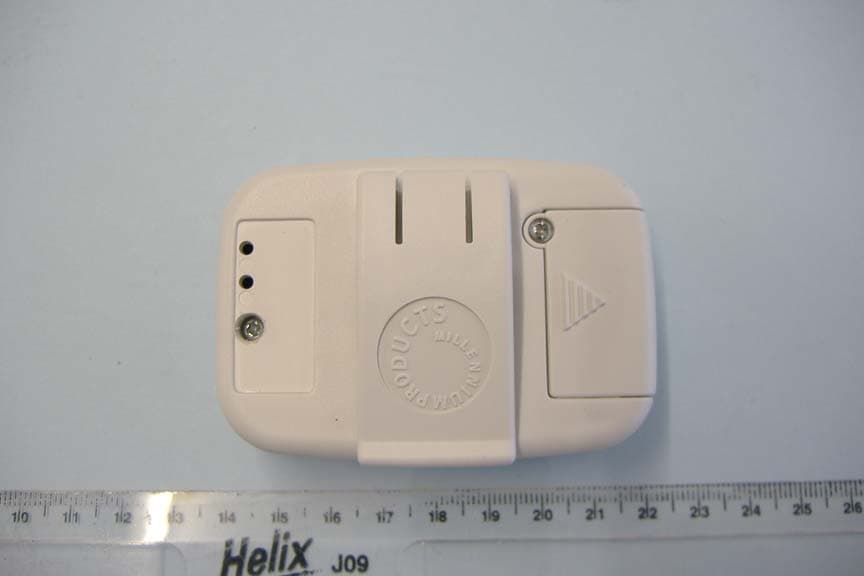
G2X66004
Jan 29, 2008312 Fall Detector
Equipment Class
DSC - Part 15 Security/Remote Control Transmitter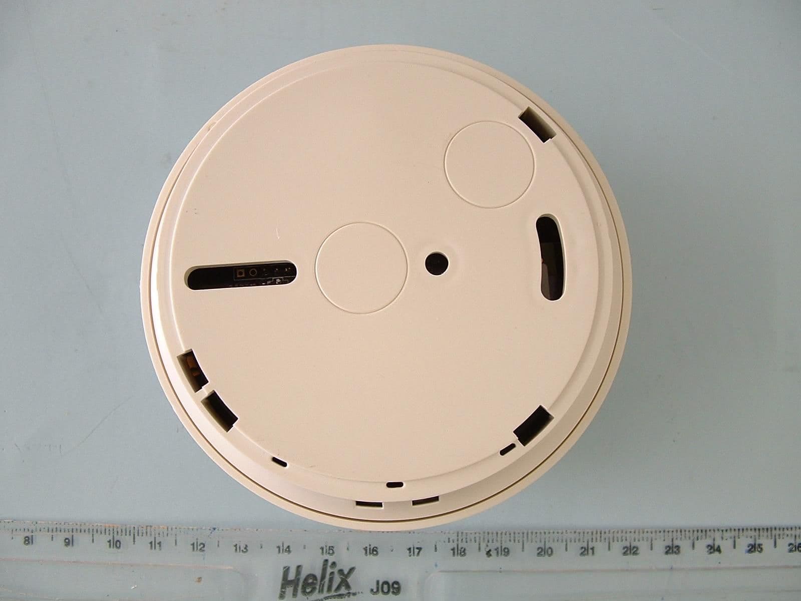
G2X-6460474A
Dec 15, 2006Radio Smoke Detector model 64604/74
Equipment Class
DSC - Part 15 Security/Remote Control Transmitter
G2X-41004A
Jun 12, 2006Telecare Interface Module type 41004A
Equipment Class
DSC - Part 15 Security/Remote Control Transmitter