G2X-66004V66004/09 iVi Personal Fall Detector.
Tunstall Healthcare (UK) Limited
Click to zoom
Application Details
- Equipment Class
- DXX - Part 15 Low Power Communication Device Transmitter
- Date of Grant
- Dec 17, 2012
- Application Purpose
- Original Equipment
- Date of Application
- Dec 17, 2012
- Equipment Note
- 66004/09 iVi Personal Fall Detector.
- Frequency Range
- 312.00000000 - 312.00000000
- Country
- United Kingdom
Documents & Files
Document Text
Text extracted from the exhibit documents filed with the FCC. Open a document above to read the original.
Users Manual
Contents iVi™ ‘the intelligent pendant’ with auto fall detection User Guide Page 2 of 28 What is the iVi? 4 What is in the box? 5 Before first use 6 Wearing the fall detector... 7 ... on a neck cord............................................... 8 ... as a brooch/clipped to clothing ................... 10 ... on a belt ...................................................... 10 Important things to remember 11 How it works 11 Manual alarm operation 12 What happens if you fall .................................. 13 Cancelling an automatic fall alarm 14 Care of the fall detector 15 Spares and Accessories 16 Battery Replacement 17 Declaration of Conformity ................................ 23 User Guide Page 3 of 28 This user guide is available in multiple languages please visit tunstall.com/productinfo Programming Guide A separate programming guide is also available at tunstall.com/productinfo Page 4 of 28 What is the iVi? Your iVi™ is an intelligent pendant that has all the features of a standard pendant, allowing you to generate an alarm call when you need help. The iVi also provides an added layer of protection by automatically generating a call for assistance if you fall and are unable to push the help button. Status LED Help button Wearing option attachment point Battery cover Cancel button Neck cord attachment point Air vent Page 5 of 28 What is in the box? The box contains this user guide, an iVi ‘intelligent pendant’, belt clip, neck cord and clothing clip. iVi ‘intelligent pendant’ Neck cord* Clothing Clip* Belt clip* *May not be supplied Page 6 of 28 Before first use Ensure the iVi is programmed correctly to your Lifeline home unit. To test this press the help button and ensure that is generates an alarm call to the monitoring centre. Tell the monitoring centre that you are making a test call and then ask them to end the call. It is important to test the iVi in all the areas of your home, including the bathroom, basement and garage, as environmental conditions such as furnishings, building structure, submersion in liquid etc. may affect the range. A help call will NOT be initiated if the iVi is activated whilst out of range of the home unit. Page 7 of 28 Wearing the iVi detector... Your iVi will have been configured for a specific wearing option once setup you should not change the wearing option without contacting your supplier. The correct wearing positions for the different wearing options available are shown on the following pages. Wearing the iVi in line with this guidance is important as it helps to ensure it is in the most optimum position to detect falls whilst also helping to reduce the chance of incorrect activations. Please remember to wear your iVi at all times when you are in or around your home. You may also wear your iVi in bed if required. WARNING – if you wear the iVi under your clothing please ensure you do not restrict access to the help button. Page 8 of 28 ... on a neck cord An adjustable neck cord is provided which should be adjusted to ensure the cord is not too long. The iVi should be fitted so that it sits at the height of your sternum. To avoid having to adjust the length of the cord each time you put the iVi on, pull apart one of the break links on the cord and then push them together again once you have put the cord over your head. Tip - Clipping it to clothing using the brooch/clothing clip whilst worn on a neck cord may also help to reduce false alerts WARNING – only use the neck cord supplied as it includes break links to increase safety. Page 9 of 28 Adjusting the neck cord To shorten, pull the plastic tabs in opposite directions To lengthen, hold the neck cord just below the plastic tabs and pull apart. Taking off/Putting on the iVi To avoid having to adjust the length of the neck cord each time you take off/put on the iVi, you can undo one of the break links on the neckcord, take each side of the neck cord round your neck and then fasten the break link again. Break link Page 10 of 28 ... as a brooch/clipped to clothing The iVi can be worn in either of these orientations in order to clip it to shirt pockets, shirt/blouse openings etc. Tip - The clips are reversible to enable them to be clipped to the left or right for male and female shirt openings. ... on a belt The belt clip is designed to fit a wide variety of belts however you should ensure that the belt is of sufficient width to firmly hold the iVi in place. Page 11 of 28 Important things to remember • Remember, the iVi will only detect you falling if you are wearing it. • The iVi must be worn in accordance with the wearing instructions, do not change the wearing option once your preferred method has been chosen. • Due to the complex dynamics of falling, all falls may not be detected. In the event of a fall you should always try to press the help button on the iVi. • If you fall and cannot press the help button, the iVi will generate a call for assistance within 30 seconds. • Test the iVi at regular intervals by pressing the help button How it works The iVi is designed to be worn as a pendant therefore if you require assistance or if you fall you should always press the help button. Page 12 of 28 If you are unable to press the help button the iVi has intelligent sensors that will automatically generate an alarm. Manual alarm operation • Press the help button on the iVi to generate a call for help. • The red LED indicates the iVi is sending an alarm call. • If the red LED flashes on and off, the iVi is still sending an alarm call, but is also indicating to you that the battery needs to be replaced. Press help button Page 13 of 28 What happens if you fall • Stage 1 – the iVi detects an event and analyses it for up to 20 seconds. If the iVi decides that event is a fall, stage 2 is started. • Stage 2 – The Green LED is turned on and the sounder plays ascending tones. This warns you that a fall alarm is about to be made and provides 10 seconds for you to cancel the alarm. • Stage 3 – if the alarm is no…
Text truncated - open the document above for the full version.
Test Report
A Radio Test Report FOR Tunstall Healthcare (UK) Ltd on 66004/09 Fall Detector DOCUMENT NO. TRA-011638-W-NA-1 Total number of pages: 33 TRaC Wireless Test Report : TRA-0116 38-W-NA-1 Applicant : Tunstall Healthcare (UK) Ltd Apparatus : 66004/09 Fall Detector Specification(s) : CFR47 Part 15 & RSS-210 Purpose of Test : Certification FCCID : G2X-66004V IC Certification Number : 1231A-66004V Authorised by : : Radio Product Manager Issue Date :26 th November 2012 Authorised Copy Number : PDF TRaC Global Test Report: TRA-011638-W-NA-1 Contents Section 1: Introduction 4 1.1 General 4 1.2 Tests Requested By 5 1.3 Manufacturer 5 1.4 Apparatus Assessed 5 1.5 Test Result Summary 6 1.6 Notes Relating To The Assessment 7 1.7 Deviations from Test Standards 7 Section 2: Measurement Uncertainty 8 2.1 Measurement Uncertainty Values 8 Section 3: Modifications 10 3.1 Modifications Performed During Assessment 10 Appendix A: Formal Emission Test Results 11 A1 Transmitter Intentional Emission Radiated 12 A2 Radiated Electric Field Emissions 14 Appendix B: Supporting Graphical Data 16 Appendix C: Additional Test and Sample Details 21 C1) Test samples 22 C2) EUT Operating Mode During Testing. 23 C3) EUT Configuration Information. 24 C4) List of EUT Ports 25 C5) Details of Equipment Used 26 Appendix D: Additional Information 27 Appendix E: Calculation of the duty cycle correction factor 28 Appendix F: Photographs and Figures 29 Appendix G: MPE Calculation 32 3 TRaC Global Test Report: TRA-011638-W-NA-1 Section 1: Introduction 1.1 General This report contains an assessment of an apparatus against Electromagnetic Compatibility Standards based upon tests carried out on samples submitted to the Laboratory. Test performed by: TRaC Global [ ] Unit E South Orbital Trading Park Hedon Road Hull, HU9 1NJ. United Kingdom. Telephone: +44 (0) 1482 801801 Fax: +44 (0) 1482 801806 TRaC Global [X] Unit 1 Pendle Place Skelmersdale West Lancashire, WN8 9PN United Kingdom Telephone: +44 (0) 1695 556666 Fax: +44 (0) 1695 577077 Email: [email protected] Web site: http://www.tracglobal.com Tests performed by: D Winstanley Report author: D Winstanley This report must not be reproduced except in full without prior written permission from TRaC Global. 4 TRaC Global Test Report: TRA-011638-W-NA-1 1.2 Tests Requested By This testing in this report was requested by : Tunstall Healthcare (UK) Ltd Whitley Lodge Whitley Bridge Yorkshire DN14 0HR 1.3 Manufacturer As Above 1.4 Apparatus Assessed The followin g apparatus was assessed between 20 th October and 19 th November 66004/09 Fall Detector The above equipment was a 312MHz transmitter. 5 TRaC Global Test Report: TRA-011638-W-NA-1 1.5 Test Result Summary Full details of test results are contained within Appendix A. The following table summarises the results of the assessment. The statements relating to compliance with the standards below apply ONLY as qualified in the notes and deviations stated in sections 1.6 to 1.7 of this test report. Full details of test results are contained within Appendix A. The following table summarises the results of the assessment. Regulation Test Type RSS-210 Issue 8 December 2010 Title 47 of the CFR: Part 15 Subpart (c) Measurement standard Result Spurious Emissions Radiated <1000MHz A1.1.2 RSS-Gen 7.2.5 15.231(b) & 15.209 ANSI C63.10:2009 Pass Spurious Emissions Radiated >1000MHz A1.1.2 RSS-Gen 7.2.5 15.231(b) & 15.209 ANSI C63.10:2009 Pass AC Power conducted emissions RSS-GEN Issue 3 Annex 7, 7.2.4 15.207 ANSI C63.10:2009 N/A Transmission times A.1.1.1 15.231(a) ANSI C63.10:2009 Pass Intentional Emission Frequency A1.1.2 RSS-Gen 7.2.5 15.231(b) ANSI C63.10:2009 Pass Intentional Emission Field Strength A1.1.2 RSS-Gen 7.2.5 15.231(b) ANSI C63.10:2009 Pass Intentional Emission Band Occupancy A1.1.3 RSS-Gen 4.6.1 15.215 ANSI C63.10:2009 Pass Intentional Emission ERP (mW) N/A N/A ANSI C63.10:2009 N/A Unintentional Radiated Spurious Emissions RSS-GEN Issue 3 7.2.2(c) 15.109 ANSI C63.10:2009 N/A Antenna Arrangements Integral: RSS-Gen 7.1.2 15.203 - Pass Antenna Arrangements External Connector RSS-Gen 7.1.2 15.204 - N/A Restricted Bands RSS-Gen 7.2.2 15.205 - Pass Maximum Frequency of Search RSS-Gen 4.3 15.33 - Pass Extrapolation Factor RSS-Gen 7.2.7 15.31(f) - Pass Abbreviations used in the above table: ANSI C 63.10:2009 is outside the scope of the laboratories UKAS accreditation. CFR : Code of Federal Regulations ANSI : American National Standards Institution REFE : Radiated Electric Field Emissions PLCE : Power Line Conducted Emissions 6 TRaC Global Test Report: TRA-011638-W-NA-1 1.6 Notes Relating To The Assessment With regard to this assessment, the following points should be noted: The results contained in this report relate only to the items tested and were obtained in the period between the date of initial receipt of samples and the date of issue of the report. The apparatus was set up and exercised using the configurations, modes of operation and arrangements defined in this report only. Particular operating modes, apparatus monitoring methods and performance criteria required by the standards tested to have been performed except where identified in Section 1.7 of this test report (Deviations from Test Standards). For emissions testing, throughout this test report, “Pass” indicates that the results for the sample as tested were below the specified limit (refer also to Section 2, Measurement Uncertainty). Where relevant, the apparatus was only assessed using the monitoring methods and susceptibility criteria defined in this report. All testing with the exception of testing at the Open Area Test Site was performed under the following environmental conditions: Temperature : 17 to 23 C Humidity : 45 to 75 % Barometric Pressure : 86 to 106 kPa All dates used in this report are in the format dd/mm/yy. This assessment has been performed in accordance with the requirements of ISO/IEC 17025. 1.7 Deviations from Test Standards There were no deviations from the st…
Text truncated - open the document above for the full version.
Contact Information
Applicant
Mark Jennings(Chief Engineer)
Test Firm
Element Materials Technology Warwick LtdStewart Barrowclough
Technical Specifications
| # | Rule Parts | Frequency Range | Power Output |
|---|---|---|---|
| 1 | 15C | 312 MHz - 312 MHz | - |
Other Applications from Tunstall Healthcare (UK) Limited
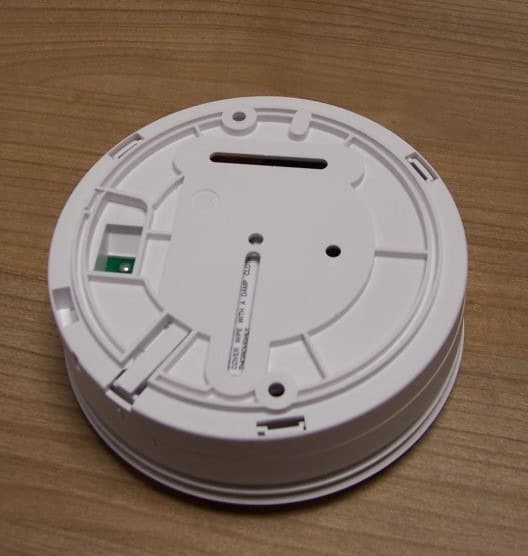
G2X-646041E
May 14, 2013312 Ei Smoke Alarm Model 64604/14
Equipment Class
DSC - Part 15 Security/Remote Control Transmitter
G2X-6360412
Dec 06, 201263604/12 Amie Personal Fall Alarm
Equipment Class
DXX - Part 15 Low Power Communication Device Transmitter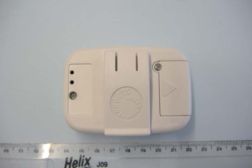
G2X66004
Jan 29, 2008312 Fall Detector
Equipment Class
DSC - Part 15 Security/Remote Control Transmitter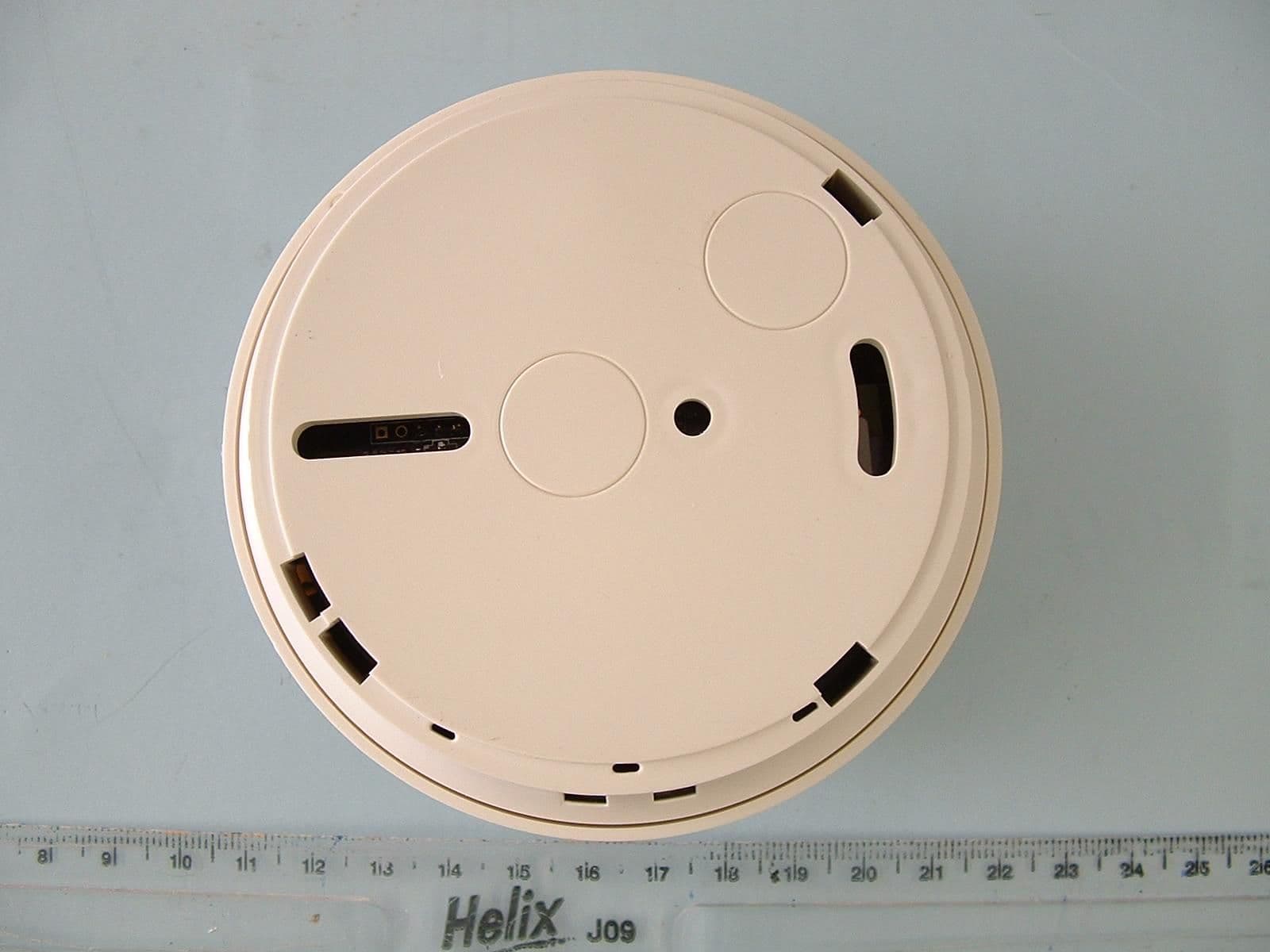
G2X-6460474A
Dec 15, 2006Radio Smoke Detector model 64604/74
Equipment Class
DSC - Part 15 Security/Remote Control Transmitter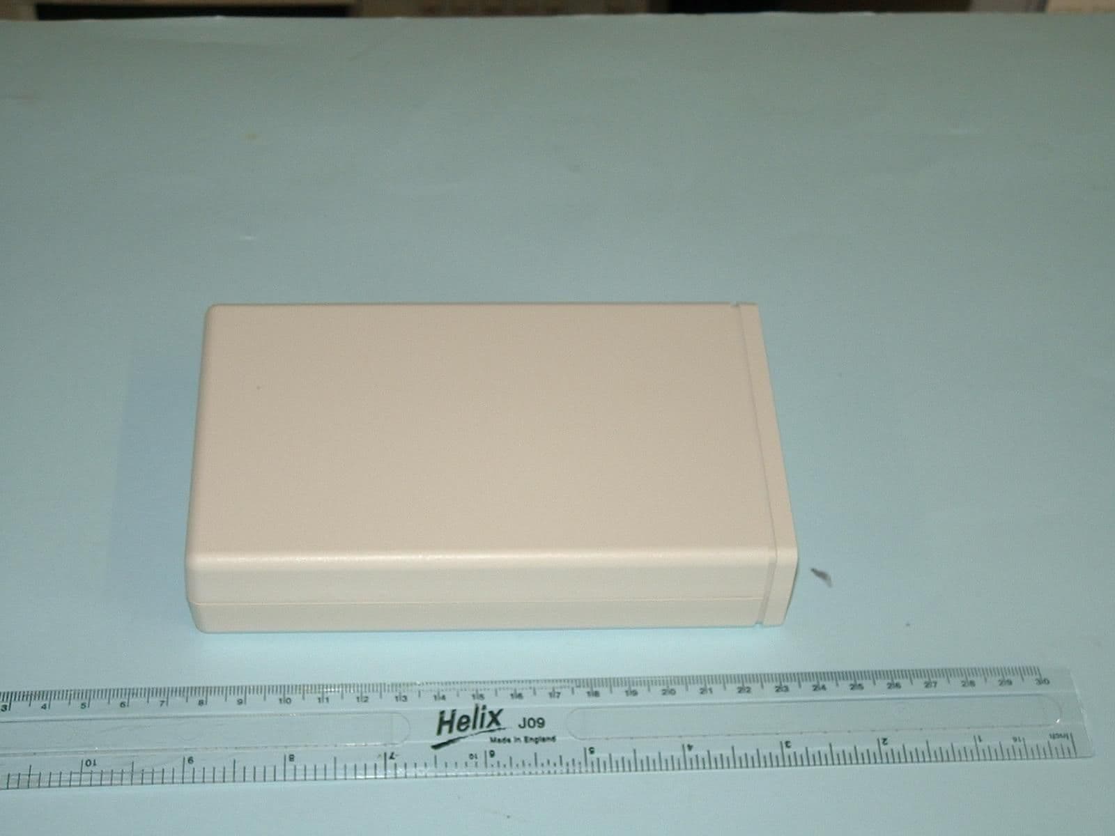
G2X-41004A
Jun 12, 2006Telecare Interface Module type 41004A
Equipment Class
DSC - Part 15 Security/Remote Control Transmitter