G2X-63004Amie Radio Trigger
Tunstall Healthcare (UK) Limited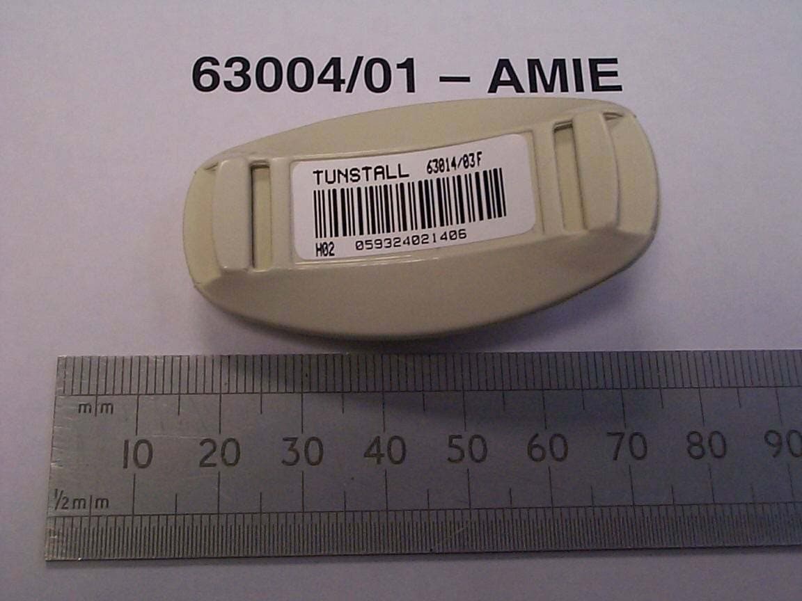
Click to zoom
Application Details
- Equipment Class
- DSC - Part 15 Security/Remote Control Transmitter
- Date of Grant
- Jan 08, 2003
- Application Purpose
- Original Equipment
- Date of Application
- Jan 08, 2003
- Equipment Note
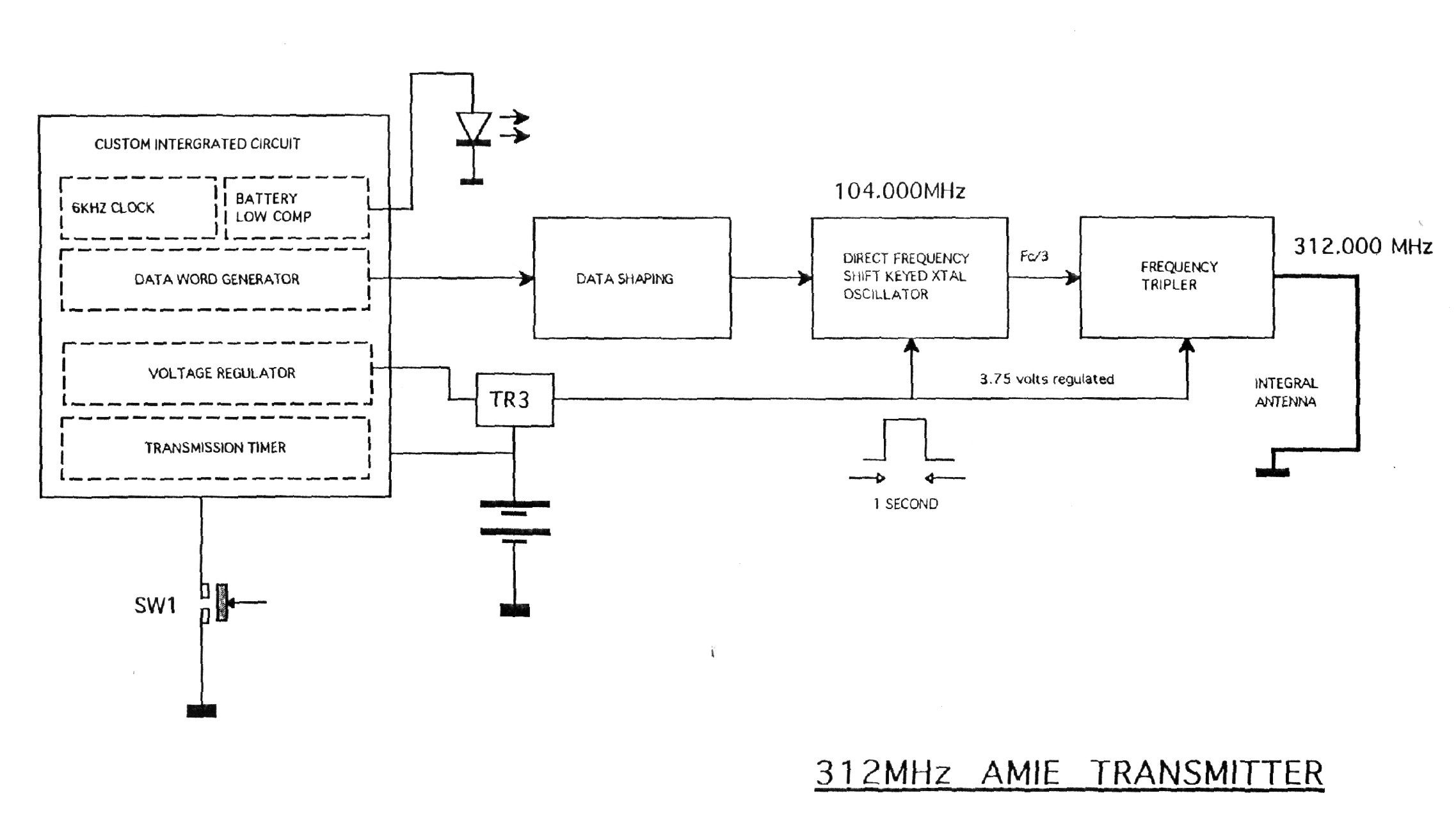
- Amie Radio Trigger
- Frequency Range
- 312.00000000 - 312.00000000
- Country
- United Kingdom
Documents & Files
Document Text
Text extracted from the exhibit documents filed with the FCC. Open a document above to read the original.
Users Manual
Telecom 4000 User Guide All the reassurance you need Part Number D3607104A Tunstall Canada Inc, 7540 Bath Road, Mississauga, Ontario, L4T 1L2, Canada. Tel. 905-677-1144 • Fax. 905-677-1121 • http://www.tunstallcanada.com/ Tel. 1-800-892-2205 Contents Setting up1 Place Telecom 40001 Connect Telecom 40002 Test Telecom 40003 Using Telecom 40004 Requesting help4 Answering a call5 Making a call6 Adjusting the volume7 The Away feature8 The Intruder Alarm9 Using Away and Intruder together11 Using medication reminders12 Using radio pendants13 How close do I have to be to use my radio pendant?14 Amie15 Fall Detector16 Telecom 4000 in detail19 Understanding alarm calls22 Reliability23 Configuring Telecom25 Fast Dial Keys25 Voice Announcements27 Problems and Answers29 Copyright © 2002 Tunstall Group Ltd. All rights reserved. Neither the paper-based guide, nor the electronic version of the same, nor any portion of the text and/or images, may be copied, distributed, broadcast, or transmitted in any form or using any means howsoever, without the express written permis- sion of Tunstall Group Ltd., with the one exception described below. Under no circumstances may the paper-based or electronic guide be edited, amended or adapted, or used for any purpose other than as an aid to using Telecom 4000. Reproducing manuals for visually-impaired users This manual can be copied and enlarged to help visually-impaired users. Such copies may only be given to owners and users of Telecom 4000, and this is the only purpose for which anyone outside Tunstall may reproduce this manual. You may enlarge this manual using a photocopier. Alternatively, you can obtain these manuals as Adobe Acrobat documents (also called PDF files) and print in an enlarged format using the free Adobe Acrobat Reader. You can download these PDF files from the Tunstall web site: http://www.tunstallgroup.com/docs/ You can obtain copies of Adobe Acrobat Reader from Adobe's web site: http://www.adobe.com/ To enlarge a manual while printing with Adobe Acrobat select the 'Fit to Page' option when printing. Trade Marks TM TUNSTALL, AMIE, PNC3 VISION, PNC4 VISION, and TELECOM 4000 are trademarks of the Tunstall Group Limited. © 2002 Tunstall Group Ltd.Telecom 4000 User Guide1 Setting up Three simple steps 1.Place Telecom™ in a suitable position 2.Connect Telecom to your telephone line and a power receptacle 3.Test Telecom by pressing the radio pendant to raise an alarm Although Telecom is a rather clever piece of equipment, it is quite robust, and you can treat it just like any other telephone. However, this means that you should not: •Place your Telecom next to something that makes a lot of noise, such as next to a television, radio or washing machine. •Put it right next to your stove, or close to any other heat source. •Set Telecom in a place where it will get damp, such as a bathroom, or near house plants that are sprayed at any time. • Place it very close to any large metal objects, such as microwave ovens, as large pieces of metal stop the signals from the radio pendant reaching Telecom. •Put Telecom on top of something soft, such as a thick towel, as this can stop sound reaching the microphone. Place Telecom 4000 Place Telecom on a flat surface, or have it mounted on a wall. Put it somewhere you can easily reach. It should also be close to a telephone jack and a power receptacle. Attaching to a wall. If you decide to attach your Telecom to a wall then you will find slots to grip the screws on the back of Telecom. There is a separate paper template included in the packaging that will show you where to drill the holes for the screws. Note: As most users do not mount Telecom 4000 on the wall the screws needed for mounting are not provided. 2Telecom 4000 User Guide© 2002 Tunstall Group Ltd. 2. You can then connect your ordinary telephone to Telecom. If you do not connect your other telephones through Telecom, but use a telephone adaptor instead, then Telecom may have difficulty making alarm calls if another telephone is being used for a call. 3. Next, connect the lead from the AC adapter to the back of your Telecom, and then plug the AC adapter into a power receptacle. Connect Telecom 4000 1. First, connect your Telecom to a telephone jack in your home using the cable that came in the box with Telecom. Do not connect Telecom to the telephone jack via a telephone adaptor. © 2002 Tunstall Group Ltd.Telecom 4000 User Guide3 4. When you connect your Telecom to the power the largest button on the top of your Telecom should light up. Test Telecom 4000 Once you have connected your Telecom you can test it. Press the button on the Fall Detector or Amie pendant that came with your Telecom, and wait a few seconds. Telecom will call your response center. When your call is answered tell the operator that you are testing your new Telecom—the operator will be pleased to hear from you. Problems? In the unlikely event that something does not work as you expect then consult the Problems and Answers section towards the back of this guide. 4Telecom 4000 User Guide© 2002 Tunstall Group Ltd. Using Telecom 4000 Requesting help If you need help simply press the button on your Fall Detector or radio pendant. This sends a signal to Telecom which tells it to call your response center. Alternatively, if you can easily reach your Telecom you can press the large alarm button. Your home can also be fitted with extra buttons and pull cords that raise an alarm. The person who installs these in your home will show you where they are and how they work. Cancelling If you accidentally raise an alarm call (i.e. you unintentionally press one of the alarm buttons on your Telecom or radio pendant) you can cancel the alarm call by waiting five seconds and then pressing your Telecom’s Cancel key. However, once the call reaches a response center pressing the Cancel key will have no effect. This is a safety feature. When the operator answers your call simply explain that it was an error—the op…
Text truncated - open the document above for the full version.
Users Manual
AMIE Radio Trigger (Part Number 63004/01) FCC ID: G2X-63004 This Device complies with Part 15 of the FCC Rules. Operation is subject to the following two conditions: (1) This device may not cause harmful interference, and (2) This device must accept any interference received, including interference that may cause undesired operation. Warning: Changes or modifications to this unit not expressly approved by the party responsible for compliance could void the user's authority to operate the equipment. AMIE Radio Trigger (Part Number 63004/01) FCC ID: G2X-63004 This Device complies with Part 15 of the FCC Rules. Operation is subject to the following two conditions: (1) This device may not cause harmful interference, and (2) This device must accept any interference received, including interference that may cause undesired operation. Warning: Changes or modifications to this unit not expressly approved by the party responsible for compliance could void the user's authority to operate the equipment.
External Photos
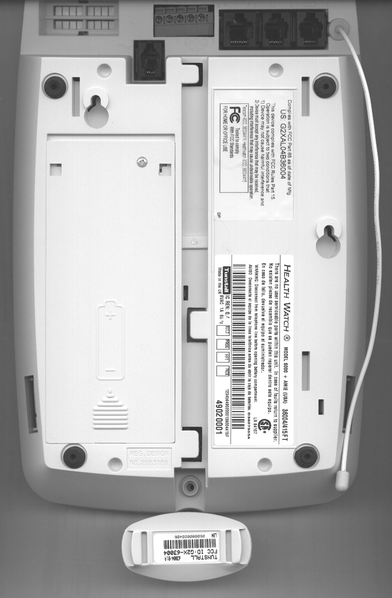
FCC ID: G2X-63004 1(1) Top view Bottom view
Internal Photos
FCC ID: G2X-63004 1(1) Component side Reverse side
Test Report
15.231(a)(1) Manually operated transmitter shall employ a switch that will automatically deactivated the transmitter within not more than 5 seconds of being released
Contact Information
Applicant
Mark Jennings(Chief Engineer)
Technical Contact
Tunstall GroupRichard Nadin
[email protected]44 1977 660398
Whitley Lodge · Whitley Bridge · United Kingdom
Non-Technical Contact
Tunstall GroupRichard Nadin
[email protected]44 1977 660398
Test Firm
Intertek Testing Services NA Inc.Roland Gubisch
Technical Specifications
| # | Rule Parts | Frequency Range | Power Output |
|---|---|---|---|
| 1 | 15.231 | 312 MHz - 312 MHz | - |
Other Applications from Tunstall Healthcare (UK) Limited
G2X-646041E
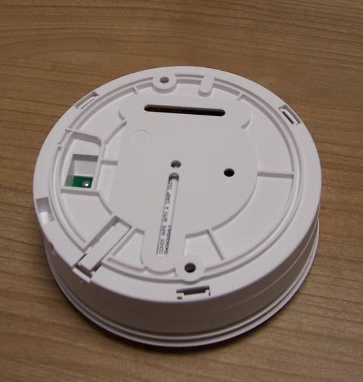
May 14, 2013312 Ei Smoke Alarm Model 64604/14
Equipment Class
DSC - Part 15 Security/Remote Control Transmitter
G2X-66004V
Dec 17, 201266004/09 iVi Personal Fall Detector.
Equipment Class
DXX - Part 15 Low Power Communication Device Transmitter
G2X-6360412
Dec 06, 201263604/12 Amie Personal Fall Alarm
Equipment Class
DXX - Part 15 Low Power Communication Device Transmitter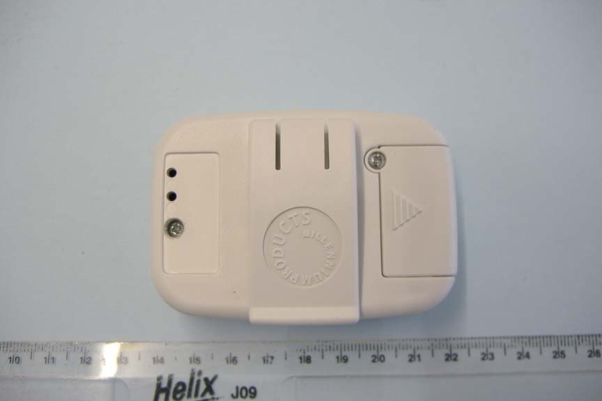
G2X66004
Jan 29, 2008312 Fall Detector
Equipment Class
DSC - Part 15 Security/Remote Control Transmitter
G2X-6460474A
Dec 15, 2006Radio Smoke Detector model 64604/74
Equipment Class
DSC - Part 15 Security/Remote Control Transmitter