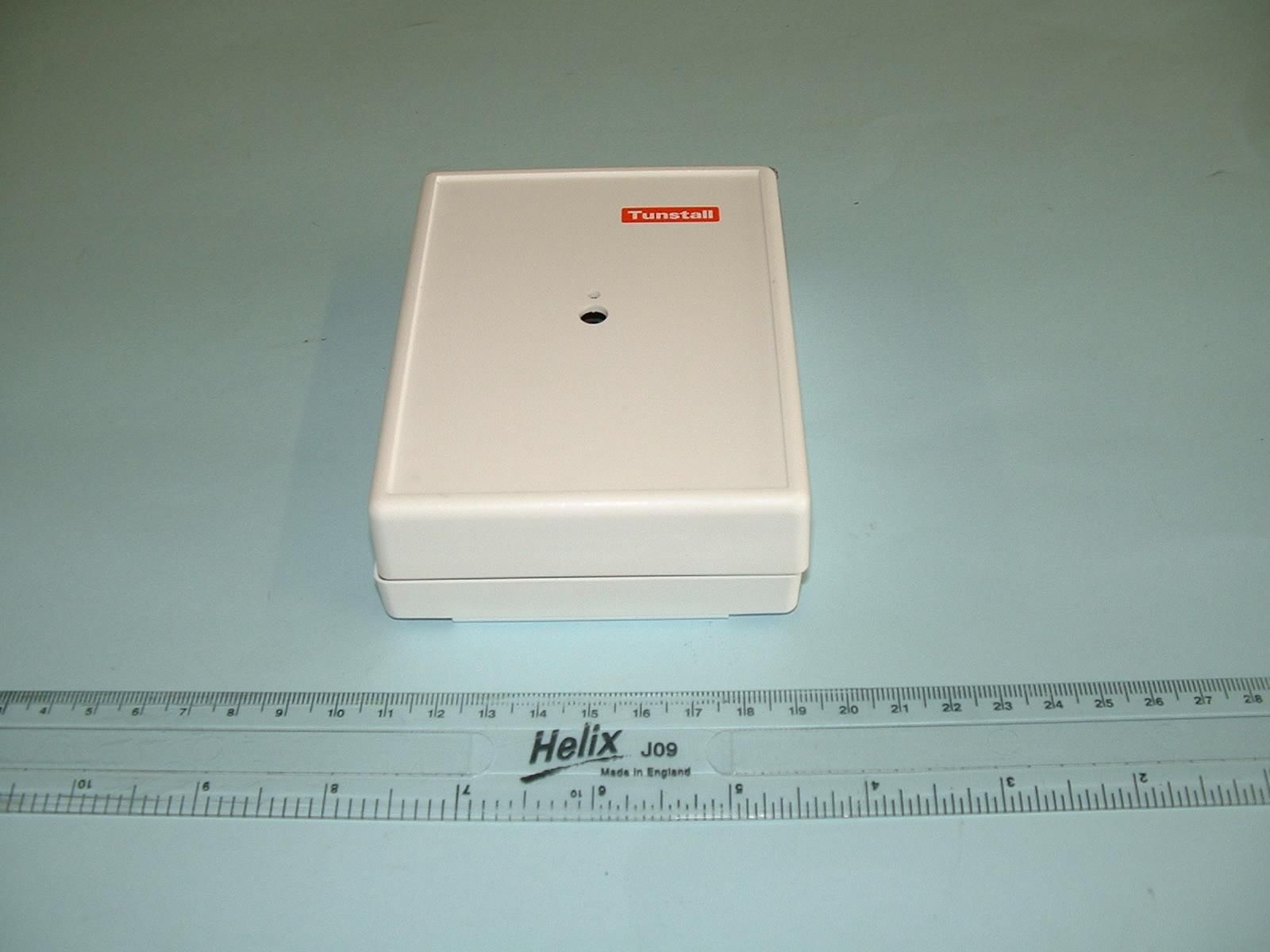
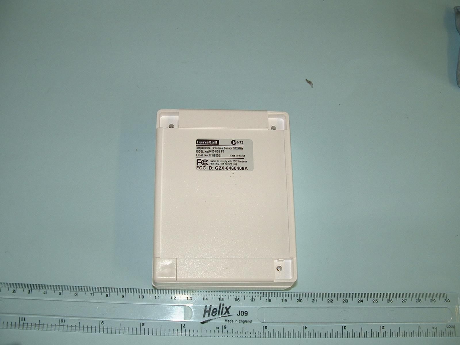
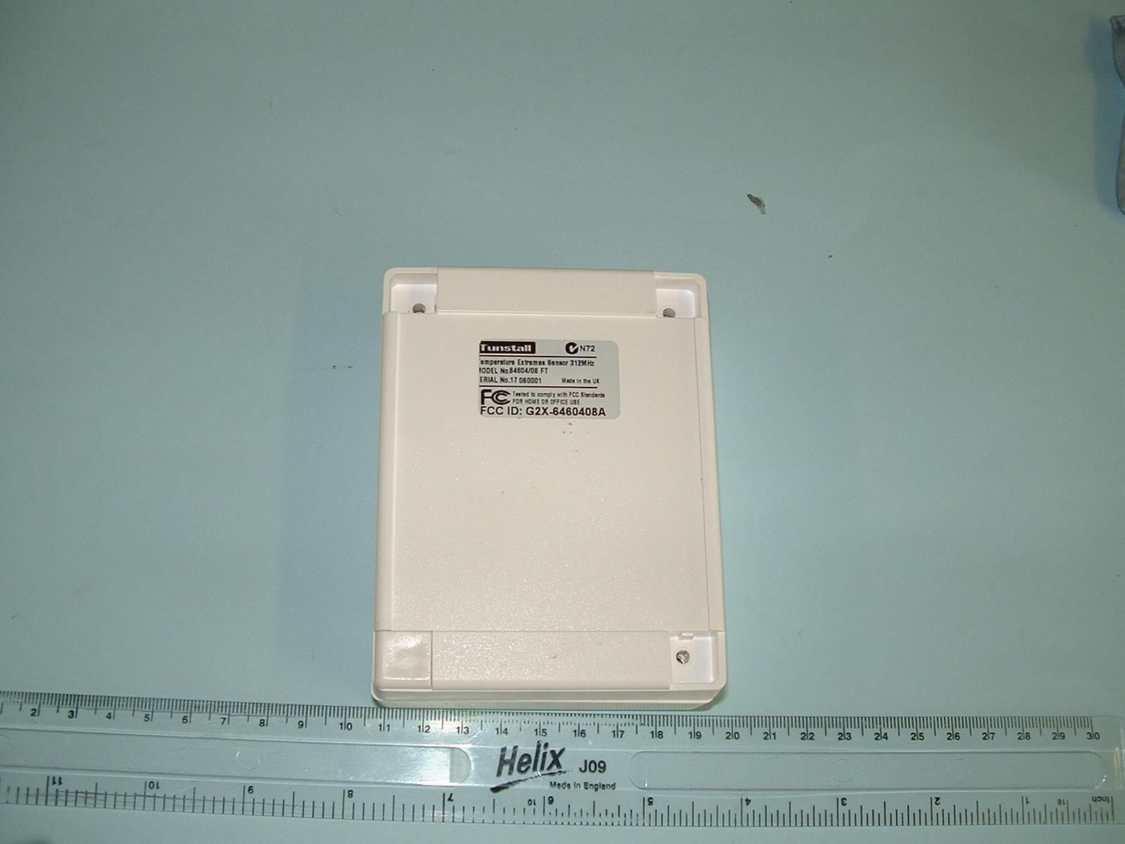
G2X-6460408ATemperature Extremes Sensor type 64604/08
Tunstall Healthcare (UK) Limited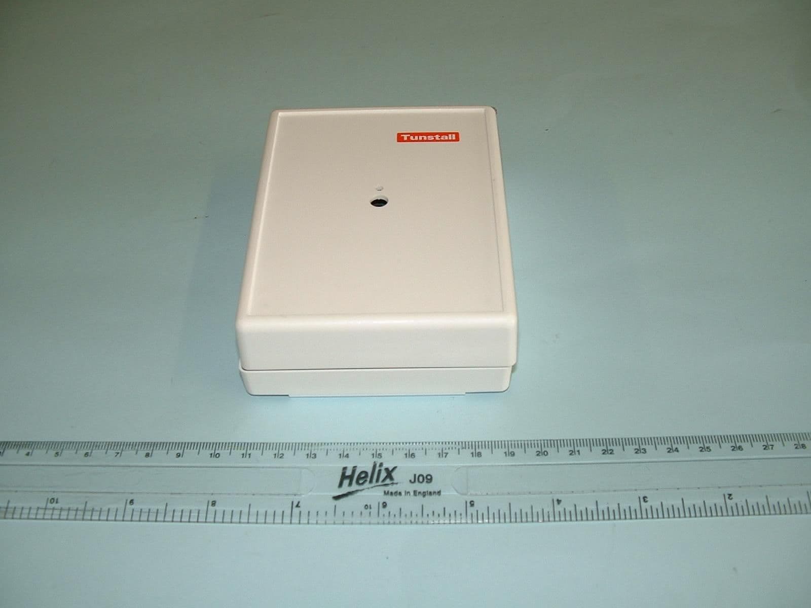
Click to zoom
Application Details
- Equipment Class
- DSC - Part 15 Security/Remote Control Transmitter
- Date of Grant
- Jun 12, 2006
- Application Purpose
- Original Equipment
- Date of Application
- Jun 12, 2006
- Equipment Note
- Temperature Extremes Sensor type 64604/08
- Frequency Range
- 311.99600000 - 312.02200000
- Country
- United Kingdom
Documents & Files
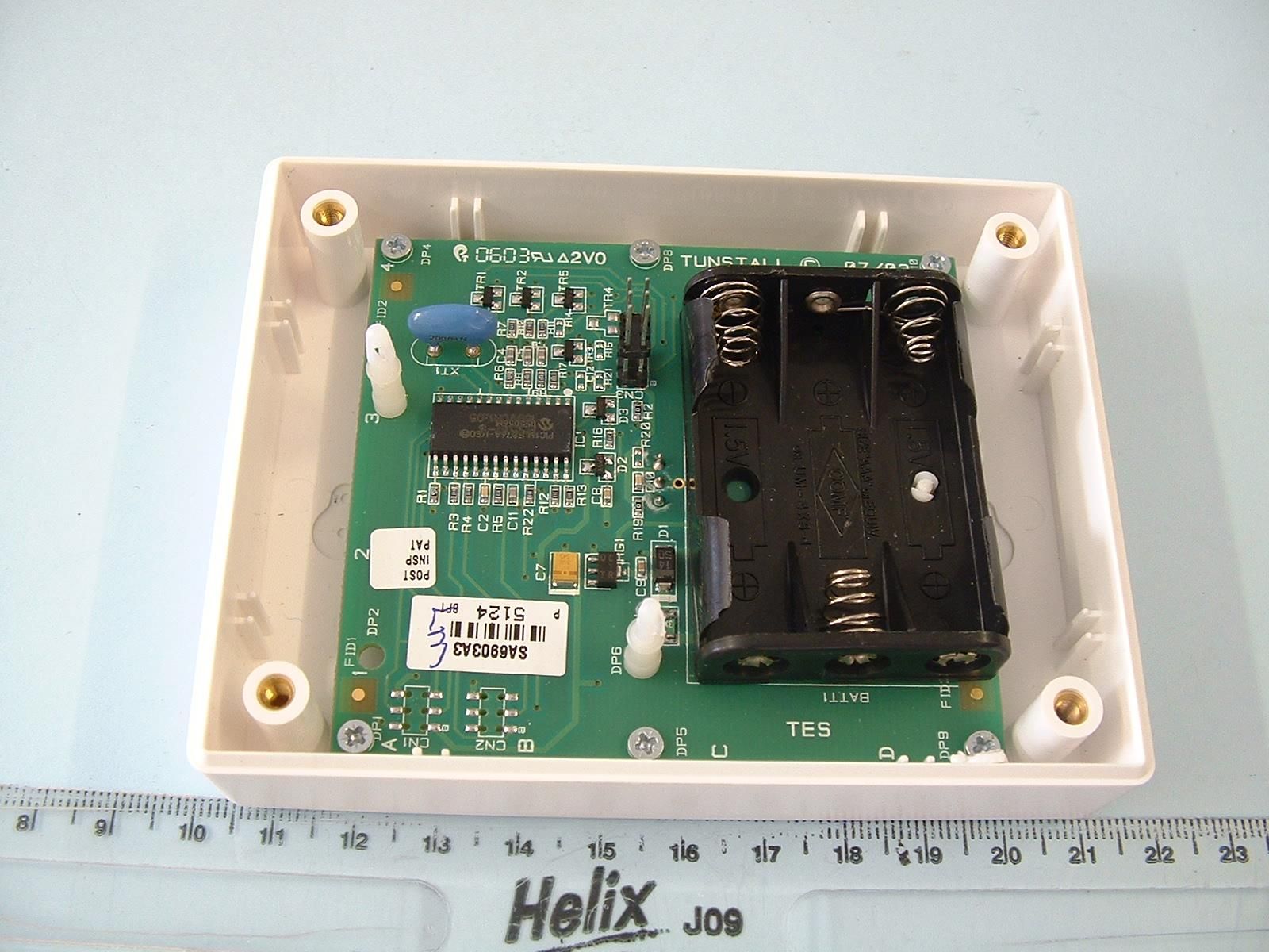
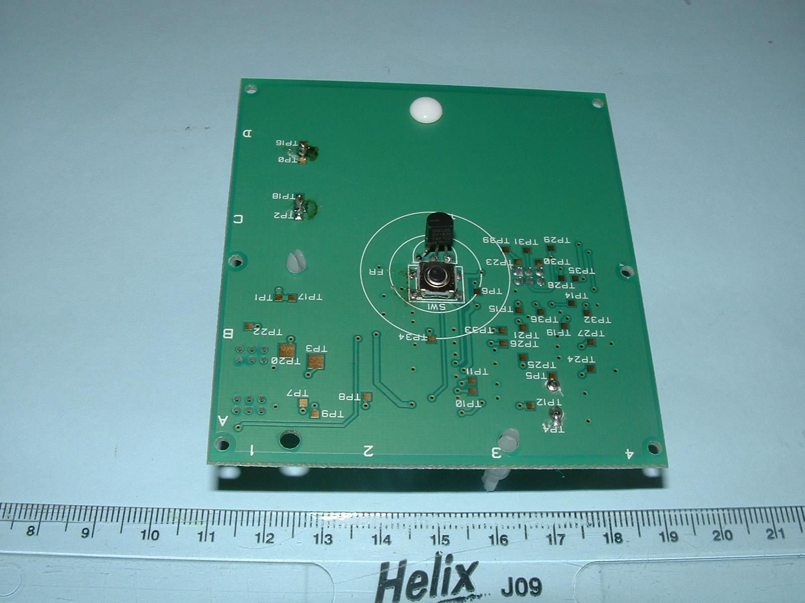
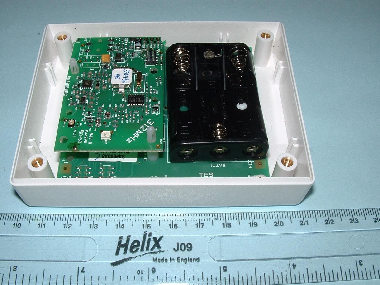
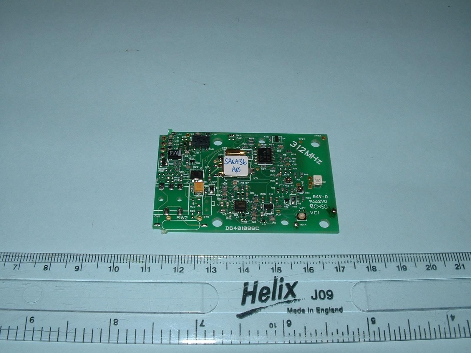
Document Text
Text extracted from the exhibit documents filed with the FCC. Open a document above to read the original.
Users Manual
D6908006A Page 1 of 4 Temperature Extremes Sensor (model 64604/08) User Guide The Temperature Extremes Sensor has been designed to detect two specific temperature thresholds, ‘high’ and ‘low’ and in addition, to monitor a rate of temperature rise (the speed at which the temperature changes). The ‘high’ temperature threshold (95 ̊F (35 ̊C)) and temperature rise detection are primarily used to indicate excessive temperatures occurring, for example, within the kitchen. The ‘low’ temperature threshold (36 ̊F (2 ̊C)) will alarm before potential freezing hazard environmental changes occur and will warn of possible water pipe bursts due to the cold temperature. The Installer will position the Temperature Extremes Sensor to protect against either high or low temperature conditions. Refer to installation section for details. If the Temperature Extremes Sensor detects a high or low temperature or a set rate of rise in temperature then an alarm call will automatically be made by the receiving equipment to a control centre. An alarm call will also be made if the Temperature Extremes Sensor detects that its battery is getting low. General Maintenance. The Temperature Extremes Sensor should be cleaned approximately every six months to ensure that the enclosure remains free of dust, cobweb and grease. The Temperature Extremes Sensor can be dusted with a dry cloth or vacuumed. A test alarm should be made following cleaning by activating the test switch. It is recommended that a test call is made at regular intervals. DO NOT USE WATER OR A DAMP CLOTH Battery Replacement None of the batteries in the unit can be replaced by the user. The product is NOT a Fire Detector. The product must not be used as a Fire Alarm The product must not be used as a Smoke Detector. The Temperature Extremes Sensor can only activate its alarm when it detects low or high temperatures. Please see the following page for these temperature settings. This alarm will not detect smoke, flame or gas. Reliance should not be placed on the Temperature Extremes Sensor product for life safety or property protection. ! ! ! ! ! D6908006A Page 2 of 4 Test Switch Installation Guide - Location of the Temperature Extremes Sensor The Temperature Extremes Sensor is intended for indoor use only. The Temperature Extremes Sensor will operate only between 14 ̊ F to 131 ̊ F (-10 ̊ C to +55 ̊ C) The Temperature Extremes Sensor can be positioned on a ceiling (maximum recommended height 8’6”/2.6m) or a wall. It is recommended that the Temperature Extremes Sensor be fitted to the ceiling when monitoring temperature rates of rise and the fixed upper temperature. The Temperature Extremes Sensor must be positioned at an approximate central point on the ceiling, away from any door or window and at least 6‘ (1.8 m) from the wall that the back of the cooker is fitted to. It should also be clear of any light fitting. The Temperature Extremes Sensor, in any event must be mounted at least 12” (30cm) away from a wall or corner. If the ceiling is not practical or, the mounting surface may become considerably warmer or cooler than the room, such as a poorly insulated ceiling, the Temperature Extremes Sensor may be mounted on the wall. It should be mounted away from a window or door and between 6” and 12” (15 and 30cm) down from the ceiling / wall intersections. It is recommended that the Temperature Extremes Sensor be fitted to the wall when monitoring cold conditions. For monitoring cold conditions the Temperature Extremes Sensor must be located in close proximity (for example within 50cms) to the area or item being protected, preferably away from any draught and avoiding locations that could expose it to accidental damage, i.e. being knocked or kicked. Ensure that the Sensor location offers a good radio transmission path to the receiving equipment. This is not normally a problem; however ensure that the Temperature Extremes Sensor is not mounted on or next to a metallic surface or structure (cabinet). The radio transmission path must be verified by holding the Sensor in the desired position and pressing the test switch, accessible through one of the Sensor’s vents. An alarm call will be sent to the receiving equipment. These calls can be cancelled at the receiving equipment. Receipt of this call will confirm adequate placement of the Temperature Extremes Sensor. Note that the Temperature Alarm Sensor must first be programmed into the receiving equipment prior to this test. Refer to the Commissioning section. If the receiving equipment is relocated within the room at any subsequent time, then the radio transmission path from the Temperature Extremes Sensor must always be verified. Installation of the Temperature Extremes Sensor Prior to installation ensure that the Temperature Extremes Sensor has been programmed to the receiving equipment. Refer to commissioning instructions. Fit the three AAA Alkaline supplied batteries to the Temperature Extremes Sensor in the correct orientation. Depiction of the correct battery orientation is moulded into the battery holder. (This must be undertaken prior to programming the receiving equipment) The Temperature Extremes Sensor is fixed to a flat surface (wall or ceiling) using the two screws provided. Two wall fixings (rawl plugs) are also provided, if required. The boxed TES contains four enclosure screws, four corner caps, four mounting feet, two rawl plugs and two wood screws. Two enclosure screws directly screw the base to the top. The other two enclosure screws fix the mounting feet to the enclosure. Two corner caps fit on the corners where there are no mounting feet. Ensure that the base is fixed securely to the mounting surface using the screws provided. Whenever the unit is opened, ensure that the rubber pad in the base locates over the batteries. D6908006A Page 3 of 4 Battery Replacement Three AAA size alkaline cells are used to supply power to the temperature sensor sub-assembly. These batteries can be replaced every 18 mo…
Text truncated - open the document above for the full version.
Test Report
TRL COMPLIANCE LTD M OSS VIEW NIPE LANE UP HOLLAND WEST LANCASHIRE WN8 9PY UNITED KINGDOM T ELEPHONE +44 (0)1695 556666 FAX +44 (0)1695 557077 E-MAIL [email protected] www.trlcompliance.com 0728 TEST REPORT NO: RU1242/6991 COPY NO: 2 ISSUE NO: 1 FCC IDS: G2X-6460408A REPORT ON THE CERTIFICATION TESTING OF A TUNSTALL TELECOM Ltd TEMPERATURE EXTREMES SENSOR WITH RESPECT TO THE FCC RULES CFR 47, PART 15.231 February 2006 INTENTIONAL RADIATOR SPECIFICATION TEST DATE: 2 nd – 8 th May 2006 TESTED BY: D WINSTANLEY APPROVED BY: P GREEN EMC PRODUCT MANAGER DATE: 12 th June 2006 Distribution: Copy Nos: 1. Tunstall Telecom Ltd 2. FCC EVALUATION LABORATORIES 3. TRL Compliance Ltd THIS DOCUMENT MAY BE REPRODUCED ONLY IN ITS ENTIRETY AND WITHOUT CHANGE TRL RF335U iss01B RU1242/6991 Page 2 of 28 CONTENTS PAGE CERTIFICATE OF CONFORMITY & COMPLIANCE 3 APPLICANT’S SUMMARY 4 EQUIPMENT TEST CONDITIONS 5 TESTS REQUIRED 5 TEST RESULTS 6-9 ANNEX PHOTOGRAPHS A PHOTOGRAPH No. 1: Test setup PHOTOGRAPH No. 2: Transmitter front view PHOTOGRAPH No. 3: Transmitter rear view PHOTOGRAPH No. 4: Control PCB track side PHOTOGRAPH No. 5: Control PCB component side PHOTOGRAPH No. 6: RF PCB track side PHOTOGRAPH No. 7: RF PCB component side APPLICANT’S SUBMISSION OF DOCUMENTATION LIST B BAND OCCUPANCY PLOT C TRANSMITTER TIMING PULSES D EQUIPMENT CALIBRATION E MEASUREMENT UNCERTAINTY F Notes: 1. Component failure during test YES NO [ ] [X] 2. If Yes, details of failure: 3. The facilities used for the testing of the product contain in this report are FCC Listed. 4. The contents of the attached applicants declarations and other supplied information are not covered by the scope of this laboratory’s UKAS or FCC accreditations’ and is provided in good faith. TRL RF335U iss01B RU1242/6991 Page 3 of 28 CERTIFICATE OF CONFORMITY & COMPLIANCE FCC IDENTITY: G2X-6460408A PURPOSE OF TEST: Certification TEST SPECIFICATION: FCC RULES CFR 47, Part 15.231 February 2006 TEST RESULT: Compliant to Specification EQUIPMENT UNDER TEST: Temperature Extremes Sensor EQUIPMENT SERIAL No: 1706001 & 1706003 ITU: EMISSION CODE: 25k9F1D EQUIPMENT TYPE: Temperature Monitoring Sensor PRODUCT USE: Personal Care Monitoring & Alarm System CARRIER EMISSION: 4415.7 μV/m @ 3m ANTENNA TYPE: Integral ALTERNATIVE ANTENNA: Not Applicable FREQUENCY OF OPERATION: 312 MHz CHANNEL SPACING: Not applicable, wideband NUMBER OF CHANNELS: 1 FREQUENCY GENERATION: SAW Resonator [ ] Crystal [X] Synthesiser [ ] MODULATION METHOD: Amplitude [ ] Digital [X] Angle [ ] POWER SOURCE(s): +4.5Vdc TEST DATE(s): 2 nd – 8 th May 2006 ORDER No(s): 57359 APPLICANT: Tunstall Telecom Ltd ADDRESS: Whitley Lodge Whitley Bridge Yorkshire DN14 0HR TESTED BY: D WINSTANLEY APPROVED BY: P GREEN EMC PRODUCT MANAGER TRL RF335U iss01B RU1242/6991 Page 4 of 28 APPLICANT’S SUMMARY EQUIPMENT UNDER TEST (EUT): Temperature Extremes Sensor EQUIPMENT TYPE: Temperature Monitoring Sensors SERIAL NUMBER OF EUT: 1706001 & 1706003 PURPOSE OF TEST: Certification TEST SPECIFICATION(s): FCC RULES CFR 47, Part 15.231 February 2006 TEST RESULT: COMPLIANT Yes No [X] [ ] APPLICANT’S CATEGORY: MANUFACTURER IMPORTER DISTRIBUTOR TEST HOUSE AGENT [X] [ ] [ ] [ ] [ ] APPLICANT’S ORDER No(s): 57359 APPLICANT’S CONTACT PERSON(s): Mr C Marcus E-mail address: [email protected] APPLICANT: Tunstall Telecom Ltd ADDRESS: Whitley Lodge Whitley Bridge Yorkshire DN14 0HR TEL: +44 (0) 1977 661234 FAX: +44(0) 1977 662452 EUT(s) COUNTRY OF ORIGIN: United Kingdom TEST LABORATORY: TRL Compliance UKAS ACCREDITATION No: 0728 TEST DATE(s): 2 nd – 8 th May 2006 TEST REPORT No: RU1242/6991 TRL RF335U iss01B RU1242/6991 Page 5 of 28 EQUIPMENT TEST / EXAMINATIONS REQUIRED 1. TEST/EXAMINATION RULE PART DETECTOR APPLICABILITY Intentional Emission Frequency: 15.231(b) Quasi Peak Yes Intentional Emission Field Strength: 15.231(b) Quasi Peak Yes Intentional Emission Band Occupancy: 15.231(c) Peak Yes Intentional Emission ERP (mW): - - No Spurious Emissions – Conducted: 15.207 - No Spurious Emissions – Radiated <1000MHz: 15.231(b) 15.209 Quasi Peak Yes Spurious Emissions – Radiated >1000MHz: 15.231(b) 15.209 Quasi Peak Average Yes Maximum Frequency of Search: 15.33 - Yes Antenna Arrangements Integral: 15.203 - Yes Antenna Arrangements External Connector: 15.204 - N/A Restricted Bands 15.205 - Yes Extrapolation Factor 15.31(f) - Yes 2. Product Use: Personal Care Monitoring & Alarm System 3. Emission Designator: 25k9F1D 4. Duty Cycle: <100% 5. Transmitter bit or pulse rate and level: 1000bps 6. Temperatures: Ambient (Tnom) 14 o C 7. Supply Voltages: Vnom +4.5Vdc Note: Vnom voltages are as stated above unless otherwise shown on the test report page Single channel [X] Two channel [ ] 8. Equipment Category: Multi-channel [ ] Narrowband [ ] Wideband [X] 9. Channel spacing: TRL RF335U iss01B RU1242/6991 Page 6 of 28 TRANSMITTER TESTS TRANSMITTER SPURIOUS EMISSIONS – RADIATED – PART 15.209 Ambient temperature = 14 o C(<1GHz) 3m measurements <1GHz [X] Relative humidity = 39% (<1GHz), 0.3m measurements >1GHz [X] Conditions = Open Area Test Site (OATS) 3m extrapolated from 0.3m [X] Supply voltage = +4.5Vdc Channel number = 1 FREQ (MHz) MEAS Rx (dBμV) CABLE LOSS (dB) ANT FACT FIELD STRENGTH (dBμV/m) EXTRAP FACTOR (dB) FIELD STRENGTH (μV/m) Limit (μV/m) 30MHz - 88MHz 88MHz - 216MHz 216MHz - 960MHz 624.00 936.00 29.35 29.20 3.1 3.9 18.75 21.20 51.2 54.3 - - 363.1 518.8 592 592 960MHz - 1GHz 1GHz - 5GHz 1248.006 1560.080 1872.010 2184.016 2496.010(r) 2808.130(r) 38.08 36.45 40.38 36.10 36.31 30.62 0.30 0.30 0.31 0.39 0.53 0.50 24.3 25.5 26.0 27.8 28.0 29.0 62.68 62.25 66.69 64.29 64.84 60.12 20 20 20 20 20 20 136.1 129.6 216.0 163.9 174.6 101.4 592 592 592 592 500 500 1.705MHz to 30MHz 30μV/m @ 30m 30MHz to 88MHz 100μV/m @ 3m 88MHz to 216MHz 150μV/m @ 3m 216MHz to 960MHz 200μV/m @ 3m 960MHz to 1GHz 500μV/m @ 3m Limits 1GHz to 5GHz 500μV/m @ 3m Notes: 1 Results quoted are extrapolated as indicated. 2 Emissions were searched to: (x) 1000MHz inclusive, as per Pa…
Text truncated - open the document above for the full version.
Test Setup Photos
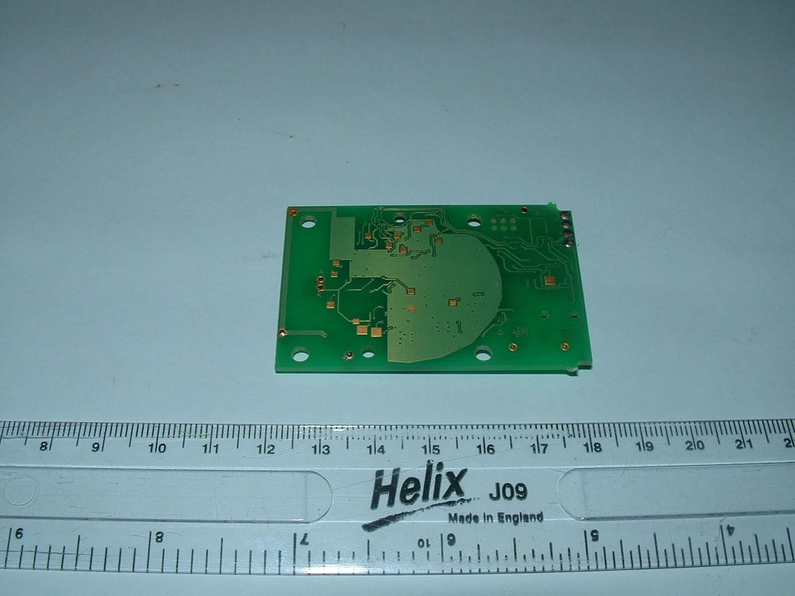
TRL RF335U iss01B RU1242/6991 Page 11 of 28 PHOTOGRAPH No. 1 TEST SETUP
Contact Information
Applicant
Mark Jennings(Chief Engineer)
Technical Contact
Tunstall Group LtdChris Marcus
[email protected]+44 1977 661234
Whitley Lodge · Doncaster · United Kingdom
Test Firm
TRL Compliance LtdJohn Charters
Technical Specifications
| # | Rule Parts | Frequency Range | Power Output |
|---|---|---|---|
| 1 | 15.231 | 311.996 MHz - 312.022 MHz | - |
Other Applications from Tunstall Healthcare (UK) Limited
G2X-646041E
May 14, 2013312 Ei Smoke Alarm Model 64604/14
Equipment Class
DSC - Part 15 Security/Remote Control Transmitter
G2X-66004V
Dec 17, 201266004/09 iVi Personal Fall Detector.
Equipment Class
DXX - Part 15 Low Power Communication Device Transmitter
G2X-6360412
Dec 06, 201263604/12 Amie Personal Fall Alarm
Equipment Class
DXX - Part 15 Low Power Communication Device Transmitter
G2X66004
Jan 29, 2008312 Fall Detector
Equipment Class
DSC - Part 15 Security/Remote Control Transmitter
G2X-6460474A
Dec 15, 2006Radio Smoke Detector model 64604/74
Equipment Class
DSC - Part 15 Security/Remote Control Transmitter