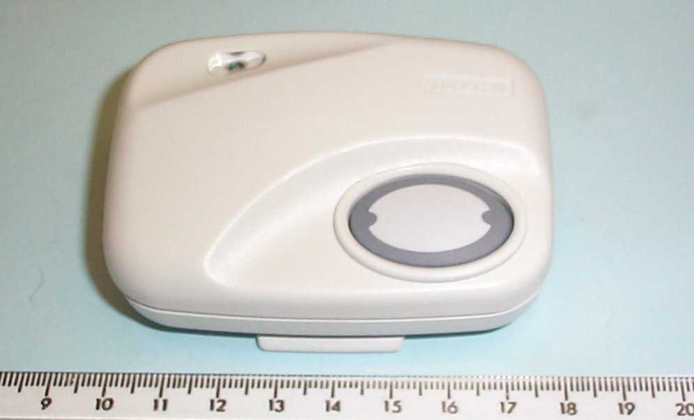
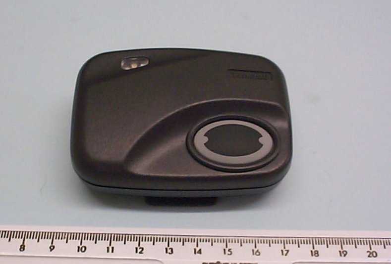
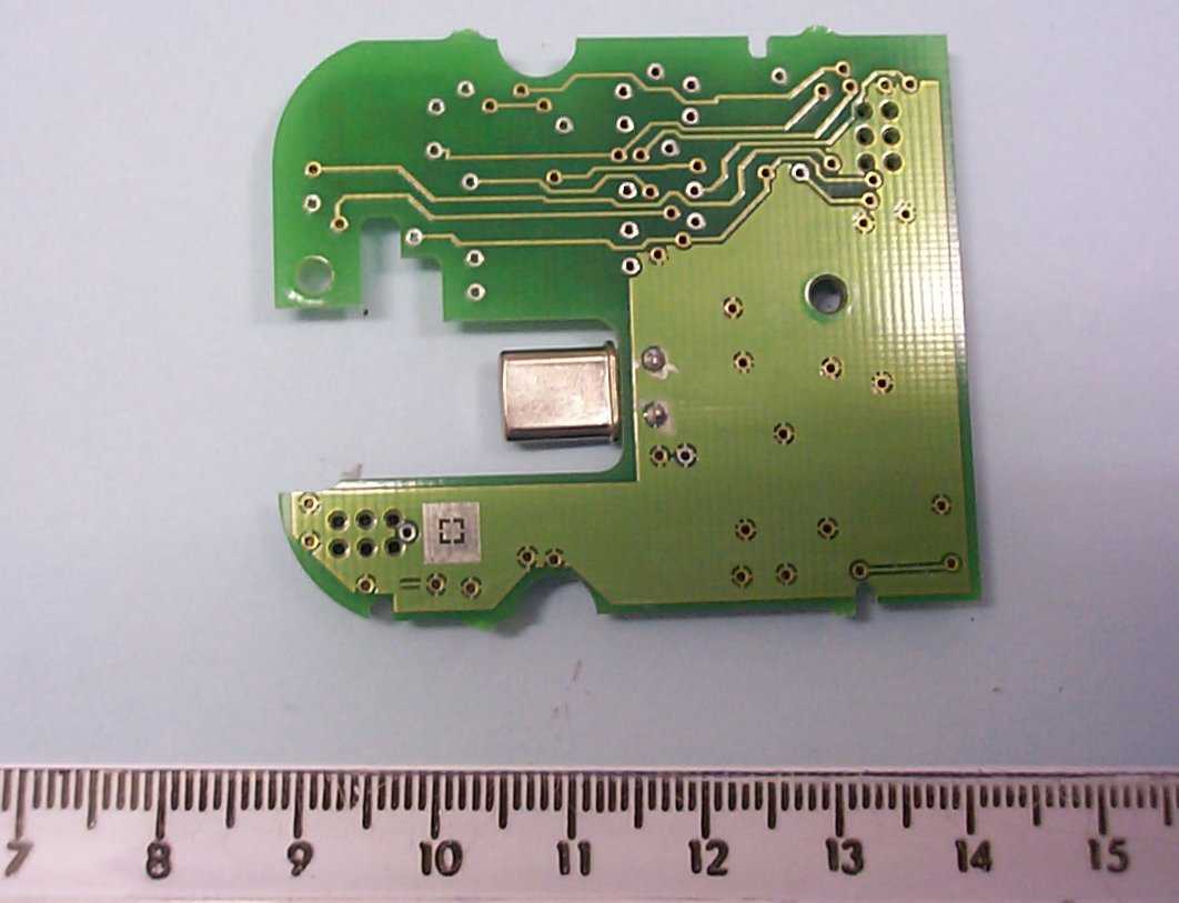
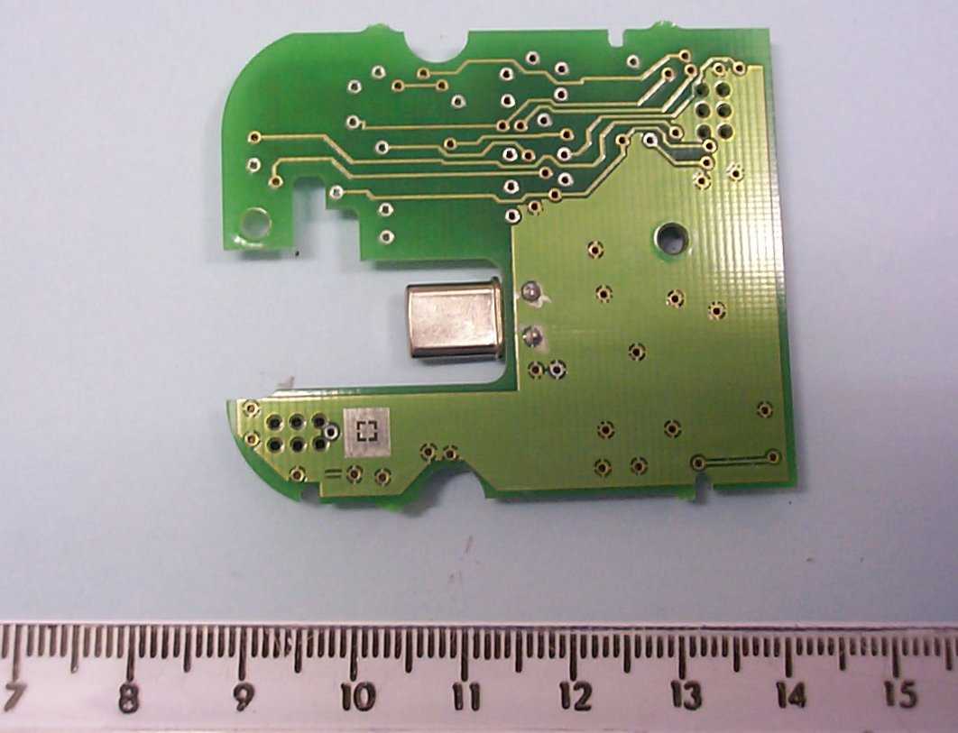
G2X-66004AFall Detector
Tunstall Healthcare (UK) Limited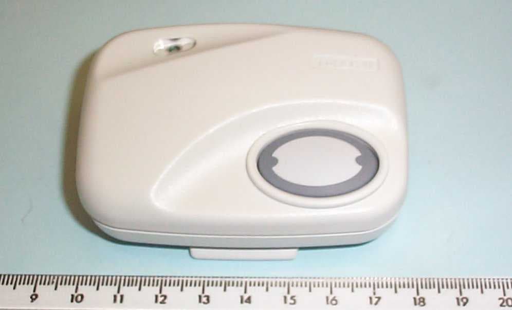
Click to zoom
Application Details
- Equipment Class
- DSC - Part 15 Security/Remote Control Transmitter
- Date of Grant
- Feb 01, 2004
- Application Purpose
- Original Equipment
- Date of Application
- Jan 28, 2004
- Equipment Note
- Fall Detector
- Frequency Range
- 312.00000000 - 312.00000000
- Country
- United Kingdom
Documents & Files
Document Text
Text extracted from the exhibit documents filed with the FCC. Open a document above to read the original.
Users Manual
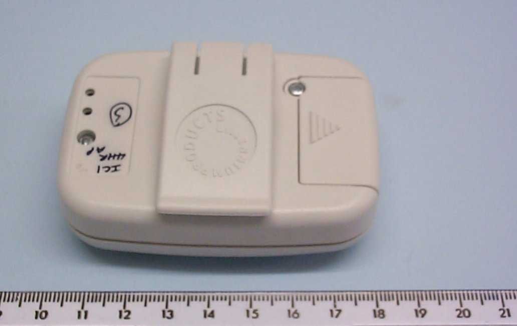
All the reassurance you need D66070xx Issue APage 1 of 10 Fall Detector™ User Instructions Manual trigger button Activity indicator Battery Cover Belt / clothing clip All the reassurance you need D66070xx Issue APage 2 of 10 Your fall detector™ is a battery operated device containing a microprocessor, detector and a radio transmitter. It will automatically trigger an alarm call on your community alarm system if it detects that you have fallen. You can also use it to manually raise an alarm call. Wearing the fall detector • Clip the fall detector to your belt or clothing in the upright position shown in the drawing. It needs to be in the upright position to reduce the possibility of false activation. 9 8 Upright position Incorrect position All the reassurance you need D66070xx Issue APage 3 of 10 Automatic fall detection • Green light and two "beeps" indicates that the fall detector has been activated. • The fall detector will then monitor for between 6 and 15 seconds to verify if there could have been a fall. The green light will flash while it does this. • If the detector has decided that there is a fall, then a red light and four "beeps" indicates that the fall detector is about to trigger an alarm call (because it has detected an impact and has not been upright for between 6 and 15 seconds). • If the detector has decided that it was activated by error then the green flashing light will stop after between 6 to 15 Seconds and the unit will revert to normal again. • Due to the complex dynamics of falling, all falls may not be detected. In this unlikely event the manual button can still be used to call for help. All the reassurance you need D66070xx Issue APage 4 of 10 Manual operation • Press the button on the fall detector to raise a manual alarm call. • The fall detector will "beep" and a red light indicates the fall detector is triggering an alarm call. • If the red light flashes on and off, the fall detector is still triggering an alarm call, but is also indicating to you that the battery needs to be replaced. All the reassurance you need D66070xx Issue APage 5 of 10 • Remember, the fall detector will only detect you falling if you are wearing it. • The fall detector must be worn at or above the waist, where it will detect the maximum number of falls. • When removing the fall detector, handle carefully to avoid false calls, place it on an even surface in the upright position and preferably in the stand provided. • If the fall detector does wake up and beep when you know you have not fallen, you can prevent it raising an alarm by ensuring that it is returned to an upright position. • It is not recommended that you wear the fall detector whilst in bed, as normal movement in bed will cause the fall detector to trigger. All the reassurance you need D66070xx Issue APage 6 of 10 Battery Replacement From time to time the battery will need replacing, you will know this because somebody from your monitoring service (if you have one) may inform you, or you may see the red light flashing rather than staying on continuously when a manual alarm call is made. • The unit automatically tests the battery several times within each 24 hour period. It is able to automatically generate an alarm call when low battery is detected. • If it is necessary for you to change the battery, the fall detector uses a 6 volt Duracell PX28L battery. • To access the battery, remove the battery cover screw and then the battery cover by sliding it in the direction of the arrow. • After a year the battery should be replaced. Contact your provider for a replacement. In many cases your provider will change the battery for you. On the back of this user guide is a handy table to All the reassurance you need D66070xx Issue APage 7 of 10 help you remember when the battery should be changed. • Remove battery and replace it with the new battery, remember to observe the correct orientation. When the battery is first placed in the unit an automatic test call will be generated (no lights will show and no buzzer will sound). • Replace the sliding cover and the screw. Test the fall detector by making a manual call. Inform the operator that you are making a battery test call. • If the device fails to make a test call then check the orientation of the battery. If this is correct then contact your supplier. Do not dispose of the old battery in the bin, please return it to Tunstall (c/o Service Centre) at the address shown overleaf. Li 1. First remove the screw. 2. Then slide the cover off in the direction of the arrow. + 3. Orientation (copper end). All the reassurance you need D66070xx Issue APage 8 of 10 Care of the fall detector • Avoid getting the fall detector wet (if it does then dry it quickly and make a manual test call to confirm it is working correctly). • If required, the fall detector may be cleaned periodically with a damp cloth and mild detergent. • It is recommended that you test the fall detector once a month: • Make a manual test call. • Tap the fall detector when it is lying down. After 5 Seconds the fall detector should beep and the green light start to flash. If you put the unit quickly back upright (in its stand, for instance), the alarm call will not be raised. Manufactured By Tunstall Telecom Ltd. Whitley Lodge Whitley Bridge Yorkshire DN14 OHR Tel : 01977 661234 Fax: 01977 662963 www.tunstallgroup.com Supplied By All the reassurance you need D66070xx Issue APage 9 of 10 Radio Approval Notices Australia The Fall Detector operates on a frequency of 312MHz and is certified approved by TRL Compliance to AS/NZS 4268:2003 Canada Canadian Certification Approvals Number IC: 1231A-66004A USA Federal Communications Commission (FCC) notices This equipment has been tested and found to comply with the limits for a Class B digital device, pursuant to part 15 of the FCC Rules. These limits are designed to provide reasonable protection against harmful interference in a residential installation. This equipment generates, uses and c…
Text truncated - open the document above for the full version.
Users Manual
All the reassurance you need D66070xx Issue APage 1 of 10 Fall Detector™ User Instructions Manual trigger button Activity indicator Battery Cover Belt / clothing clip All the reassurance you need D66070xx Issue APage 2 of 10 Your fall detector™ is a battery operated device containing a microprocessor, detector and a radio transmitter. It will automatically trigger an alarm call on your community alarm system if it detects that you have fallen. You can also use it to manually raise an alarm call. Wearing the fall detector • Clip the fall detector to your belt or clothing in the upright position shown in the drawing. It needs to be in the upright position to reduce the possibility of false activation. 9 8 Upright position Incorrect position All the reassurance you need D66070xx Issue APage 3 of 10 Automatic fall detection • Green light and two "beeps" indicates that the fall detector has been activated. • The fall detector will then monitor for between 6 and 15 seconds to verify if there could have been a fall. The green light will flash while it does this. • If the detector has decided that there is a fall, then a red light and four "beeps" indicates that the fall detector is about to trigger an alarm call (because it has detected an impact and has not been upright for between 6 and 15 seconds). • If the detector has decided that it was activated by error then the green flashing light will stop after between 6 to 15 Seconds and the unit will revert to normal again. • Due to the complex dynamics of falling, all falls may not be detected. In this unlikely event the manual button can still be used to call for help. All the reassurance you need D66070xx Issue APage 4 of 10 Manual operation • Press the button on the fall detector to raise a manual alarm call. • The fall detector will "beep" and a red light indicates the fall detector is triggering an alarm call. • If the red light flashes on and off, the fall detector is still triggering an alarm call, but is also indicating to you that the battery needs to be replaced. All the reassurance you need D66070xx Issue APage 5 of 10 • Remember, the fall detector will only detect you falling if you are wearing it. • The fall detector must be worn at or above the waist, where it will detect the maximum number of falls. • When removing the fall detector, handle carefully to avoid false calls, place it on an even surface in the upright position and preferably in the stand provided. • If the fall detector does wake up and beep when you know you have not fallen, you can prevent it raising an alarm by ensuring that it is returned to an upright position. • It is not recommended that you wear the fall detector whilst in bed, as normal movement in bed will cause the fall detector to trigger. All the reassurance you need D66070xx Issue APage 6 of 10 Battery Replacement From time to time the battery will need replacing, you will know this because somebody from your monitoring service (if you have one) may inform you, or you may see the red light flashing rather than staying on continuously when a manual alarm call is made. • The unit automatically tests the battery several times within each 24 hour period. It is able to automatically generate an alarm call when low battery is detected. • If it is necessary for you to change the battery, the fall detector uses a 6 volt Duracell PX28L battery. • To access the battery, remove the battery cover screw and then the battery cover by sliding it in the direction of the arrow. • After a year the battery should be replaced. Contact your provider for a replacement. In many cases your provider will change the battery for you. On the back of this user guide is a handy table to All the reassurance you need D66070xx Issue APage 7 of 10 help you remember when the battery should be changed. • Remove battery and replace it with the new battery, remember to observe the correct orientation. When the battery is first placed in the unit an automatic test call will be generated (no lights will show and no buzzer will sound). • Replace the sliding cover and the screw. Test the fall detector by making a manual call. Inform the operator that you are making a battery test call. • If the device fails to make a test call then check the orientation of the battery. If this is correct then contact your supplier. Do not dispose of the old battery in the bin, please return it to Tunstall (c/o Service Centre) at the address shown overleaf. Li 1. First remove the screw. 2. Then slide the cover off in the direction of the arrow. + 3. Orientation (copper end). All the reassurance you need D66070xx Issue APage 8 of 10 Care of the fall detector • Avoid getting the fall detector wet (if it does then dry it quickly and make a manual test call to confirm it is working correctly). • If required, the fall detector may be cleaned periodically with a damp cloth and mild detergent. • It is recommended that you test the fall detector once a month: • Make a manual test call. • Tap the fall detector when it is lying down. After 5 Seconds the fall detector should beep and the green light start to flash. If you put the unit quickly back upright (in its stand, for instance), the alarm call will not be raised. Manufactured By Tunstall Telecom Ltd. Whitley Lodge Whitley Bridge Yorkshire DN14 OHR Tel : 01977 661234 Fax: 01977 662963 www.tunstallgroup.com Supplied By All the reassurance you need D66070xx Issue APage 9 of 10 Radio Approval Notices Australia The Fall Detector operates on a frequency of 312MHz and is certified approved by TRL Compliance to AS/NZS 4268:2003 Canada Canadian Certification Approvals Number IC: 1231A-66004A USA Federal Communications Commission (FCC) notices This equipment has been tested and found to comply with the limits for a Class B digital device, pursuant to part 15 of the FCC Rules. These limits are designed to provide reasonable protection against harmful interference in a residential installation. This equipment generates, uses and c…
Text truncated - open the document above for the full version.
ID Label/Location Info
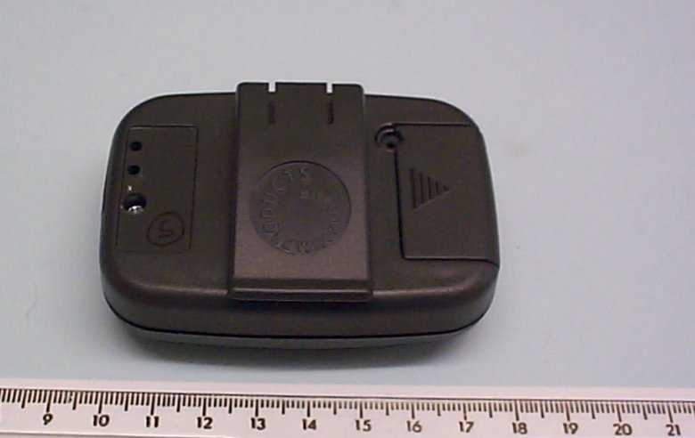
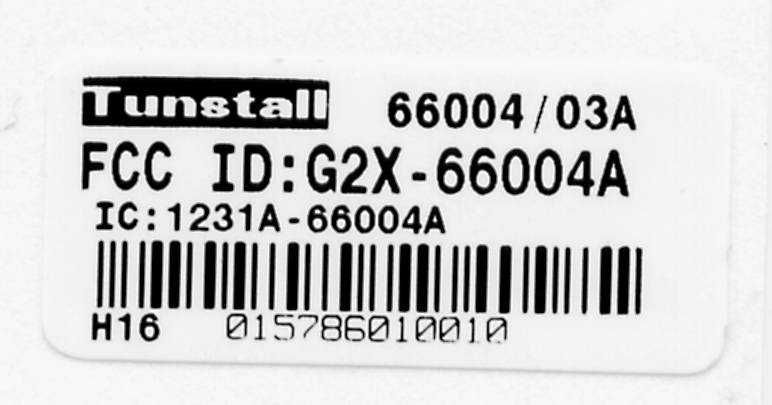
Battery Cover Belt / clothing clip FCC ID Label
ID Label/Location Info
Battery Cover Belt / clothing clip FCC ID Label
Test Report
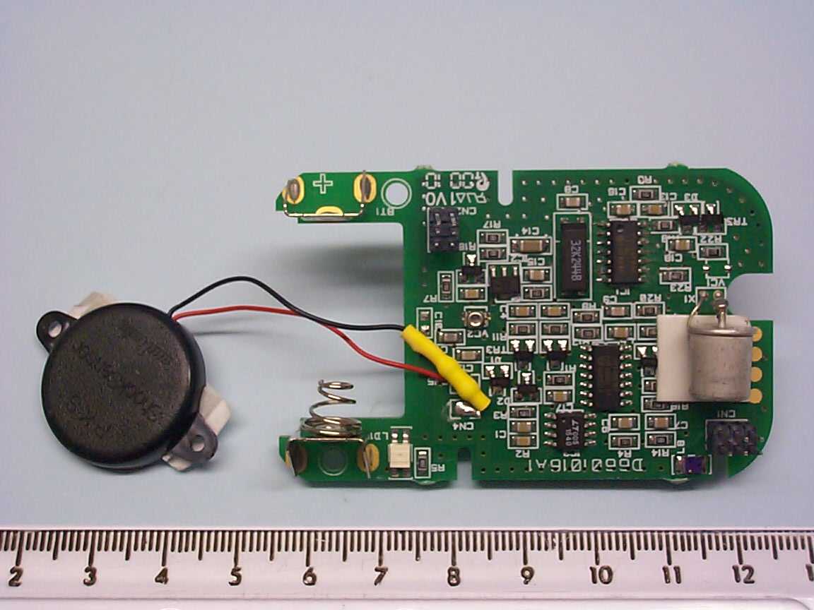
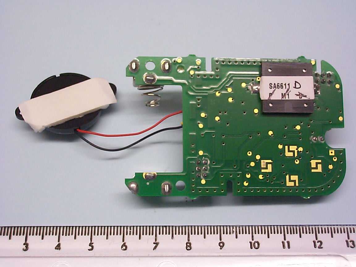
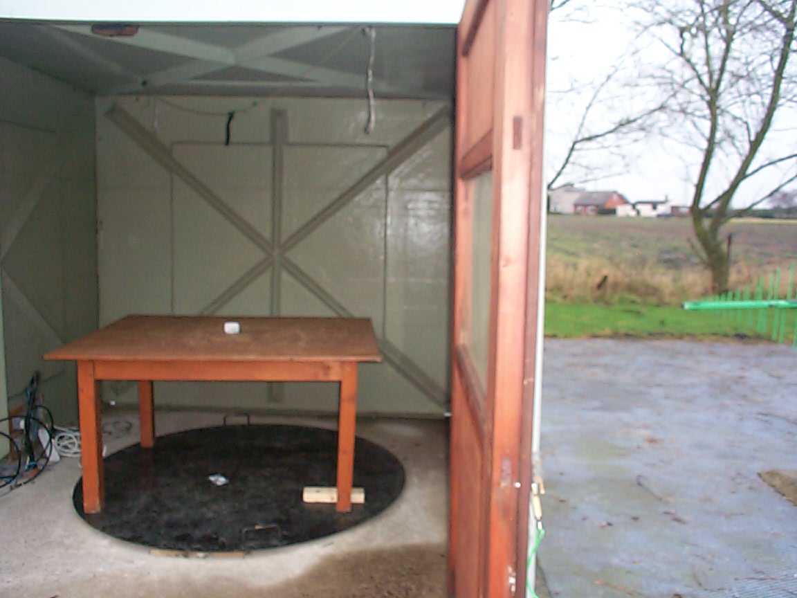
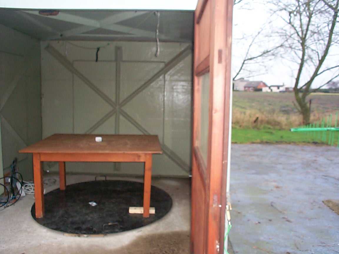
TRL C OMPLIANCE S ERVICES L TD EMC DIVISION MOSS VIEW NIPE LANE UP HOLLAND WEST LANCASHIRE WN8 9PY UNITED KINGDOM TELEPHONE +44 (0)1695 556666 FAX +44 (0)1695 557077 E- MAIL [email protected] www.trlcompliance.com FS 21805 TEST REPORT NO:RU1097/5206 COPY NO:3 ISSUE NO:1 FCC ID:G2X-66004A REPORT ON THE CERTIFICATION TESTING OF A Tunstall Telecom Limited 312MHz Fall Detector Transmitter WITH RESPECT TO THE FCC RULES CFR 47, PART 15.231 INTENTIONAL RADIATOR SPECIFICATION TEST DATE: 12 th – 16 th January 2004 TESTED BY:J Charters APPROVED BY:P Green Product Manager DATE:27 th January 2004 Distribution: Copy Nos:1.Tunstall Telecom Limited 2.FCC EVALUATION LABORATORIES 3.TRL EMC THIS DOCUMENT MAY BE REPRODUCED ONLY IN ITS ENTIRETY AND WITHOUT CHANGE RF335U iss03RU1097/5206Page 2 of 27 CONTENTS PAGE CERTIFICATE OF CONFORMITY & COMPLIANCE3 APPLICANT’S SUMMARY4 EQUIPMENT TEST CONDITIONS4 TESTS REQUIRED5 TEST RESULTS6-9 ANNEX PHOTOGRAPHSA PHOTOGRAPH No. 1: Test setup PHOTOGRAPH No. 2: Transmitter front view PHOTOGRAPH No. 3: Transmitter rear view PHOTOGRAPH No. 4: Transmitter PCB track side PHOTOGRAPH No. 5: Transmitter PCB component side PHOTOGRAPH No. 6: PCB 2 component side PHOTOGRAPH No. 7: PCB 2 Track side APPLICANT’S SUBMISSION OF DOCUMENTATION LISTB BAND OCCUPANCY PLOTC TRANSMITTER ON TIMED Notes: 1.Component failure during testYES NO [ ] [X] 2.If Yes, details of failure: 3.The facilities used for the testing of the product contain in this report are FCC Listed. 4.The contents of the attached applicants declarations and other supplied information are not covered by the scope of this laboratory’s UKAS or FCC accreditations’ and is provided in good faith. RF335U iss03RU1097/5206Page 3 of 27 CERTIFICATE OF CONFORMITY & COMPLIANCE FCC IDENTITY:G2X-66004A PURPOSE OF TEST:Certification TEST SPECIFICATION:FCC RULES CFR 47, Part 15.231 TEST RESULT:Compliant to Specification EQUIPMENT UNDER TEST:312MHz Fall Detector Transmitter EQUIPMENT SERIAL No:Engineering sample ITU: EMISSION CODE:3K00F1DAN EQUIPMENT TYPE:66004A PRODUCT USE:Nurse/help call CARRIER EMISSION: 2660.7μV/m ANTENNA TYPE:PCB integral ALTERNATIVE ANTENNA:N/A BAND OF OPERATION:260MHz – 470MHz CHANNEL SPACING:N/A Wideband NUMBER OF CHANNELS:1 FREQUENCY GENERATION:SAW Resonator[ ]Crystal[X]Synthesiser [ ] MODULATION METHOD:Amplitude[ ]Digital[ ]Angle [ ] POWER SOURCE(s):6Vdc battery TEST DATE(s):12 th - 16 th January 2004 ORDER No(s):256284 APPLICANT:Tunstall Telecom Limited ADDRESS:Whitley Lodge Whitley Bridge Yorkshire DN14 0HR TESTED BY:J Charters APPROVED BY:P Green Product Manager RF335U iss03RU1097/5206Page 4 of 27 APPLICANT’S SUMMARY EQUIPMENT UNDER TEST (EUT):312MHz Fall Detector Transmitter EQUIPMENT TYPE:66004A SERIAL NUMBER OF EUT:Engineering sample PURPOSE OF TEST:Certification TEST SPECIFICATION(s):FCC RULES CFR 47, Part 15.231 TEST RESULT:COMPLIANTYes No [X] [ ] APPLICANT’S CATEGORY:MANUFACTURER IMPORTER DISTRIBUTOR TEST HOUSE AGENT [X] [ ] [ ] [ ] [ ] APPLICANT’S ORDER No(s):256284 APPLICANT’S CONTACT PERSON(s):Mr R Nadin E-mail address:[email protected] APPLICANT:Tunstall Telecom Limited ADDRESS:Whitley Lodge Whitley Bridge Yorkshire DN14 0HR TEL:+44 1977 660398 FAX:+44 1977 660550 MANUFACTURER:Tunstall Telecom Limited EUT(s) COUNTRY OF ORIGIN:United Kingdom TEST LABORATORY:TRL EMC UKAS ACCREDITATION No:0728 TEST DATE(s)12 th – 16 th January 2004 TEST REPORT No:RU1097/5206 RF335U iss03RU1097/5206Page 5 of 27 EQUIPMENT TEST / EXAMINATIONS REQUIRED 1. TEST/EXAMINATIONRULE PARTDETECTORAPPLICABILITY Intentional Emission Frequency:15.231(b)Quasi PeakYes Intentional Emission Field Strength:15.231(b)Quasi PeakYes Intentional Emission Band Occupancy:15.231(c)PeakYes Intentional Emission ERP (mW):--No Spurious Emissions – Conducted:15.207-No Spurious Emissions – Radiated <1000MHz: 15.231(b) 15.209 Quasi Peak Average Yes Spurious Emissions – Radiated >1000MHz: 15.231 15.209(b) Quasi Peak Average Yes Maximum Frequency of Search:15.33-Yes Antenna Arrangements Integral:15.203-Yes Antenna Arrangements External Connector:15.204-Yes Restricted Bands15.205-Yes Extrapolation Factor15.31(f)-Yes 2.Product Use:Nurse/help call 3.Emission Designator:3K00F1DAN 4.Duty Cycle:<1% 5.Transmitter bit or pulse rate and level:20BPS 6.Temperatures:Ambient (Tnom)9 o C 7.Supply Voltages:Vnom6Vdc Note: Vnom voltages are as stated above unless otherwise shown on the test report page Single channel[X] Two channel[ ] 8.Equipment Category: Multi-channel[ ] Narrowband[ ] Wideband[X] 9.Channel spacing: RF335U iss03RU1097/5206Page 6 of 27 TRANSMITTER TESTS TRANSMITTER SPURIOUS EMISSIONS – RADIATED – PART 15.209 Ambient temperature=9 o C(<1GHz)3m measurements <1GHz[X] Relative humidity=73% (<1GHz),0.3m measurements >1GHz[X] Conditions=Open Area Test Site (OATS)0.3m extrapolated to 1m[X] Supply voltage=6Vdc Channel number=1 FREQ. (MHz) MEAS Rx. (dBμV) CABLE LOSS (dB) ANT FACT. FIELD STRENGTH (dBμV/m) EXTRAP. FACTOR (dB) FIELD STRENGTH (μV/m) LIMIT (μV/m) 30MHz- 88MHz 88MHz-216MHz 216MHz-960MHz624.027.32.918.849.0-281.83588 960MHz-1GHz 1GHz-5GHz 1247.9 1559.9(R) 1871.9 2183.97 2495.9(R) 2807.9(R) 33.14 39.59 40.47 24.14 24.4 25.44 0.6 0.65 0.67 0.81 0.72 0.72 24.95 25.7 26.7 28.0 28.9 29.75 58.69 65.94 67.84 52.95 54.02 55.91 20 20 20 20 20 20 86.0 198.2 246.6 44.4 50.2 62.4 588 500 588 588 500 500 1.705MHz to 30MHz 30μV/m@ 30m 30MHz to 88MHz100μV/m@ 3m 88MHz to 216MHz150μV/m@ 3m 216MHz to 960MHz200μV/m@ 3m 960MHz to 1GHz500μV/m@ 3m Limits 1GHz to 5GHz500μV/m@ 3m Notes: 1Results quoted are extrapolated as indicated 2 Emissions were searched to: (x) 1000MHz inclusive, as per Part 15.33a 3Extrapolation factor 20dB from 0.m to 3m, as per Part 15.31f 4Measurements >1GHz @ 1m as per Part 15.31f(1) 5Receiver detector >1GHz = CISPR, Quasi-Peak, 120kHz bandwidth 6Receiver detector >1GHz = Peak Hold, 1MHz resolution bandwidth 7New batteries used for battery powered products. 8(R) indicated frequency within restricted band from 15.205 9Due to the transmitted signal lasting …
Text truncated - open the document above for the full version.
Test Report
TRL C OMPLIANCE S ERVICES L TD EMC DIVISION MOSS VIEW NIPE LANE UP HOLLAND WEST LANCASHIRE WN8 9PY UNITED KINGDOM TELEPHONE +44 (0)1695 556666 FAX +44 (0)1695 557077 E- MAIL [email protected] www.trlcompliance.com FS 21805 TEST REPORT NO:RU1097/5206 COPY NO:3 ISSUE NO:1 FCC ID:G2X-66004A REPORT ON THE CERTIFICATION TESTING OF A Tunstall Telecom Limited 312MHz Fall Detector Transmitter WITH RESPECT TO THE FCC RULES CFR 47, PART 15.231 INTENTIONAL RADIATOR SPECIFICATION TEST DATE: 12 th – 16 th January 2004 TESTED BY:J Charters APPROVED BY:P Green Product Manager DATE:27 th January 2004 Distribution: Copy Nos:1.Tunstall Telecom Limited 2.FCC EVALUATION LABORATORIES 3.TRL EMC THIS DOCUMENT MAY BE REPRODUCED ONLY IN ITS ENTIRETY AND WITHOUT CHANGE RF335U iss03RU1097/5206Page 2 of 27 CONTENTS PAGE CERTIFICATE OF CONFORMITY & COMPLIANCE3 APPLICANT’S SUMMARY4 EQUIPMENT TEST CONDITIONS4 TESTS REQUIRED5 TEST RESULTS6-9 ANNEX PHOTOGRAPHSA PHOTOGRAPH No. 1: Test setup PHOTOGRAPH No. 2: Transmitter front view PHOTOGRAPH No. 3: Transmitter rear view PHOTOGRAPH No. 4: Transmitter PCB track side PHOTOGRAPH No. 5: Transmitter PCB component side PHOTOGRAPH No. 6: PCB 2 component side PHOTOGRAPH No. 7: PCB 2 Track side APPLICANT’S SUBMISSION OF DOCUMENTATION LISTB BAND OCCUPANCY PLOTC TRANSMITTER ON TIMED Notes: 1.Component failure during testYES NO [ ] [X] 2.If Yes, details of failure: 3.The facilities used for the testing of the product contain in this report are FCC Listed. 4.The contents of the attached applicants declarations and other supplied information are not covered by the scope of this laboratory’s UKAS or FCC accreditations’ and is provided in good faith. RF335U iss03RU1097/5206Page 3 of 27 CERTIFICATE OF CONFORMITY & COMPLIANCE FCC IDENTITY:G2X-66004A PURPOSE OF TEST:Certification TEST SPECIFICATION:FCC RULES CFR 47, Part 15.231 TEST RESULT:Compliant to Specification EQUIPMENT UNDER TEST:312MHz Fall Detector Transmitter EQUIPMENT SERIAL No:Engineering sample ITU: EMISSION CODE:3K00F1DAN EQUIPMENT TYPE:66004A PRODUCT USE:Nurse/help call CARRIER EMISSION: 2660.7μV/m ANTENNA TYPE:PCB integral ALTERNATIVE ANTENNA:N/A BAND OF OPERATION:260MHz – 470MHz CHANNEL SPACING:N/A Wideband NUMBER OF CHANNELS:1 FREQUENCY GENERATION:SAW Resonator[ ]Crystal[X]Synthesiser [ ] MODULATION METHOD:Amplitude[ ]Digital[ ]Angle [ ] POWER SOURCE(s):6Vdc battery TEST DATE(s):12 th - 16 th January 2004 ORDER No(s):256284 APPLICANT:Tunstall Telecom Limited ADDRESS:Whitley Lodge Whitley Bridge Yorkshire DN14 0HR TESTED BY:J Charters APPROVED BY:P Green Product Manager RF335U iss03RU1097/5206Page 4 of 27 APPLICANT’S SUMMARY EQUIPMENT UNDER TEST (EUT):312MHz Fall Detector Transmitter EQUIPMENT TYPE:66004A SERIAL NUMBER OF EUT:Engineering sample PURPOSE OF TEST:Certification TEST SPECIFICATION(s):FCC RULES CFR 47, Part 15.231 TEST RESULT:COMPLIANTYes No [X] [ ] APPLICANT’S CATEGORY:MANUFACTURER IMPORTER DISTRIBUTOR TEST HOUSE AGENT [X] [ ] [ ] [ ] [ ] APPLICANT’S ORDER No(s):256284 APPLICANT’S CONTACT PERSON(s):Mr R Nadin E-mail address:[email protected] APPLICANT:Tunstall Telecom Limited ADDRESS:Whitley Lodge Whitley Bridge Yorkshire DN14 0HR TEL:+44 1977 660398 FAX:+44 1977 660550 MANUFACTURER:Tunstall Telecom Limited EUT(s) COUNTRY OF ORIGIN:United Kingdom TEST LABORATORY:TRL EMC UKAS ACCREDITATION No:0728 TEST DATE(s)12 th – 16 th January 2004 TEST REPORT No:RU1097/5206 RF335U iss03RU1097/5206Page 5 of 27 EQUIPMENT TEST / EXAMINATIONS REQUIRED 1. TEST/EXAMINATIONRULE PARTDETECTORAPPLICABILITY Intentional Emission Frequency:15.231(b)Quasi PeakYes Intentional Emission Field Strength:15.231(b)Quasi PeakYes Intentional Emission Band Occupancy:15.231(c)PeakYes Intentional Emission ERP (mW):--No Spurious Emissions – Conducted:15.207-No Spurious Emissions – Radiated <1000MHz: 15.231(b) 15.209 Quasi Peak Average Yes Spurious Emissions – Radiated >1000MHz: 15.231 15.209(b) Quasi Peak Average Yes Maximum Frequency of Search:15.33-Yes Antenna Arrangements Integral:15.203-Yes Antenna Arrangements External Connector:15.204-Yes Restricted Bands15.205-Yes Extrapolation Factor15.31(f)-Yes 2.Product Use:Nurse/help call 3.Emission Designator:3K00F1DAN 4.Duty Cycle:<1% 5.Transmitter bit or pulse rate and level:20BPS 6.Temperatures:Ambient (Tnom)9 o C 7.Supply Voltages:Vnom6Vdc Note: Vnom voltages are as stated above unless otherwise shown on the test report page Single channel[X] Two channel[ ] 8.Equipment Category: Multi-channel[ ] Narrowband[ ] Wideband[X] 9.Channel spacing: RF335U iss03RU1097/5206Page 6 of 27 TRANSMITTER TESTS TRANSMITTER SPURIOUS EMISSIONS – RADIATED – PART 15.209 Ambient temperature=9 o C(<1GHz)3m measurements <1GHz[X] Relative humidity=73% (<1GHz),0.3m measurements >1GHz[X] Conditions=Open Area Test Site (OATS)0.3m extrapolated to 1m[X] Supply voltage=6Vdc Channel number=1 FREQ. (MHz) MEAS Rx. (dBμV) CABLE LOSS (dB) ANT FACT. FIELD STRENGTH (dBμV/m) EXTRAP. FACTOR (dB) FIELD STRENGTH (μV/m) LIMIT (μV/m) 30MHz- 88MHz 88MHz-216MHz 216MHz-960MHz624.027.32.918.849.0-281.83588 960MHz-1GHz 1GHz-5GHz 1247.9 1559.9(R) 1871.9 2183.97 2495.9(R) 2807.9(R) 33.14 39.59 40.47 24.14 24.4 25.44 0.6 0.65 0.67 0.81 0.72 0.72 24.95 25.7 26.7 28.0 28.9 29.75 58.69 65.94 67.84 52.95 54.02 55.91 20 20 20 20 20 20 86.0 198.2 246.6 44.4 50.2 62.4 588 500 588 588 500 500 1.705MHz to 30MHz 30μV/m@ 30m 30MHz to 88MHz100μV/m@ 3m 88MHz to 216MHz150μV/m@ 3m 216MHz to 960MHz200μV/m@ 3m 960MHz to 1GHz500μV/m@ 3m Limits 1GHz to 5GHz500μV/m@ 3m Notes: 1Results quoted are extrapolated as indicated 2 Emissions were searched to: (x) 1000MHz inclusive, as per Part 15.33a 3Extrapolation factor 20dB from 0.m to 3m, as per Part 15.31f 4Measurements >1GHz @ 1m as per Part 15.31f(1) 5Receiver detector >1GHz = CISPR, Quasi-Peak, 120kHz bandwidth 6Receiver detector >1GHz = Peak Hold, 1MHz resolution bandwidth 7New batteries used for battery powered products. 8(R) indicated frequency within restricted band from 15.205 9Due to the transmitted signal lasting …
Text truncated - open the document above for the full version.
Contact Information
Applicant
Mark Jennings(Chief Engineer)
Technical Contact
Tunstall Telecom LtdRichard Martin
[email protected]01977 661234
Whitley Lodge · Doncaster, Yorkshire · United Kingdom
Non-Technical Contact
Tunstall Telecom LtdRichard Nadin
[email protected]01977 661234
Test Firm
TRL EMC LimitedNeil Roche
Technical Specifications
| # | Rule Parts | Frequency Range | Power Output |
|---|---|---|---|
| 1 | 15.231 | 312 MHz - 312 MHz | - |
Other Applications from Tunstall Healthcare (UK) Limited
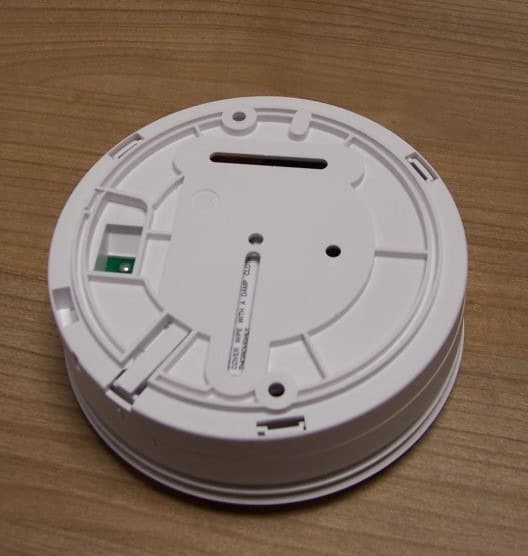
G2X-646041E
May 14, 2013312 Ei Smoke Alarm Model 64604/14
Equipment Class
DSC - Part 15 Security/Remote Control Transmitter
G2X-66004V
Dec 17, 201266004/09 iVi Personal Fall Detector.
Equipment Class
DXX - Part 15 Low Power Communication Device Transmitter
G2X-6360412
Dec 06, 201263604/12 Amie Personal Fall Alarm
Equipment Class
DXX - Part 15 Low Power Communication Device Transmitter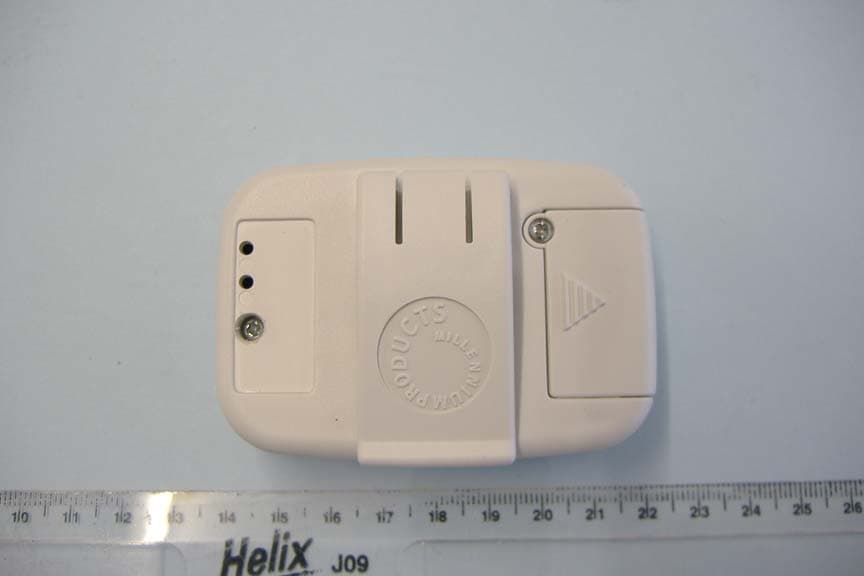
G2X66004
Jan 29, 2008312 Fall Detector
Equipment Class
DSC - Part 15 Security/Remote Control Transmitter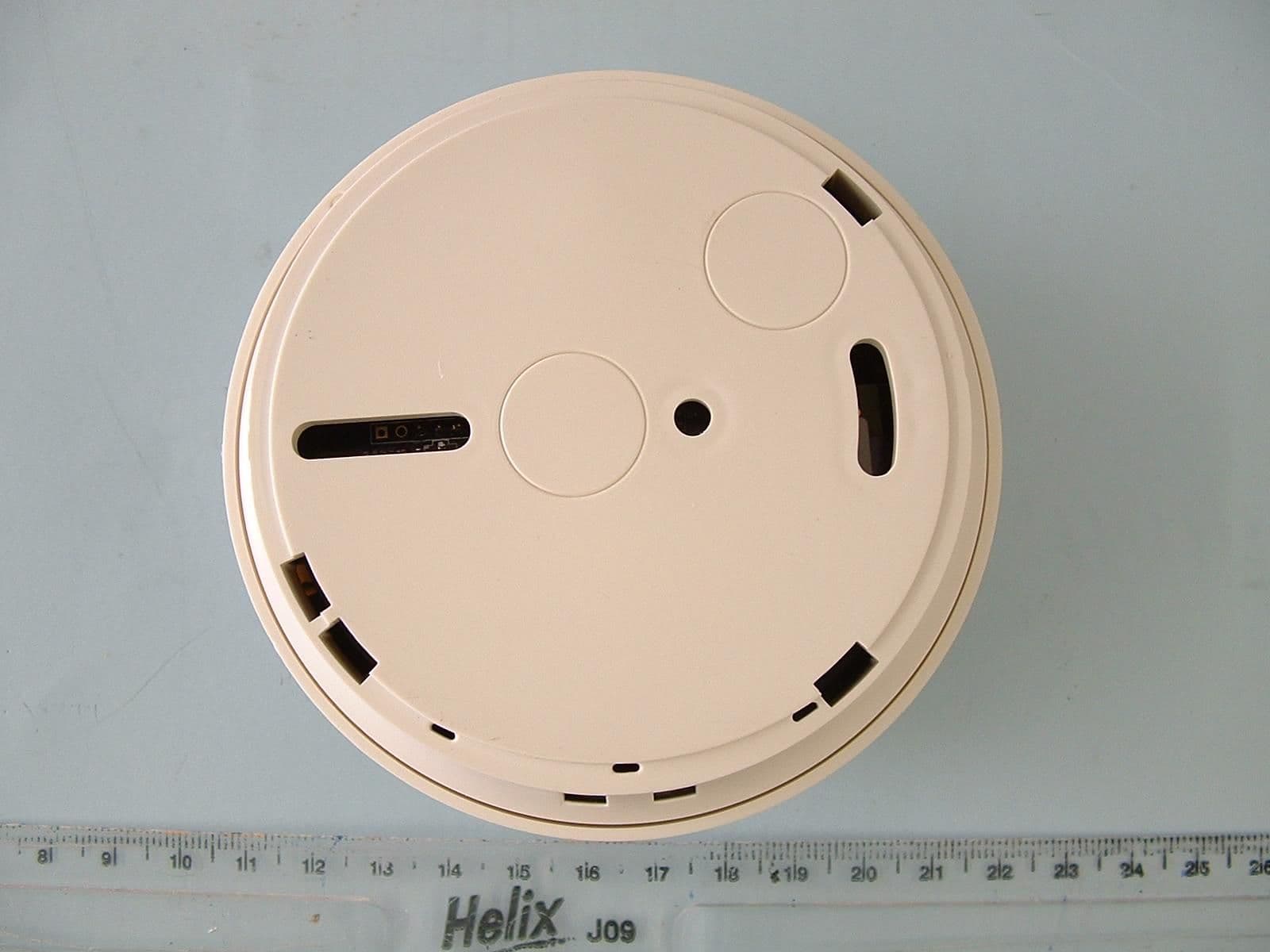
G2X-6460474A
Dec 15, 2006Radio Smoke Detector model 64604/74
Equipment Class
DSC - Part 15 Security/Remote Control Transmitter