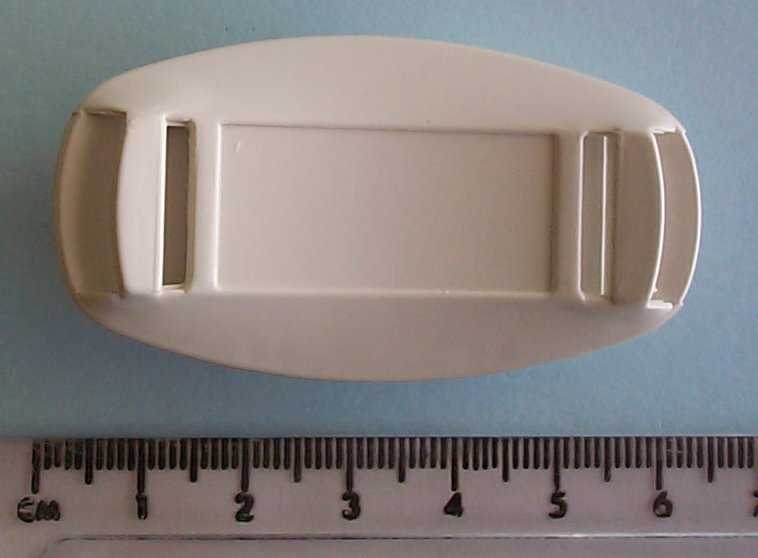
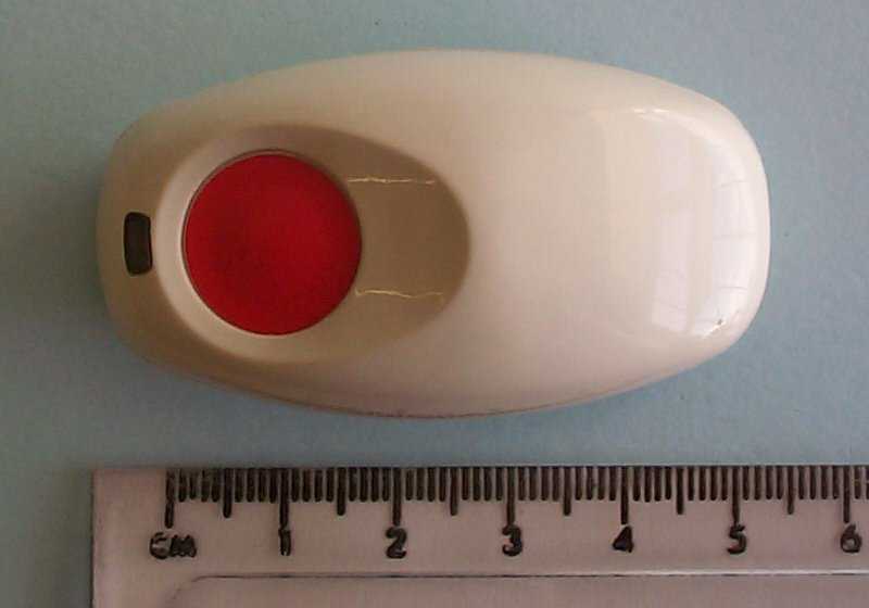
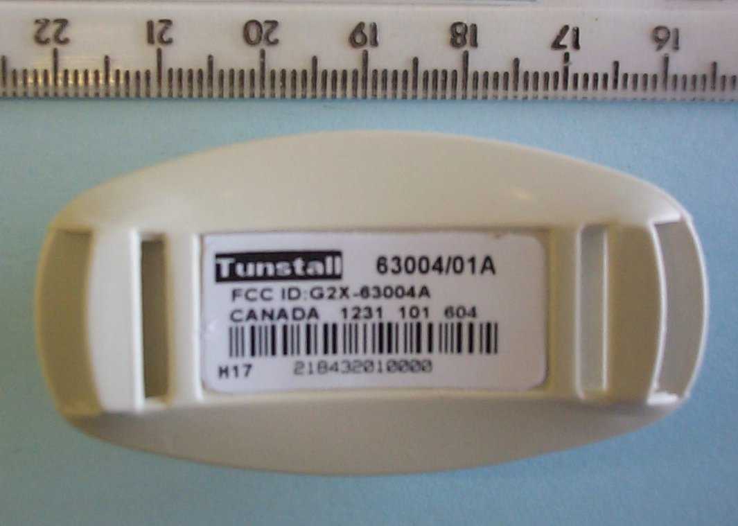
G2X63004AAmie Radio Pendant
Tunstall Healthcare (UK) Limited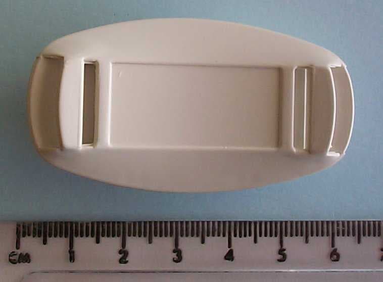
Click to zoom
Application Details
- Equipment Class
- DSC - Part 15 Security/Remote Control Transmitter
- Date of Grant
- May 20, 2003
- Application Purpose
- Original Equipment
- Date of Application
- May 20, 2003
- Equipment Note
- Amie Radio Pendant
- Frequency Range
- 312.00000000 - 312.00000000
- Country
- United Kingdom
Documents & Files
Document Text
Text extracted from the exhibit documents filed with the FCC. Open a document above to read the original.
Users Manual
Health Watch 9000 User Guide Part Number D3607105A Health Watch Inc, 777 Yamato Road, Suite 350, Boca Raton, FL33431. Tel. 1-800-226-8100 www.health-watch.com Contents Setting up1 Place HW 90001 Connect HW 90002 Test HW 90003 Using HW 90004 Requesting help4 Answering a call5 Making a call6 Adjusting the volume7 The Away feature8 Using medication reminders9 Using radio pendants10 Reliability11 Configuring HW 900012 Speed Dial Keys12 Voice Announcements14 Problems and Answers16 Copyright © 2002 All rights reserved. Neither the paper-based guide, nor the electronic version of the same, nor any portion of the text and/or images, may be copied, distributed, broadcast, or transmitted in any form or using any means howsoever, without the express written permis- sion, with the one exception described below. Under no circumstances may the paper-based or electronic guide be edited, amended or adapted, or used for any purpose other than as an aid to using HW 9000. Reproducing manuals for visually-impaired users This manual can be copied and enlarged to help visually-impaired users. Such copies may only be given to owners and users of HW 9000, and this is the only purpose for which anyone may reproduce this manual. You may enlarge this manual using a photocopier. Trade Marks TUNSTALL, AMIE, are trademarks of Tunstall Telecom Ltd HW 9000 User Guide1 Setting up Three simple steps 1.Place HW 9000 in a suitable position 2.Connect HW 9000 to your telephone line and a power outlet 3.Test HW 9000 by pressing the radio pendant to raise an alarm Although HW 9000 is a rather clever piece of equipment, it is quite robust, and you can treat it just like any other telephone. However, this means that you should not: • Place your HW 9000 next to something that makes a lot of noise, such as next to a television, radio or washing machine. •Put it right next to your oven, or close to any other heat source. •Set HW 9000 in a place where it will get damp, such as a bathroom, or near house plants that are sprayed at any time. •Place it very close to any large metal objects, such as microwave ovens, as large pieces of metal stop the signals from the radio pendant reaching HW 9000. •Put HW 9000 on top of something soft, such as a thick towel, as this can stop sound reaching the microphone. Place HW 9000 Place HW 9000 on a flat surface, or have it mounted on a wall. Put it somewhere you can easily reach. It should also be close to a telephone jack and a power outlet. Attaching to a wall. If you decide to attach your HW 9000 to a wall then you will find slots to grip the screws on the back of HW 9000. There is a separate paper template included in the packaging that will show you where to drill the holes for the screws. Note: As most users do not mount HW 9000 on the wall the screws needed for mounting are not provided. 2HW 9000 User Guide 2.You can then connect your ordinary telephone to HW 9000. If you do not connect your other telephones through HW 9000, but use a telephone adaptor instead, then HW 9000 may have difficulty making alarm calls if another telephone is being used for a call. 3. Next, connect the lead from the AC adapter to the back of your HW 9000, and then plug the AC adapter into a power outlet. Connect HW 9000 1.First, connect your HW 9000 to a telephone jack in your home using the cable that came in the box with HW 9000. Do not connect HW 9000 to the telephone jack via a telephone adaptor. HW 9000 User Guide3 4. When you connect your HW 9000 to the power the largest button on the top of your HW 9000 should light up. Test HW 9000 Once you have connected your HW 9000 you can test it. Press the button on the Amie pendant or Fall Detector that came with your HW 9000, and wait a few seconds. HW 9000 will call your response center. When your call is answered tell the operator that you are testing your new HW 9000—the operator will be pleased to hear from you. Problems? In the unlikely event that something does not work as you expect then consult the Problems and Answers section towards the back of this guide. 4HW 9000 User Guide Using HW 9000 Requesting help If you need help simply press the button on your Amie pendant (or Fall Detector). This sends a signal to HW 9000 which tells it to call your response center. Alternatively, if you can easily reach your HW 9000 you can press the large alarm button. (Your home can also be fitted with extra buttons and pull cords that raise an alarm. The person who installs these in your home will show you where they are and how they work). Cancelling If you accidentally raise an alarm call (i.e. you unintentionally press one of the alarm buttons on your HW 9000 or radio pendant) you can cancel the alarm call by waiting five seconds and then pressing your HW 9000’s Cancel key. However, once the call reaches a response center pressing the Cancel key will have no effect. This is a safety feature. When the operator answers your call simply explain that it was an error—the operator will be pleased to hear from you. HW 9000 User Guide5 Answering a call When the phone rings you can answer it in any of the four following ways: 1.Pick up the handset of the telephone attached to HW 9000. 2. Press the Speaker user key on the top of your HW 9000. This is the user key with Speaker displayed beside it. 3.Press the button on your Amie pen- dant (or Fall Detector). This method of answering a call can be turned off by an installer or your response center, and so you need to check that it has been set to work on your HW 9000. If you answer a call using your radio pendant you will only be able to carry on a hands-free conversation if you are close enough to hear and speak to your HW 9000. You can end the call by pressing the button on your radio pendant again. 4. Press the Cancel key on your HW 9000. Press the Cancel key again to end the call. 6HW 9000 User Guide Making a call You can make a call in the three following ways: 1. Press any of the Speed Dial keys on the top of your HW 9000. These…
Text truncated - open the document above for the full version.
Users Manual
Federal Communications Commission (FCC) notices This equipment complies with Part 68 of the FCC rules and the requirements adopted by the ACTA. On the base of this equipment is a label that contains, among other information, a product identifier in the format US:AAAEQ##TXXXX. If requested, this number must be provided to the telephone company. Universal Service order Code (USOC): RJ11C A plug and jack used to connect this equipment to the premises wiring and telephone network must comply with the applicable FCC Part 68 rules and requirements adopted by the ACTA. A compliant telephone cord and modular plug is provided with this product. It is designed to be connected to a compatible modular jack that is also compliant. See installation instructions for details. Ringer Equivalence Number (REN): 0.4 The REN is used to determine the number of devices that may be connected to a telephone line. Excessive RENs on a telephone line may result in the devices not ringing in response to an incoming call. In most but not all areas, the sum of RENs should not exceed five (5.0). To be certain of the number of devices that may be connected to a line, as determined by the total RENs, contact the local telephone company. For products approved after July 23, 2001, the REN for this product is part of the product identifier that has the format US:AAAEQ##TXXXX. The digits represented by ## are the REN without a decimal point (e.g., 04 is a REN of 0.4). For earlier products, the REN is separately shown on the label. If this equipment (HW3000 / HW6000 / HW9000) causes harm to the telephone network, the telephone company will notify you in advance that temporary discontinuance of service may be required. But if advance notice isn’t practical, the telephone company will notify the customer as soon as possible. Also, you will be advised of your right to file a complaint with the FCC if you believe it is necessary. The telephone company may make changes in its facilities, equipment, operations or procedures that could affect the operation of the equipment. If this happens the telephone company will provide advance notice in order for you to make necessary modifications to maintain uninterrupted service. This equipment (HW3000 / HW6000 / HW9000) contains no user serviceable parts. If trouble is experienced with this equipment (HW3000 / HW6000 / HW9000), for repair or warranty information, please contact HealthWatch Inc. Tel 1-800-226-8100. If the equipment is causing harm to the telephone network, the telephone company may request that you disconnect the equipment until the problem is resolved. Connection to party line service is subject to state tariffs. Contact the state public utility commission, public service commission or corporation commission for information. If your home has specially wired alarm equipment connected to the telephone line, ensure the installation of this equipment (HW3000 / HW6000 / HW9000) does not disable your alarm equipment. If you have questions about what will disable alarm equipment, consult your telephone company or a qualified installer. When programming emergency numbers and (or) making test calls to emergency numbers: Remain on the line and briefly explain to the dispatcher the reason for the call. Perform such activities in the off-peak hours, such as early morning or late evenings. Alarm dialing equipment must be able to seize the telephone line and place a call in an emergency situation. It must be able to do this even if other equipment (telephone, answering system, computer modem, etc.) already has the telephone line in use. To do so, alarm dialing equipment must be connected to a properly installed RJ31X jack that is electrically in series with and ahead of all other equipment attached to the same telephone line. Proper installation is depicted in the figure below. If you have any questions concerning these instructions, you should consult your telephone company or a qualified installer about installing the RJ31X jack and alarm dialing equipment for you. D3607107A - USER SUPPLEMENT HW3000 / HW6000 / HW9000 Network Service Provider’s Facilities Telephone Line Network Demarcation Point Telephone Answering System RJ31X Jack Alarm Dialling Equipment Unused RJ-11 Jack Computer Fax Machine Telephone Telephone Unused RJ-11 Jack Customer Premises Equipment and Wiring Federal Communications Commission (FCC) notices This equipment has been tested and found to comply with the limits for a Class B digital device, pursuant to part 15 of the FCC Rules. These limits are designed to provide reasonable protection against harmful interference in a residential installation. This equipment generates, uses and can radiate radio frequency energy and, if not installed and used in accordance with the instructions, may cause harmful interference to radio communications. However, there is no guarantee that interference will not occur in a particular installation. If this equipment does cause harmful interference to radio or television reception, which can be determined by turning the equipment off and on, the user is encouraged to try to correct the interference by one or more of the following measures: • Reorient or relocate the receiving antenna. • Increase the separation between the equipment and receiver. • Connect the equipment into an outlet on a circuit different from that to which the receiver is connected. • Consult the dealer or an experienced radio/TV technician for help. Industry Canada Notice This equipment meets the applicable Industry Canada Equipment Technical Specifications. This is confirmed by the registration number. The abbreviation, IC, before the registration number signifies that registration was performed based on a Declaration of Conformity indicating that Industry Canada technical specifications were met. It does not imply that Industry Canada approved the equipment. The Ringer Equivalence Number (REN) for this terminal equipment is 0.4. The REN assigned to each terminal eq…
Text truncated - open the document above for the full version.
Block Diagram
312 Amie Circuit Description Page 3 of 3 Block Diagram RG2Regulate TR4,5enable IC2Texas Processor Datashape Directfrequencyshift keyedcrystaloscillator-104MHz Frequencytripler to312MHz Integralantenna Tr3modulate
Cover Letter(s)
TRL 51F050 iss01 Request for Confidentiality 9 th April 2003 TRL Compliance Services Ltd Long Green Forthampton Gloucester GL19 4QH UK RE: Certification Application FCC ID: G2X-63004A To Whom It May Concern: Please be advised that the following information is to be held confidential on behalf of Tunstall Telecom Ltd. • Schematic Diagram • Circuit Description • Block Diagram The application contains technical information which, Tunstall Telecom Ltd deems to be trade secrets and propriety. If made public, the information might be used to the disadvantage of the applicant in the market place. Thank you for your attention to this matter. Yours faithfully Richard Nadin R&D Project Manager Tunstall Telecom Ltd Whitley Lodge, Whitley Bridge, Yorkshire, DN14 0HR Telephone: 01977 660398 Fax: 01977 660550 Website: www.tunstallgroup.com All the reassurance you need
Cover Letter(s)
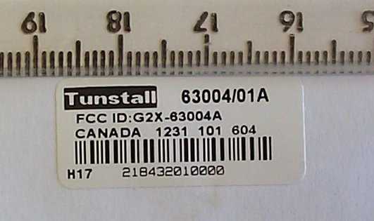
TRL 51F046 iss01 FCC Labelling Requirements and Information 9 th April 2003 TRL Compliance Services Ltd Long Green Forthampton Gloucester GL19 4QH UK RE: FCC Labelling Requirements FCC ID: G2X-63004A The following label information is required by the FCC Rules and Regulations for certified devices. Also attached, please find marketing information required by the FCC Rules and Regulations. Thank you for your attention to these matters. Yours faithfully Richard Nadin R&D Project Manager Tunstall Telecom Ltd Whitley Lodge, Whitley Bridge, Yorkshire, DN14 0HR Telephone: 01977 660398 Fax: 01977 660550 Website: www.tunstallgroup.com All the reassurance you need
Cover Letter(s)
TRL 51F047 iss02 Letter of Agency 21 st March 2003 TRL Compliance Services Ltd Long Green Forthampton Gloucester GL19 4QH UK To Whom It May Concern: We certify that we are not subject to denial of federal benefits, that includes FCC benefits, pursuant to Section 5301 of the Anti-Drug Abuse ACT of 1988, U.S.C. 862. Further, no party, as defined in 47 CFR 1.2002(b), to the application is subject to denial of federal benefits, that includes FCC benefits. Thank you for your attention to this matter. Yours faithfully Richard Nadin R&D Project Manager Tunstall Telecom Ltd Whitley Lodge, Whitley Bridge, Yorkshire, DN14 0HR Telephone: 01977 660398 Fax: 01977 660550 Website: www.tunstallgroup.com All the reassurance you need
Cover Letter(s)
TRL 51F048 iss01 Manufacturer’s Letter 9 th April 2003 TRL Compliance Services Ltd Long Green Forthampton Gloucester GL19 4QH UK RE: FCC Labelling Requirements FCC ID: G2X-63004A To Whom It May Concern: Please be advised that the manufacturer will ensure that the above-referenced model will be manufactured in accordance with the FCC Rules and Regulations. Thank you for your attention to this matter. Yours faithfully Richard Nadin R&D Project Manager Tunstall Telecom Ltd Whitley Lodge, Whitley Bridge, Yorkshire, DN14 0HR Telephone: 01977 660398 Fax: 01977 660550 Website: www.tunstallgroup.com All the reassurance you need
Parts List/Tune Up Info
Part NumberDescription D6302012EBACK MLDNG (ABS) AMIE D6302022EFRONT MLDNG (AMIE POLAR) D6304103AO RING SEAL D6307413BLOW FORCE FASCIA (AMIE) E340FLEXCOM WHITE GLOSS LABEL NOT FITTEDNO COMPONENT FITTED SA6330AMIE 312MHz NO ASIC,28bit prog D6300014ABattery Pack non asic amie E402BLANK LABEL 30.2 * 12.7 D0007343ASTICKY PAD 6x6x1mm
Parts List/Tune Up Info
CCT RefPart NumberDescription ANT001D6303013AANTENNA PIN (D08 C01S1263272CAP 2n7F 50V 10% X7R 0603 C02S1262471CAP 470pF 50V 5% COG 0603 C03S1262150CAP 15pF 50V 5% COG 0603 C04S1262120CAP 12pF 50V 5% COG 0603 C05S1262101CAP 100pF 50V 5% COG 0603 C06S1262471CAP 470pF 50V 5% COG 0603 C07S1263272CAP 2n7F 50V 10% X7R 0603 C08S1262270CAP 27pF 50V 5% COG 0603 C09S1262270CAP 27pF 50V 5% COG 0603 C10S1262033CAP 3p3F 50V +/- 0p25 COG 0603 C11S1262056CAP 5p6F 50V +/- 0p25 COG 0603 C12S1262101CAP 100pF 50V 5% COG 0603 C14S1263272CAP 2n7F 50V 10% X7R 0603 C15S1256001CAP 100nF 16V +80-20% Y5V 0603 C16S1263224CAP 220nF 10V 10% X7R 0603 C17S1256001CAP 100nF 16V +80-20% Y5V 0603 C18S1256001CAP 100nF 16V +80-20% Y5V 0603 C19S1252027CAP 1u5F 16V -20+80% Y5V 1206 C20S1256001CAP 100nF 16V +80-20% Y5V 0603 D1S1355001VARICAP DIODE 1SV223 T&R D2S1350005LED RED HIGH BRIGHTNESS IC2S1666000IC Microcontroller MSP430F1121 L1S1551034INDUCTOR 100nH 5% (TDK) 1210 L2S1551030INDUCTOR 68nH 5% (TDK) 1210 L3S1551033INDUCTOR 330nH 5% (TDK) 1210 L4S1551030INDUCTOR 68nH 5% (TDK) 1210 L5S1551037INDUCTOR 39nH 5% (TDK) 1210 LABELD6307623AAmie (Non Asic) Unprog PCBD6301036DAmie UHF PCB (Non ASIC) R01S1160103RESISTOR 10K 1% 0W063 0603 R02S1160273RESISTOR 27K 1% 0W063 0603 R03S1160101RESISTOR 100R 1% 0W063 0603 R04S1160222RESISTOR 2K2 1% 0W063 0603 R05S1160151RESISTOR 150R 1% 0W063 0603 R06S1160472RESISTOR 4K7 1% 0W063 0603 R07NOT FITTEDNO COMPONENT FITTED R08S1160101RESISTOR 100R 1% 0W063 0603 R10S1160153RESISTOR 15K 1% 0W063 0603 R11S1160104RESISTOR 100K 1% 0W063 0603 R13S1160153RESISTOR 15K 1% 0W063 0603 R14S1160104RESISTOR 100K 1% 0W063 0603 R15S1160472RESISTOR 4K7 1% 0W063 0603 R16S1160153RESISTOR 15K 1% 0W063 0603 R17S1160682RESISTOR 6K8 1% 0W063 0603 R18S1160391RESISTOR 390R 1% 0W063 0603 R19S1160271RESISTOR 270R 1% 0W063 0603 R21NOT FITTEDNO COMPONENT FITTED R22S1160000RESISTOR 0R 1% 0W063 0603 R23S1160184RESISTOR 180K 1% 0W063 0603 R24S1160154RESISTOR 150K 1% 0W063 0603 R27S1160153RESISTOR 15K 1% 0W063 0603 R28S1160154RESISTOR 150K 1% 0W063 0603 R29S1160153RESISTOR 15K 1% 0W063 0603 R30S1160153RESISTOR 15K 1% 0W063 0603 RG1NOT FITTEDNO COMPONENT FITTED RG2S1751017Regulator 4V sot23-5 SW1S2550001SWITCH SMD TACTILE TH1NOT FITTEDNO COMPONENT FITTED TR1S1451045TRANSISTOR FMMT918 TR2S1451046TRANSISTOR BFS17P NPN TR3S1460000Transistor BC847 NPN SOT416 TR4S1460000Transistor BC847 NPN SOT416 TR5S1460001Transistor BC857 PNP SOT416 VC1S1259015CAP 3-10pF VARIABLE VR1S1155008POTENTIOMETER 4K7 TRIMMER SMD VR2S1155008POTENTIOMETER 4K7 TRIMMER SMD XT1S1901021CRYSTAL 104.0000MHz. XT2S1952015CRYSTAL 32.768KHz watch 869ami
Test Report
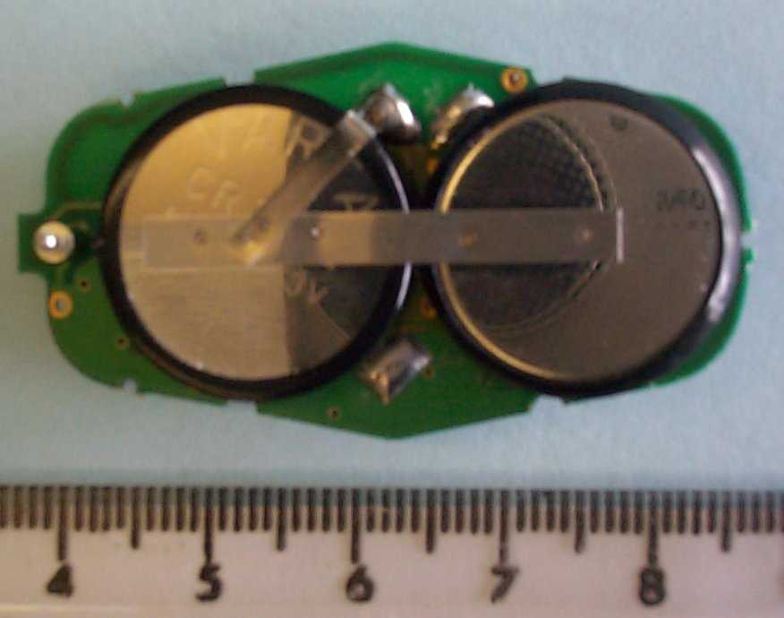
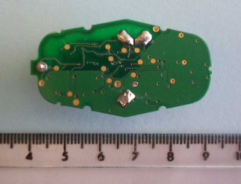
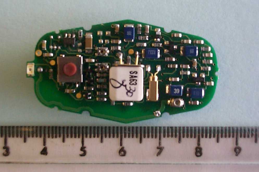
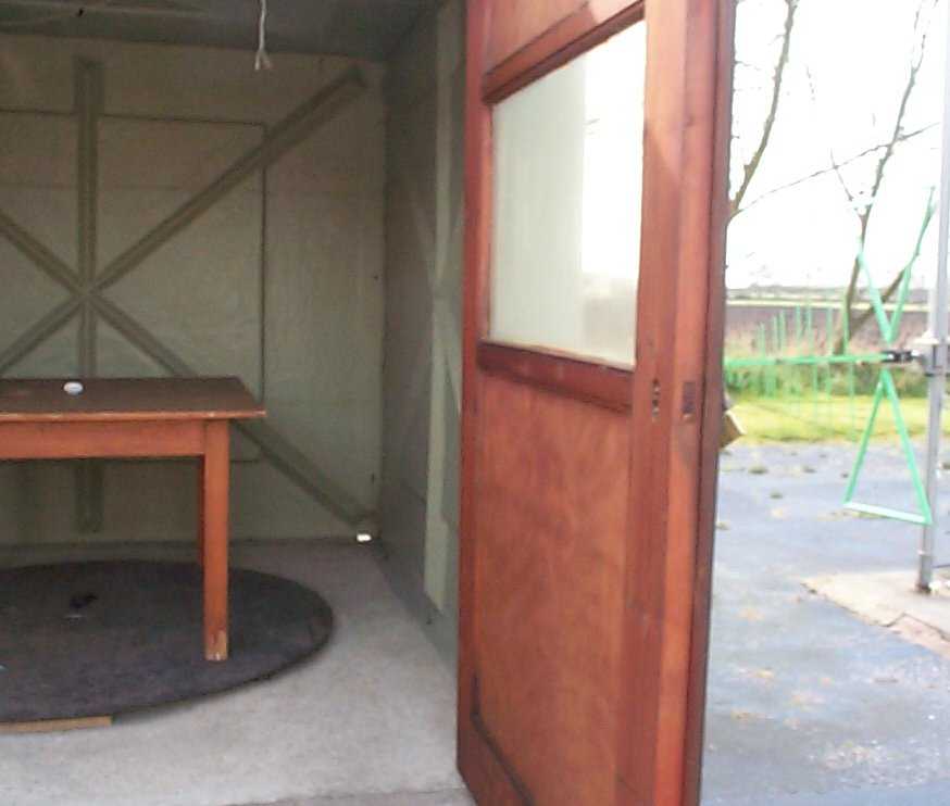
TRL C OMPLIANCE S ERVICES L TD EMC DIVISION LONG GREEN FORTHAMPTON GLOUCESTER GL19 4QH UNITED KINGDOM TELEPHONE +44 (0)1684 833818 FAX +44 (0)1684 833858 E- MAIL [email protected] www.trlcompliance.com 0728 TEST REPORT NO:RU1051/4303 COPY NO:1 ISSUE NO:1 FCC ID:G2X 63004A REPORT ON THE CERTIFICATION TESTING OF A TUNSTALL TELECOM Ltd. AMIE RADIO TRANSMITTER WITH RESPECT TO THE FCC RULES CFR 47, PART 15.231 INTENTIONAL RADIATOR SPECIFICATION TEST DATE: 15 th – 22 nd April 2003 TESTED BY:J CHARTERS APPROVED BY:P GREEN PRODUCT MANAGER DATE:2 nd May 2003 Distribution: Copy Nos:1.TUNSTALL TELECOM Ltd. 2.FCC EVALUATION LABORATORIES 3.TRL EMC THIS DOCUMENT MAY BE REPRODUCED ONLY IN ITS ENTIRETY AND WITHOUT CHANGE RF335 iss02RU1051/4303Page 2 of 24 CONTENTS PAGE CERTIFICATE OF CONFORMITY & COMPLIANCE3 APPLICANT’S SUMMARY4 EQUIPMENT TEST CONDITIONS5 TESTS REQUIRED5 SAMPLE CALCULATIONS6 TEST RESULTS6-9 ANNEX PHOTOGRAPHSA PHOTOGRAPH No. 1: Test setup PHOTOGRAPH No. 2: Transmitter front view PHOTOGRAPH No. 3: Transmitter rear view PHOTOGRAPH No. 4: Transmitter PCB track side PHOTOGRAPH No. 5: Transmitter PCB component side PHOTOGRAPH No. 6: Transmitter PCB track side with battery APPLICANT’S SUBMISSION OF DOCUMENTATION LISTB BAND OCCUPANCY PLOTC TRANSMITTER ON TIMED Notes: 1.Component failure during testYES NO [ ] [X] 2.If Yes, details of failure: 3.The facilities used for the testing of the product contain in this report are FCC Listed. 4.The contents of the attached applicants declarations and other supplied information are not covered by the scope of this laboratory’s UKAS or FCC accreditations’ and is provided in good faith. RF335 iss02RU1051/4303Page 3 of 24 CERTIFICATE OF CONFORMITY & COMPLIANCE FCC IDENTITY:G2X 63004A PURPOSE OF TEST:Certification TEST SPECIFICATION:FCC RULES CFR 47, Part 15.231 TEST RESULT:Compliant to Specification EQUIPMENT UNDER TEST:AMIE RADIO TRANSMITTER EQUIPMENT SERIAL No:Engineering sample ITU: EMISSION CODE:3k00F1DAN EQUIPMENT TYPE:63004 PRODUCT USE:Fall Alarm CARRIER EMISSION: 1678.8μV/m @3m ANTENNA TYPE:Integral ALTERNATIVE ANTENNA:N/A BAND OF OPERATION:260MHz-470MHz CHANNEL SPACING:N/A NUMBER OF CHANNELS:1 FREQUENCY GENERATION:SAW Resonator[ ]Crystal[X]Synthesiser [ ] MODULATION METHOD:Amplitude[ ]Digital[X]Angle [ ] POWER SOURCE(s):6Vdc TEST DATE(s): 15 th – 22 nd April 2003 ORDER No(s):10543 APPLICANT:TUNSTALL TELECOM Ltd. ADDRESS:Whitley Lodge Whitley Bridge Yorkshire United Kingdom DN14 0HR TESTED BY:J CHARTERS APPROVED BY:P GREEN PRODUCT MANAGER RF335 iss02RU1051/4303Page 4 of 24 APPLICANT’S SUMMARY EQUIPMENT UNDER TEST (EUT):AMIE RADIO TRANSMITTER EQUIPMENT TYPE:63004 SERIAL NUMBER OF EUT:Engineering sample PURPOSE OF TEST:Certification TEST SPECIFICATION(s):FCC RULES CFR 47, Part 15.231 TEST RESULT:COMPLIANTYes No [X] [ ] APPLICANT’S CATEGORY:MANUFACTURER IMPORTER DISTRIBUTOR TEST HOUSE AGENT [X] [ ] [ ] [ ] [ ] APPLICANT’S ORDER No(s):10543 APPLICANT’S CONTACT PERSON(s):Mr Richard Nadin E-mail address: [email protected] APPLICANT:TUNSTALL TELECOM Ltd. ADDRESS:Whitley Lodge Whitley Bridge Doncaster DN14 0HR United Kingdom TEL:01977 661234 FAX:01977 662570 MANUFACTURER:TUNSTALL TELECOM Ltd. EUT(s) COUNTRY OF ORIGIN:United Kingdom TEST LABORATORY:TRL EMC UKAS ACCREDITATION No:0728 TEST DATE(s) 15 th – 22 nd April 2003 TEST REPORT No:RU1051/4303 RF335 iss02RU1051/4303Page 5 of 24 EQUIPMENT TEST / EXAMINATIONS REQUIRED 1. TEST/EXAMINATIONRULE PARTDETECTORAPPLICABILITY Intentional Emission Frequency:15.231Quasi PeakYes Intentional Emission Field Strength:15.231(b)Quasi PeakYes Intentional Emission Band Occupancy:15.231(c)Quasi PeakYes Intentional Emission ERP (mW):--No Spurious Emissions – Conducted:15.207-No Spurious Emissions – Radiated <1000MHz: 15.209 15.231(b) Quasi Peak Average Yes Spurious Emissions – Radiated >1000MHz: 15.209 15.231(b) Average Average Yes Maximum Frequency of Search:15.33-Yes Antenna Arrangements Integral:15.203-Yes Antenna Arrangements External Connector:15.204-Yes Restricted Bands15.205-Yes Extrapolation Factor15.31(f)-Yes 2.Product Use:Fall Alarm 3.Emission Designator:3K00F1DAN 4.Duty Cycle:<1% 5.Transmitter bit or pulse rate and level:20 Bps 6.Temperatures:Ambient (Tnom)20 o C 7.Supply Voltages:Vnom2x3V lithium cells Note: Vnom voltages are as stated above unless otherwise shown on the test report page Single channel[X] Two channel[ ] 8.Equipment Category: Multi-channel[ ] Narrowband[ ] Wideband[X] 9.Channel spacing: RF335 iss02RU1051/4303Page 6 of 24 TRANSMITTER TESTS TRANSMITTER SPURIOUS EMISSIONS – RADIATED – PART 15.209 Ambient temperature=20 o C(<1GHz)3m measurements <1GHz[X] Relative humidity=54% (<1GHz),0.3m measurements >1GHz[X] Conditions=Open Area Test Site (OATS)3m extrapolated from 0.3m[X] Supply voltage=6Vdc Channel number=1 FREQ. (MHz) MEAS. Rx. (dBμV) CABLE LOSS (dB) ANT FACTOR FIELD STRENGTH (dBμV/m) EXTRAP. FACTOR (dB) FIELD STRENGTH (μV/m) LIMIT (μV/m) 30MHz- 88MHz 88MHz-216MHz104.014.610.611.026.21-20.4500 216MHz-960MHz 960MHz-1GHz 1GHz-5GHz 1560.0(R) 1872.0 2184.0 30.6 41.6 36.9 0.2 0.2 0.3 25.7 26.8 28.0 56.5 68.6 65.2 20 20 20 66.8 269.1 181.9 500 588 588 1.705MHz to 30MHz 30μV/m@ 30m 30MHz to 88MHz100μV/m@ 3m 88MHz to 216MHz150μV/m@ 3m 216MHz to 960MHz200μV/m@ 3m 960MHz to 1GHz500μV/m@ 3m Limits 1GHz to 5GHz500μV/m@ 3m Notes: 1Results quoted are extrapolated as indicated 2 Emissions were searched to: (x) 1000MHz inclusive, as per Part 15.33a 3Extrapolation factor 9.5dB from 1m to 3m, as per Part 15.31f 4Measurements >1GHz @ 1m as per Part 15.31f(1) 5Receiver detector >1GHz = CISPR, Quasi-Peak, 120kHz bandwidth 6Receiver detector >1GHz = Peak Hold, 1MHz resolution bandwidth 7New batteries used for battery powered products. 8(R) indicated frequency within restricted band from 15.205 9Due to the transmitted signal lasting only 1.1 second. A unit with modified software which allowed continuos transmission was used during spurious emissions testing. Test Method: 1As per Radio – Noise Emissions, ANSI C63.4:…
Text truncated - open the document above for the full version.
Contact Information
Applicant
Mark Jennings(Chief Engineer)
Technical Contact
Tunstall Telecom LimitedRichard Martin
[email protected]44 1977 661234
Whitley Lodge · Doncaster · United Kingdom
Test Firm
TRL EMC LimitedNeil Roche
Technical Specifications
| # | Rule Parts | Frequency Range | Power Output |
|---|---|---|---|
| 1 | 15.231 | 312 MHz - 312 MHz | - |
Other Applications from Tunstall Healthcare (UK) Limited
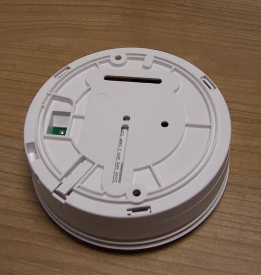
G2X-646041E
May 14, 2013312 Ei Smoke Alarm Model 64604/14
Equipment Class
DSC - Part 15 Security/Remote Control Transmitter
G2X-66004V
Dec 17, 201266004/09 iVi Personal Fall Detector.
Equipment Class
DXX - Part 15 Low Power Communication Device Transmitter
G2X-6360412
Dec 06, 201263604/12 Amie Personal Fall Alarm
Equipment Class
DXX - Part 15 Low Power Communication Device Transmitter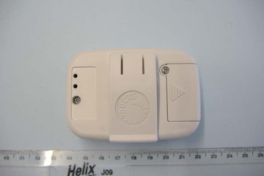
G2X66004
Jan 29, 2008312 Fall Detector
Equipment Class
DSC - Part 15 Security/Remote Control Transmitter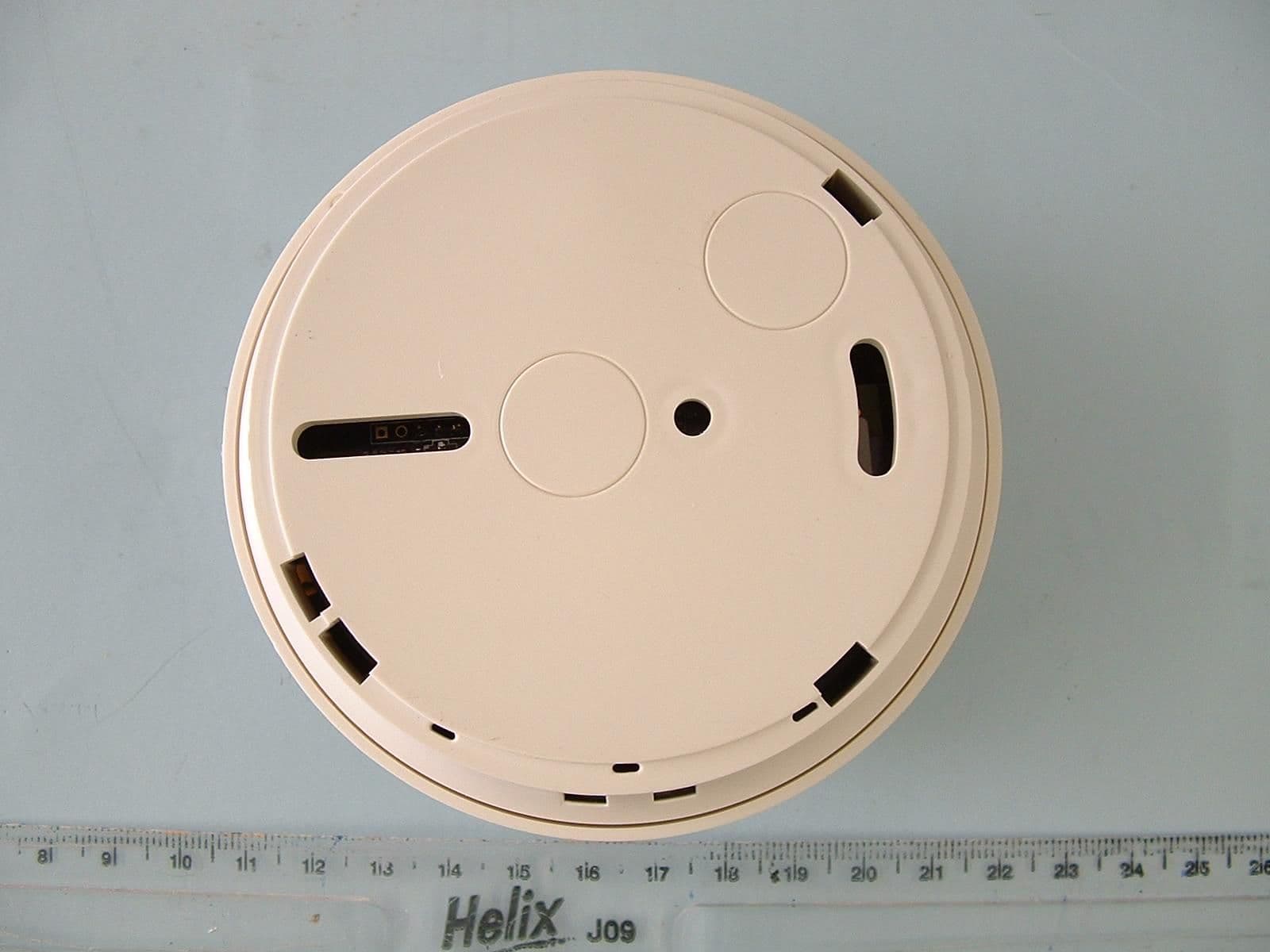
G2X-6460474A
Dec 15, 2006Radio Smoke Detector model 64604/74
Equipment Class
DSC - Part 15 Security/Remote Control Transmitter