GL7AI50Class B AIS transponder
Navico UK Ltd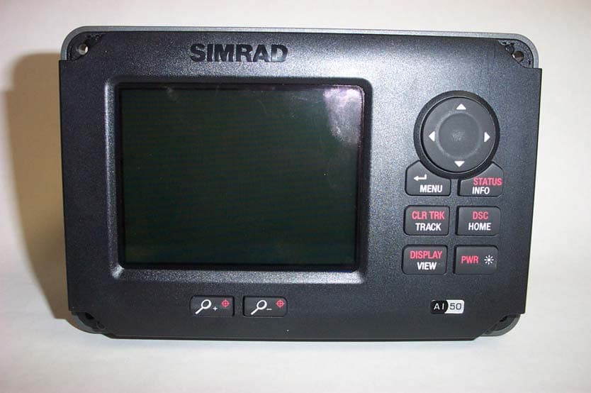
Click to zoom
Application Details
- Equipment Class
- AIS - Automatic Identification Systems
- Date of Grant
- Oct 02, 2008
- Application Purpose
- Original Equipment
- Date of Application
- Sep 27, 2007
- Equipment Note
- Class B AIS transponder
- Frequency Range
- 156.52500000 - 162.52500000
- Company
- Navico UK Ltd
- Country
- United Kingdom
Documents & Files
Document Text
Text extracted from the exhibit documents filed with the FCC. Open a document above to read the original.
Users Manual
MANUAL Simrad AI50 Class B Transceiver 988-0168-001 May07 English MANUAL Simrad AI50 Class B Transceiver 988-0168-002 Iss.2.0 English The technical data, information and illustrations contained in this publication were to the best of our knowledge correct at the time of going to print. We reserve the right to change specifi cations, equipment, installation and maintenance instructions without notice as part of our policy of continuous development and improvement. No part of this publication may be reproduced, stored in a retrieval system or transmitted in any form, electronic or otherwise, without prior permission from Simrad Ltd. No liability can be accepted for any inaccuracies or omissions in the publication, although every care has been taken to make it as complete and accurate as possible. © 2007 Navico 988-0168-001 Iss.2.0 May 07 WP Contents V AIS50 CLASS B TRANCEIVER CONTENTS 1 INTRODUCTION 1.1 General Overview 9 1.2 About this manual 10 1.3 SimNet/NMEA2000 Network System 10 2 INSTALLATION 2.1 General 11 2.2 Panel Mounting 11 2.3 Bracket Mounting 12 2.4 GPS Antenna 12 2.5 VHF Antenna 13 2.6 Power/Data Cable 15 2.7 SimNet Cable 15 2.8 SD card (Not supplied) 16 3 KEYPAD OVERVIEW 3.1 Layout 17 3.2 PWR/Lights key (Powering on and off) 17 3.3 Navigation Keys 18 3.3.1 Display Mode 18 3.3.2 Menu Mode 18 3.3.3 Data Entry Mode 18 3.4 Zoom Keys 18 3.5 ENTER/MENU 18 3.6 INFO/STATUS 19 3.7 TRACK/CLR TRK 19 3.8 HOME/DSC 19 3.9 VIEW/DISPLAY 19 3.10 PWR/ (Backlight adjustment) 19 4 INITIAL CONFIGURATION 4.1 Window Display convention 21 4.2 Initial Start Up Sequence 21 4.3 Ship Confi guration Procedure 23 4.3.1 MMSI Entry 23 4.3.2 Vessel Type Entry 25 4.3.3 Vessel Dimensions & GPS Reference 26 AIS Class B Transceiver VI 4.3.4 Call Sign Entry 27 4.3.5 Vessel Name Entry 28 5 MENU MODE 5.1 General 29 5.2 Display Mode settings 29 5.2.1 Coastline Detail 29 5.2.2 Tracking Offset 30 5.2.3 Display Offset 30 5.2.4 Show Range Rings 31 5.3 Display Settings 31 5.3.1 Display Brightness 31 5.3.2 Keypad Brightness 32 5.3.3 Keypad Colour 32 5.3.4 Display Palette 32 5.4 Favourites List 33 5.4.1 Add an Entry 33 5.4.2 Edit an Entry 34 5.4.3 Delete an Entry 35 5.5 Alarm Setup 35 5.5.1 Collision Alarm 36 5.5.1.1 CPA/TCPA 36 5.5.1.2 Guard Zone 37 5.5.2 Lost Vessel Alarm 38 5.5.3 Favourites Alarm 39 5.6 System Setup 40 5.6.1 Units of Measure 40 5.6.2 Set Local Time 41 5.6.3 Ship Confi guration 41 5.6.4 Key Beeps 42 5.6.5 Set Language 42 5.6.6 Data Logging 42 5.6.6.1 Enabling 43 5.6.6.2 Disabling 44 5.6.6.3 Playback Log 44 5.6.7 Transmit Enable 45 5.6.8 Reset Options 45 5.7 SimNet/NMEA2000 45 5.7.1 Data Sources 46 5.7.2 Network Management 46 Contents VII 5.7.2.1 Device Instance 46 5.7.2.2 System Instance 47 5.7.3 Network List 47 5.7.4 Remote Enable 48 5.7.4 DSC Radio Select 48 5.8 Product Info 48 6 AIS MAP MODE 6.1 General 51 6.2 Vessel Icon Detail 51 6.3 Range Rings/ Range Info 51 6.4 Point Of View 52 6.5 Coast Line Detail 54 6.6 Cursor 54 6.7 Transmit Legend 54 6.8 Vessel Information 55 6.8.1 Own Vessel 55 6.8.2 Other Vessel’s Info (Reduced list) 55 6.8.3 Other Vessel (Full list) 56 6.8.4 Other Vessel (Minimal list) 56 6.9 General Rules for Vessel Information 57 6.10 Making a DSC Call (in map mode) 57 6.11 Text Mode 58 6.11.1 Changing the Sort Order 59 6.12 Making a DSC Call (in text mode) 59 6.13 Tracking Individual Vessels 59 6.14 Tracking your own Vessel 60 6.15 Clearing Down All Trails 60 6.16 Light Adjustment (Short Cut) 61 7 ALARMS 7.1 General 63 7.2 Collision Alarm – CPA/TCPA 64 7.3 Collision Alarm – Lost Vessel 65 7.4 Collision Alarm – Guard Zone 66 7.5 BIIT Alarm 66 7.6 Lost Vessel Alarm 67 7.7 Favourites Alarm 67 7.8 Loss Of Compass Heading Data 68 7.9 Safety Message Alarm 69 AIS Class B Transceiver VIII 8 APPENDIX 8.1 Maintenance 71 8.2 Troubleshooting 71 8.3 Accessories 72 8.4 Product Specifi cations 72 8.5 Dimensions 74 8.6 Service and Warranty 74 8.7 Declaration of Conformity (EU) 75 Introduction 9 1 INTRODUCTION 1.1 General Overview Simrad’s AI50 is an Automatic Identifi cation System (AIS). It is an autonomous and continuous information reporting system, operating in the VHF maritime mobile band. It allows AIS equipped vessels to automatically and dynamically exchange and display information with similarly equipped vessels and shore based traffi c stations. Fig. 1.1 The AI50 uses a sophisticated automatic digital time sharing technology which allows a large number of similarly equipped vessels within VHF range of each other, to time share the same radio channel without interference. This enables the automatic exchange of static information like; MMSI (Maritime Mobile Service Identifi er) Number, Vessel’s Name, Call Sign and Type. Also dynamic data like; Position, Course, Distance and more, from ship to ship, and from ship to shore based traffi c stations. The advantages of the AI50 are: Increased awareness of the current shipping situation within your VHF range through the exchange of data between vessels. Improving traffi c management in busy shipping lanes through exchanging information between vessels and shore based traffi c stations. • • Fig. 1.1 - AI50 Class B Transceiver AIS Class B Transceiver 10 Reporting information automatically in shipping areas where it is mandatory. WARNING As with all electronic navigational equipment, it is only an aid to navigation and should not be used as a substitute for good seamanship. Remember - Maritime law requires that you keep a good lookout at all times. The position of a vessel on the screen is the position of the most recent transmission and may not be the current position. 1.2 About this manual The manual combines operating and installation information for the AI50. Operation is sub-divided into main working categories for easy reference. 1.3 SimNet/NMEA2000 Network System SimNet is Simrad’s proprietary high speed data bus network complete with NMEA2000. It provides intelligent sharing of data and control information between a wide range of marine electro…
Text truncated - open the document above for the full version.
External Photos
Navico UK Ltd, Unit 4, Ocivan Way, Margate, Kent, CT9 4NN, United Kingdom Tel +44 1843 290290 Fax +44 1843 232903 External Pictures of the Simrad AI50 Class B transponder Figure 1: Front view of the Simrad AI50 Figure 2: Rear View of the Simrad AI50 Navico UK Ltd, Unit 4, Ocivan Way, Margate, Kent, CT9 4NN, United Kingdom Tel +44 1843 290290 Fax +44 1843 232903 Figure 3: Right hand side view of the Simrad AI50 Figure 4: Left hand view of the Simrad AI50 Note: mounting bracket omitted for clarity.
ID Label/Location Info
Navico UK Ltd, Unit 4, Ocivan Way, Margate, Kent, CT9 4NN, United Kingdom Tel +44 1843 290290 Fax +44 1843 232903 Label information and lo c a ti o n of the Simrad AI50 Figure 1: Position of ID label on rear of unit Figure 2: Detail of ID label
ID Label/Location Info
The following label will be added to the AI50. It is to be fitted to the top of the unit, so it is seen by the user when they open the packaging as indicated in the picture below. FOR USERS IN THE UNITED STATES OF AMERICA ONLY WARNING: It is a violation of the rules of the Federal Communications Commission to input an MMSI that has not been properly assigned to the end user, or to otherwise input any inaccurate data in this device. The MMSI and Static Data must be entered by the vendor of the device or by an appropriately qualified person in the business of installing marine communications equipment on board vessels Instructions for entering the MMSI and static data, including the vessels name, call sign, dimensions and type can be found in the user manual supplied with this unit. Further details may also be found on the CD. ©Navico Part number here
Internal Photos
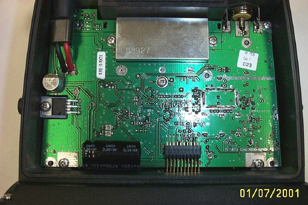
Navico UK Ltd, Unit 4, Ocivan Way, Margate, Kent, CT9 4NN, United Kingdom Tel +44 1843 290290 Fax +44 1843 232903 Internal Photos of the Simrad AI50 Figure 1: RF PCB; This is the SRT PCB licensed to Navico Figure 2: Control PCB in situ with screen Navico UK Ltd, Unit 4, Ocivan Way, Margate, Kent, CT9 4NN, United Kingdom Tel +44 1843 290290 Fax +44 1843 232903 Figure 3: Control PCB Figure 4: Control PCB showing interconnects Navico UK Ltd, Unit 4, Ocivan Way, Margate, Kent, CT9 4NN, United Kingdom Tel +44 1843 290290 Fax +44 1843 232903 Figure 5: Interior of rear case showing external connector PCB
Internal Photos
Navico UK Ltd, Unit 4, Ocivan Way, Margate, Kent, CT9 4NN, United Kingdom Tel +44 1843 290290 Fax +44 1843 232903 Internal Photos of the Simrad AI50 Figure 1: RF PCB DSP side; (this is the SRT PCB licensed to Navico) Figure 2: RF PCB DSP side with screens removed Navico UK Ltd, Unit 4, Ocivan Way, Margate, Kent, CT9 4NN, United Kingdom Tel +44 1843 290290 Fax +44 1843 232903 Figure 3: RF PCB FPGA side with screens removed Navico UK Ltd, Unit 4, Ocivan Way, Margate, Kent, CT9 4NN, United Kingdom Tel +44 1843 290290 Fax +44 1843 232903 Figure 4: Control PCB in situ with screen removed Figure 5: Control PCB in situ with overall screen removed Navico UK Ltd, Unit 4, Ocivan Way, Margate, Kent, CT9 4NN, United Kingdom Tel +44 1843 290290 Fax +44 1843 232903 Figure 6: Control PCB with local screens removed Figure 7: Control PCB keypad side with local screen removed Navico UK Ltd, Unit 4, Ocivan Way, Margate, Kent, CT9 4NN, United Kingdom Tel +44 1843 290290 Fax +44 1843 232903 Figure 8: Control PCB in conjunction with LCD and front panel. Figure 9: Control PCB showing interconnects Navico UK Ltd, Unit 4, Ocivan Way, Margate, Kent, CT9 4NN, United Kingdom Tel +44 1843 290290 Fax +44 1843 232903 Figure 10: Interior of rear case showing external connector PCB
Test Report
Bundesrepublik Deutschland Federal Republic of Germany Bundesamt für Seeschifffahrt und Hydrographie Federal Maritime and Hydrographic Agency nach DIN EN 17025 akkreditiertes Prüflaboratorium Federal Maritime and Hydrographic Agency Bernhard-Nocht-Str. 78 D-20359 Hamburg Germany DAT-P-086/98-01 Note: Extracts from this test report shall not be copied without permission of the Federal Maritime and Hydrographic Agency Version 2.0 Conformance test report of an AIS system Equipment under test:SRT Type:SRT-MTB-OEM Applying test standards: IEC 62287Sections 10,12,13, Annex C.3 Test Report No.:BSH/46162/4320358/06/S3140 Applicant:Software Radio Technology Wireless House, First Avenue, Midsomer Norton, Bath, BA3 ABS United Kingdom Hamburg, 08 September 06 Federal Maritime and Hydrographic Agency by orderby order BartelsPreuss Test engineerhead of laboratory Bundesamt für Seeschifffahrt und Hydrographie Federal Maritime and Hydrographic Agency Test Report No.. BSH/46162/4320358/06/S3140Date: 08.09.2006page 3 of 116 Bundesamt für Seeschifffahrt und Hydrographie Federal Maritime and Hydrographic Agency Test Report No.. BSH/46162/4320358/06/S3140Date: 08.09.2006page 4 of 116 General Applicant:Software Radio Technology Wireless house, First Avenue, Midsomer Norton, Bath BA3 ABS, UK Equipment under test: Type:SRT-MTB-OEM Manufacturer: Software Radio Technology Wireless house, First Avenue, Midsomer Norton, Bath BA3 ABS, UK Place of test:BSH test laboratory Hamburg, Room 916 Start of test:02 May, 2006 End of test:05 September, 2006 Test standards 1 : IEC 62287 Maritime navigation and radiocommunication equipment and systems- Automatic Identification Systems Class B shipborne equipment of the Universal Automatic Identification System (AIS) using CSTMA techniques Summary Test No. ReferenceSectionResult (passed/ not passed / not applicable / not tested) 2 IEC 62287 10 Operational testsPassed 3 IEC 62287 11 Physical testsNot included 4 IEC 62287 12 Specific tests of link layerPassed 5 IEC 62287 13 Specific tests of network layerPassed 6 IEC 62287 C.3 DSC functionality testsPassed 1 Numbers listed in the titles of the test sections of this report refer to the respective sections of IEC 61993-2 if not stated otherwise. Bundesamt für Seeschifffahrt und Hydrographie Federal Maritime and Hydrographic Agency Test Report No.. BSH/46162/4320358/06/S3140Date: 08.09.2006page 5 of 116 GENERAL......................................................................................................................................................................4 SUMMARY ....................................................................................................................................................................4 1GENERAL INFORMATION ............................................................................................................................8 1.1EQUIPMENT HISTORY.........................................................................................................................................8 1.1.1EUT system no 1......................................................................................................................................8 1.1.2EUT system no 2......................................................................................................................................9 1.1.3EUT system no 3....................................................................................................................................10 1.2T EST ENVIRONMENT........................................................................................................................................11 1.2.1Test environment no 1 ...........................................................................................................................11 1.2.2Test environment no 2 ...........................................................................................................................11 1.3COMPOSITION..................................................................................................................................................12 1.4REMARKS.........................................................................................................................................................13 1.5T EST NOTES......................................................................................................................................................13 1.5.1General problems..................................................................................................................................14 24. GENERAL REQUIREMENTS ..................................................................................................................18 2.14.2 MANUALS.................................................................................................................................................18 2.2M ARKING AND IDENTIFICATION......................................................................................................................19 310 OPERATIONAL TESTS ..........................................................................................................................21 3.110.2 M ODES OF OPERATING...........................................................................................................................21 3.1.110.2.1 Autonomous mode ....................................................................................................................21 3.1.1.110.2.1.1 Transmit Position reports................................................................................................................... 21 3.1.1.210.2.1.2 Receive Class A position reports .......................................................................................................22 3.1.1.310.2.1.3 Receive Class B”CS” position reports................................................................................................…
Text truncated - open the document above for the full version.
Test Report
EMC Test Report for the Class B AIS Transponder UKAS Accredited EU Competent Body FCC & VCCI Registered EMC TEST REPORT No. 06R329 CR Issue#1: 7 th September 2006 Tel. +44 (0) 23 8027 1111 Fax. +44 (0) 23 8027 1144 e mail. [email protected] www.hursley-emc.co.uk Hursley EMC Services Ltd. Unit 16, Brickfield Lane Chandlers Ford Hampshire. UK. SO53 4DP 1871 EMC Test Report for the Class B AIS Transponder Project Engineer: R. P. St John James Approval Signatory Approved signatories: S. M. Connolly F I. P. Kenney 5 J. A. Jones F The above named are authorised Hursley EMC Services engineers. EMC TEST REPORT 06R329 CR This report may not be reproduced other than in full Issue#1: 7 th September 2006 Page 2 of 37 Contents 1.0 OVERVIEW ........................................................................................................................................................3 1.1 INTRODUCTION..................................................................................................................................................3 1.2 OBJECTIVE.........................................................................................................................................................3 1.3 PRODUCT MODIFICATIONS.................................................................................................................................3 1.4 CONCLUSION.....................................................................................................................................................3 2.0 TEST SUMMARY...............................................................................................................................................4 2.1 SUMMARY..........................................................................................................................................................4 2.2 TEST DEVIATIONS..............................................................................................................................................4 2.3 EMC TEST LAB REFERENCE..............................................................................................................................4 3.0 EQUIPMENT & TEST DETAILS.....................................................................................................................5 3.1 GENERAL...........................................................................................................................................................5 3.1.1 EUT Description ...........................................................................................................................................6 3.1.2 EUT Support .................................................................................................................................................6 3.1.3 EUT Test Exerciser.......................................................................................................................................6 3.1.4 EUT Test Configuration................................................................................................................................7 3.1.5 Environmental Test Conditions ....................................................................................................................8 3.1.6 EMC Test Equipment ....................................................................................................................................8 4.0 EMISSION RESULTS ........................................................................................................................................9 4.1 RADIATED DISTURBANCE..................................................................................................................................9 4.1.1 Data, 30-156MHz & 165-2000MHz; CSB200 ..............................................................................................9 4.1.2 Data, 155 - 165MHz; CSB200 ....................................................................................................................10 4.1.3 Data, 30-156MHz & 165-2000MHz; SRT-MTB-OEM ...............................................................................11 4.1.4 Data, 155 - 165MHz; CSB200 ....................................................................................................................12 4.1.5 Radiated Emission Plot, 30MHz – 1GHz....................................................................................................13 4.1.6 Radiated H-Field, 150kHz – 30MHz ..........................................................................................................14 4.1.7 Data; CSB200 .............................................................................................................................................14 4.1.8 Profile; CSB200..........................................................................................................................................15 4.1.9 Data; SRT-MTB-OEM ................................................................................................................................16 4.1.10 Profile; SRT-MTB-OEM.........................................................................................................................17 4.2 CONDUCTED DISTURBANCE.............................................................................................................................18 4.2.1 Data; CSB200 .............................................................................................................................................18 4.2.2 Profile; CSB200 ( 0V )................................................................................................................................19 4.2.3 Profile; CSB200 ( 12V )..............................................................................................................................20 4.2.4 Data; SRT-MTB-OEM ...........................................................…
Text truncated - open the document above for the full version.
Test Report
Document Title: AIS Class B IEC 62287-1 RF Conformance Report Number: LD2235 Issue: 3.0 Company Confidential Page 1 of 79 2006 Software Radio Technology Conformance Test Report for AIS Transponder Equipment Under Test Class B CSTDMA AIS Transponder Type SRT-MTB-OEM Applying Test Standards IEC 62287-1 Section 11 Test Report No LD2235 Applicant Software Radio Technology Wireless House FirstAvenue Midsomer Norton Bath BA3 4BS United Kingdom Authorised Signatory ______________________________ Neil Peniket BEng, CEng, MIET Director – SRT Marine Wireless House, W estfield Industrial Estate, Midsomer Norton, Bath BA3 4BS, England. Tel: +44 (0)1761 409 500 The information contained within this document is the copyright of Software Radio Technology. No part of this document may be disclosed, reproduced or transmitted in any form, or by any means without the written permission of Software Radio Technology. The term document extends to all forms of media in which information may be embodied. Document Title: AIS Class B IEC 62287-1 RF Conformance Report Number: LD2235 Issue: 3.0 Company Confidential Page 2 of 79 2006 Software Radio Technology 1. HISTORY Issue Date Author Review No. Details 1.0 08/09/06 Phil Longhurst First Issue for R&TTE Approval 2.0 19/09/06 Phil Longhurst Minor updates after review by BSH 3.0 25/09/06 Phil Longhurst Addition of authorised signatory Document Title: AIS Class B IEC 62287-1 RF Conformance Report Number: LD2235 Issue: 3.0 Company Confidential Page 3 of 79 2006 Software Radio Technology 2. TABLE OF CONTENTS 1. HISTORY....................................................................................................................2 2. TABLE OF CONTENTS..............................................................................................3 3. GLOSSARY AND REFERENCES...............................................................................6 4. GENERAL INFORMATION.........................................................................................7 5. EQUIPMENT HISTORY..............................................................................................8 6. SUMMARY.................................................................................................................9 7. TEST ENVIRONMENT.............................................................................................10 8. PRODUCT FEATURES............................................................................................11 9. RESULT MARKING..................................................................................................12 10. TEST RESULTS.......................................................................................................13 11. Physical Tests.......................................................................................................13 11.1. TDMA Transmitter..........................................................................................13 11.2. TDMA Receivers............................................................................................21 11.3. Conducted spurious emissions.......................................................................34 11. DSC TESTING AS PER ANNEX C.4 OF IEC 62287-1..............................................37 ANNEX A – TEST SETUP...................................................................................................38 ANNEX B – RF TEST MODE..............................................................................................39 General Operation........................................................................................................39 Command and response format....................................................................................39 Command parameter decode.......................................................................................39 Repeat previous parameter(s)......................................................................................39 Missing parameters......................................................................................................39 Repeat previous command...........................................................................................39 Responses...................................................................................................................39 Auto-increment & -decrement.......................................................................................39 Command List..............................................................................................................39 General and interface commands.................................................................................40 Commands to set up RF hardware and read its status..................................................40 Commands for transmitter testing.................................................................................42 E2PROM commands....................................................................................................43 DSP memory and I/O commands..................................................................................44 Serial port loopback......................................................................................................44 Document Title: AIS Class B IEC 62287-1 RF Conformance Report Number: LD2235 Issue: 3.0 Company Confidential Page 4 of 79 2006 Software Radio Technology Miscellaneous commands.............................................................................................44 BER and PER testing...................................................................................................46 PER vs. BER................................................................................................................46 Automatic BER measurement.......................................................................................46 ANNEX C - SCREEN PLOTS FOR RECEIVER SPURIOUS EMISSIONS.............…
Text truncated - open the document above for the full version.
Contact Information
Applicant
David C. Sheekey(Product Expert)
Technical Contact
Technical Specifications
| # | Rule Parts | Frequency Range | Power Output | Emission | Tolerance |
|---|---|---|---|---|---|
| 2 | 8 | 156.525 MHz - 162.525 MHz | 2 W | 14K2G2B | 1000 Hz |
Other Applications from Navico UK Ltd
GL7RT63
Jul 08, 2001RT63 VHF marine Radiotelephone with DSC interface
Equipment Class
TNB - Licensed Non-Broadcast Station TransmitterGL7RD68
Dec 18, 2000VHF Marine radiotelephone inc class 'D' DSC controller
Equipment Class
TNB - Licensed Non-Broadcast Station Transmitter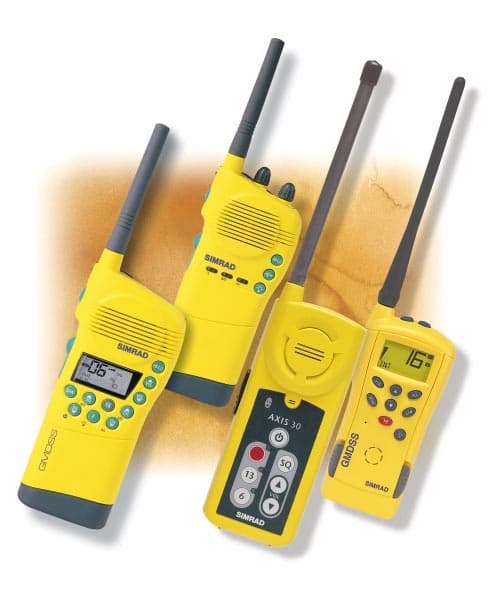
GL7AXIS50
Feb 16, 2000VHF handheld
Equipment Class
GHH - Part 80 VHF Hand Held Transmitter (GMDSS)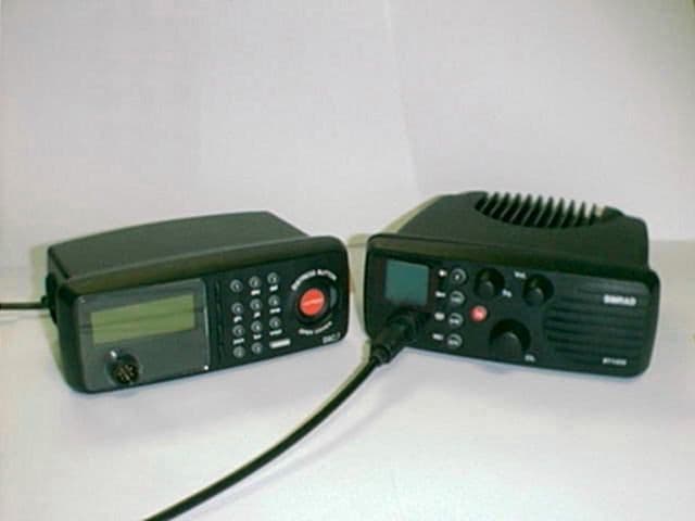
GL7DSC1400
Jul 15, 1999RT1400 + DSC1400
Equipment Class
TNB - Licensed Non-Broadcast Station Transmitter
GL7AXIS30
Nov 08, 1998GVH - Part 80 VHF Transmitter (GMDSS)
Equipment Class
GVH - Part 80 VHF Transmitter (GMDSS)