GL7RT63RT63 VHF marine Radiotelephone with DSC interface
Navico UK Ltd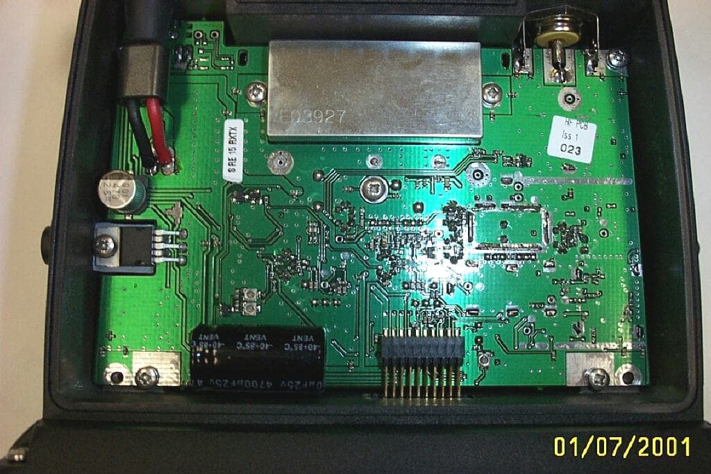
Click to zoom
Application Details
- Equipment Class
- TNB - Licensed Non-Broadcast Station Transmitter
- Date of Grant
- Jul 08, 2001
- Application Purpose
- Original Equipment
- Date of Application
- May 24, 2001
- Equipment Note
- RT63 VHF marine Radiotelephone with DSC interface
- Frequency Range
- 156.52500000 - 156.52500000
- Company
- Navico UK Ltd
- Country
- United Kingdom
Documents & Files
Document Text
Text extracted from the exhibit documents filed with the FCC. Open a document above to read the original.
Block Diagram
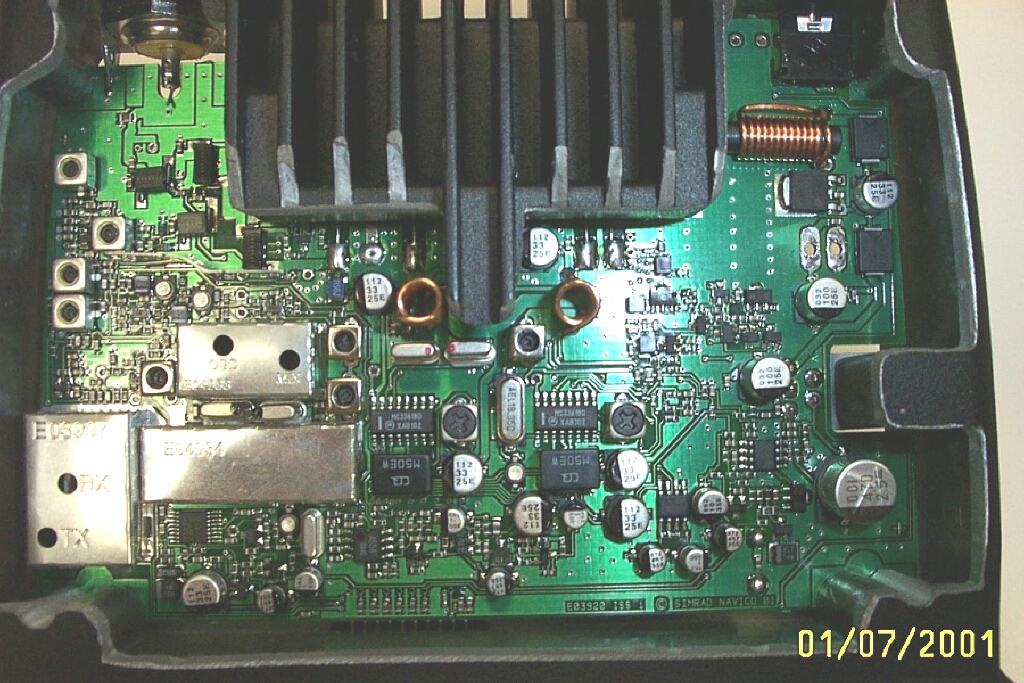
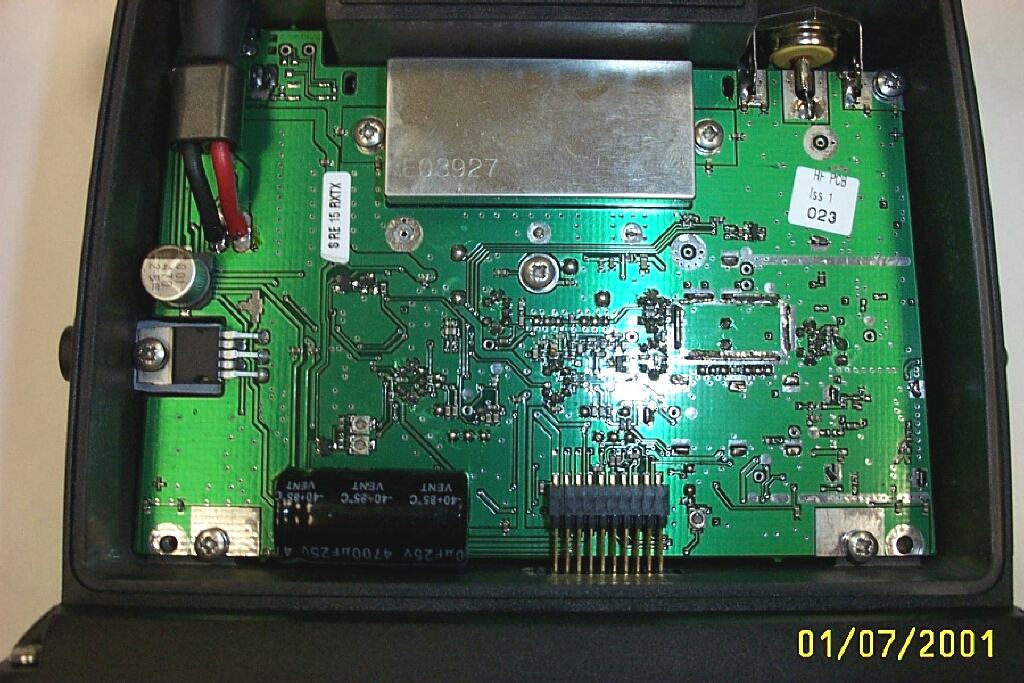
DRAFT DRAFT 1 CONTENTS Legend: TBC – To Be Confirmed (When pre-production modules are available / diagrams released for issue). NYC – Not Yet Completed – Awaiting Resources. 1 INTRODUCTION 1.1 Electronic PCBs 1.2 Mechanical Components 2 OPERATION 3 ASSEMBLY INSTRUCTIONS 3.1 RT62 / RT64 Chassis Pre-Assembly 3.2 RT62 / RT64 Front Panel Pre-Assembly 3.3 RT62 / RT64 Final Assembly 3.4 RD68 Chassis Pre-Assembly (TBC) 3.5 RD68 Front Panel Pre-Assembly (TBC) 3.6 RD68 Final Assembly TBC) 3.7 FTM5 Fist Mic Assembly (RD68 Only) 3.8 FTM6 Fist Mic Assembly (RT62 / RT64 Only) (NYC) 3.9 THS4 Telephone Handset Assembly (RD68 Only) 3.10 THS5 Telephone Handset Assembly (RT62 / RT64 Only) (NYC) 4 MECHANICAL ASSEMBLY DRAWINGS Not yet released for issue by R&D 5 CIRCUIT DESCRIPTIONS 5.1 Receiver / Transmitter PCB Assembly 5.2 Control PCB Assembly (RT62 / RT64 Only) 5.3 Control PCB Assembly (RD68 Only) (TBC) 6 CIRCUIT DIAGRAMS Not yet released for issue by R&D 7 PROGRAMMING AND CONFIGURATION Not yet produced 8 FAULT FINDING Not yet produced DRAFT DRAFT 2 9SPARE PARTS DETAIL Not yet produced 10TECHNICAL NOTES None Issued DRAFT DRAFT 3 1 INTRODUCTION TO THE AXIS FIXED VHF RADIO TELEPHONE The Axis fixed VHF range is robustly constructed using a pressure die cast aluminium case for effective heat dissipation ensuring maximum transmission performance even after many hours of constant use. The radio is designed to meet or exceed stringent International regulations including ETS300-162 and EN301-025. AXIS RT62 - Has full international channel capability; 16 pre-programmed private channels; features Dual and Tri Watch, Channel Inhibit and Revert, Scan and full memory operation; back-lit LCD display featuring large, 14 segment numerals to indicate working channel above smaller legends providing operational and status information; available with either fist-mic or telephone handset. AXIS RT63 - The RT63 is similar to the RT62 but includes features only required in the USA. Items referred to in the DSC receiver block diagram are omitted. DSC received audio is shared with the voice receiver. When the voice channel is inactive, the radio scans channel 70. DSC AF and AF pins of the handset connector are joined for this purpose. Note all references to the RT62 apply to this version. AXIS RT64 – Offers the same facilities as the RT62 Model with an additional watch-keeping receiver allowing it to use the Digital Selective Calling (DSC) system for routine and distress calling on VHF Channel 70. To access this feature the RT64 must be linked to a Simrad Class D DSC control unit DSC1400. AXIS RD68 – Offers the same facilities as the RT64 with a built in Class D DSC Controller to facilitate routine and distress calling on VHF Channel 70. Digitally Selected Calls are quicker and simpler to make than traditional voice calls using Channel 16 and should a distress situation occur, an alert can quickly be raised indicating identity, position and nature of the emergency and automatically establish communication on the emergency voice channel The main components of the Simrad Fixed VHF range are: 1.1 Electronics PCBs a.Receiver / Transmitter PCBDrawing No. E03921 b.Control PCBRT62 / RT64Drawing No. E03924 c.Control PCB RD68Drawing No. E03658 d.Fist Mic FTM5 (RD68) e.Fist Mic FTM6 (RT62/64)Drawing No. E03950 f.Telephone Handset THS4 f.Telephone Handset THS5Drawing No. E03953 1.2 Mechanical Components a.RT62 / RT64 ChassisDrawing No. E04086 b.RD68 ChassisDrawing No. E04093 DRAFT DRAFT 4 c.RT62 / RT64 Front PanelDrawing No. E04088 d.RD68 Front PanelDrawing No. E04099 f.FTM6 General AssemblyDrawing No. E04084 g.THS5 General AssemblyDrawing No. E03162 DRAFT DRAFT 5 2 OPERATING SIMRAD VHF RADIOs This Service Manual only contains operating instructions for those features of Simrad Radio that are not normally available to the end user. For details of normal operation please refer to the appropriate Simrad Instruction Manual. LCD Test Mode. The LCD test mode may be entered by holding Soft Keys 2 and 4 on power up. Depressing each key in turn will then fill the display with the appropriate characters. The radio must be turned off to exit test mode. DRAFT DRAFT 6 3 ASSEMBLY INSTRUCTIONS 3.1 RT62 / RT64 Chassis Pre-Assembly Refer to Chassis Assembly Drawing number E04086 and General Assembly Drawing numbers E04091 (RT62) and E04092 (RT64) Ensure that the “Coolpads” Part numbers E04067 and E04068 are fitted to the AF Amplifier and PA Module Platforms. Fit an appropriate PCB, E03921 for RT62 or E04089 for RT64, into the chassis carefully locating the extension loudspeaker socket, antenna connector and UHF Grounding Washer. Locate the 2 insulators E03998 one to each of the securing screw apertures at each side of the PA Module and fit the 6 screws 200294 as indicated. Ensure that the screw securing the AF Amplifier IC is fitted with an M3 Insulating Washer 200081. Solder the 2 cables from the power connector E03323 onto the PCB and withdraw any slack in the cables. Solder the tinned copper wire from the Antenna socket onto the antenna pad and angle the tags of the UHF Grounding Washer away from the antenna connector and solder each to the earth plane. Locate and fit the 3 PCB Compression Rubbers E03999 into the front of the casing. 3.2RT62 / RT64 Front Panel Pre-Assembly Refer to Front Panel PCB Assembly Drawing Number E04088. Ensure that the front case printing on the window and keypad is correct for the product under assembly and that the window and the LCD face are clean and free from dust. Offer the PCB, E03924, up to the case front ensuring that the shanks of the 3 rotary controls fit through the appropriate aperture and that the pins of the handset / fistmic socket engage through the PCB. Fit an “O” Ring, 190044, to each of the 3 Control Knobs, 2 x E03103:BK and 1 x E03102:BK. Apply a smear of Multi Purpose Grease PFG-210, Part Number 260002, to each of the “O” Rings and fit the knobs to the rotary controls pressing firmly home. Solder the fist…
Text truncated - open the document above for the full version.
Test Report
NAVIGATION AND COMMUNICATION SYSTEMS REPORT FORM FOR TESTING RT63 TO EN 301 025 RADIO EQUIPMENT AND SYSTEMS RADIOTELEPHONE TRANSMITTERS AND RECEIVERS FOR THE MARITIME MOBILE SERVICE OPERATING IN THE VHF BANDS TECHNICAL CHARACTERISTICS AND METHODS OF MEASUREMENT Test Report Number: TAR008 CONTENTS Page Section 1 Introduction.............................................................3 Section 2Product.....................................................................4 Section 3Test Schedule...........................................................4 Section 4Test Technical Details....................................................5 Section 5Summary of Tests.................................................................6 Section 6 General and operational requirements....................................... 8 Section 7 Technical Requirements.................................................. 11 Section 8 Enviromental Test Results....................................................14 Section 9Transmitter Test Results.......................................................18 Section 10 Receiver Test Results........................................................36 Section 11DSC 2nd Receiver Test Results....................................51 Section 12Test Equipment List..................................................60 Section 13Measurement Scan Results..............................................61 Section 14 Photographs of EUT............................................................65 Section 15Supplements...........................................................69 SECTION 1 INTRODUCTION This report contains the results of tests performed on the product RT63 VHF radio , on this premises of : Simrad Navico Ltd Star Lane Margate Kent CT9 4NP Simrad Navico Ltd complies with the accreditation criteria requirements of the quality standards, BS EN ISO 9001:1994. The accreditation covers the quality system of the EMC test department as well as the, design,manufacture, distribution, aftersales, marketing and support of communications and marine electronics for the leisure, commercial and military markets, as described in the certificate of approval bearing the certificate number 21460 and granted on 3 december 1998 for a period of 3 years. All testing was carried out within the EMC test department of Simrad Navico Ltd, to the requirements of ETSI EN 301 025 V1.1.1 (1998-08). Testing carried out by:Kevin Heath Report checked by:David Sheekey Date:9th April 2001 SECTION 2 PRODUCT A sample of the following product was submitted for testing: Maritime Integraded Radiotelephone and external DSC controller. Manufacture:Simrad Navico Ltd Parts of Product:1 x RT63; Transceiver Unit 1 x DSC1400 DSC Controller. 1 x Fistmike. Serial Number:TA Unit 1 Software Release:Issue 1 Particulars:DSC Class D in accordance with RTCM Standard SC101 SECTION 3 TEST SCHEDULE Tests were carried out in accordance with the specification detailed in clause 6 EN 301 025 document, "general conditions of measurement". All tests were carried out at Simrad Navico Ltd. The sample unit was tested between the following dates: 29th March 2001 - 6th April 2001. The RT63 VHF radio and DSC1400 DSC controller, is intended for use in the following application area: MARINE COMMUNICATIONS EQUIPMENT SECTION 4 TEST TECHNICAL DETAILS Test Unit = RT63 VHF Radio Serial Number = TA UNIT 1 Additional Parts =DSC1400; DSC Controller / Fistmike Nominal Voltage = 12.0 Volts Maximum Voltage = 15.6 Volts Minimum Voltage = 10.8 Volts Nominal Temperature = 20°C Maximum Temperature = 55°C Minimum Temperature = -15°C Channel 16 = 156.800MHz Upper Frequency = 163.000MHz Lower Frequency = 155.000MHz Second Receiver Frequency = 156.525MHz Channel Spacing = 25.0kHz First IF Main Rx = 21.4MHz Second IF Main Rx = 450.0kHz First IF 2nd Rx = 17.9MHz Second IF 2nd Rx = 450.0kHz Rated Audio Power = 2.0 Watts( external speaker ) 2 mW( handset earphone ) Rated Audio Load = 4 Ohms( external speaker ) 300 Ohms( handset earphone ) SECTION 5 SUMMARY OF TEST RESULTS Clause NoGeneral and operational requirementsR&TTEComplies? 4.1 General3.3e Yes 4.2 Composition3.3e Yes 4.3 Construction3.3e Yes 4.4 Controls and indicators3.3e Yes 4.5 Facilities for coding and decoding of DSC3.3e Yes 4.5.1 Call functions3.3e Yes 4.5.2 Manual calls3.3e Yes 4.5.3 Distress calls3.3e Yes 4.5.4 All ships calls3.3e Yes 4.5.5 Incoming calls3.3e Yes 4.6 DSC display3.3e Yes 4.7 Handset and loudspeaker3.3e Yes 4.8 Safety precautions 3.3e Yes 4.9 Labelling3.3e Yes 4.10 Warm up3.3e Yes Technical Requirements 5.1 Switching time3.3e Yes 5.2 Class of emission and modulation characteristics3.3e Yes 5.3 Facilities for DSC transmission and reception3.3e Yes 5.3.1 General3.3e Yes 5.3.2 Decoding3.3e Yes 5.3.3 Free channel transmission3.3e Yes 5.3.4 Automatic acknowledgement3.3e Yes 5.3.5 Automatic re-transmission of distress calls3.3e Yes 5.4 Ships identity - MMSI and group MMSI3.3e Yes 5.5 Entry of position information3.3e Yes 5.6 Alarm circuits3.3e Yes 5.6.1 Distress and urgency 3.3e Yes 5.6.2 Other categories3.3e Yes 5.6.3 Acoustic alarms3.3e Yes 5.6.4 Cancellation of alarms3.3e Yes 5.7 Facilities for automatic identification N/a 5.8 Multiple watch facilities 3.3e Yes 5.8.1 General3.3e Yes 5.8.2 Scanning provisions3.3e Yes 5.8.3 Scanning characteristics3.3e Yes Enviromental Tests 7.4 Vibration3.3e Yes 7.5 Temperature Tests3.3e Yes 7.5.2 Dry heat3.3e Yes 7.5.3Damp Heat3.3eYes 7.5.4Low temperature3.3eYes 5 SUMMARY OF TEST RESULTS (continued) Clause No.TransmitterR&TTEComplies? 8.1 Transmitter Frequency Error 3.2 Yes 8.2 Transmitter Carrier Power 3.2 Yes 8.3 Transmitter Frequency Deviation 3.2 Yes 8.3.3 Reduction of frequency deviation at mod freq above 3 kHz3.2 Yes 8.4 Sensitivity of Modulator Including Microphone3.3e Yes 8.5 Transmitter Audio Frequency Response3.3e Yes 8.6 Transmitter Audio Frequency Distortion 3.3e Yes 8.7 Transmitter Adjacent Channel Power 3.2 Yes 8.8 Transmitter Conducted Spurious Emiss…
Text truncated - open the document above for the full version.
Test Report
NAVIGATION AND COMMUNICATION SYSTEMS REPORT FORM FOR TESTING TO EN 300 828 Test Report Number: EMC037 ELECTROMAGNETIC COMPATIBILITY AND RADIO SPECTRUM MATTERS (ERM) ELECTROMAGNETIC COMPATIBILITY (EMC) FOR RADIOTELEPHONE TRANSMITTERS AND RECEIVERS FOR THE MARITIME MOBILE SERVICE OPERATING IN THE VHF BANDS Simrad Navico Ltd Test Report to EN 300-828 CONTENTS Page Section 1 Introduction.....................................................................3 Section 2Product...........................................................................4 Section 3Test Schedule.................................................................4 Section 4Test Technical Details.......................................................5 Section 5 Summary of Tests............................................................6 Section 6 Results........................................................................... 7 Section 7 Test Equipment List........................................................13 Section 8Measurement Scan Results...............................................14 Section 9Photographs of EUT..........................................................20 Page 2Test Report Number: EMC037 Simrad Navico Ltd Test Report to EN 300-828 SECTION 1 INTRODUCTION This report contains the results of tests performed on the product RT63 VHF radio with ATIS, on this premises of : Simrad Navico Ltd Star Lane Margate Kent CT9 4NP Simrad Navico Ltd complies with the accreditation criteria requirements of the quality standards, BS EN ISO 9001:1994. The accreditation covers the quality system of the EMC test department as well as the, design,manufacture, distribution, aftersales, marketing and support of communications and marine electronics for the leisure, commercial and military markets, as described in the certificate of approval bearing the certificate number 21460 and was granted on 3 december 1998 for a period of 3 years. All testing was carried out within the EMC test department of Simrad Navico Ltd, to the requirements of EN 300 828 V1.1.1 (1998-03). Testing carried out by:.............................................. Report checked by:.............................................. Date:...................... Page 3Test Report Number: EMC037 Simrad Navico Ltd Test Report to EN 300-828 SECTION 2 PRODUCT A sample of the following product was submitted for testing: Maritime VHF Radiotelephone with ATIS Manufacture:Simrad Navico Ltd Parts of Product:RT63; Transceiver Unit with ATIS. Handset or Fistmike. Serial Number:TA Unit 1 Software Release:Issue 1 Particulars:None SECTION 3 TEST SCHEDULE All tests were carried out within the EMC department at Simrad Navico Ltd. The sample unit was tested between the following dates: 1st March 2000 - 14th April 2000. The RT63 VHF radio with ATIS, is intended for use in the following application area: MARINE COMMUNICATIONS EQUIPMENT; and was tested to ETSI EN 300 828 V1.1.1(1997-12). The following tests shown below were carried out on a sample of the RT63 VHF radio with ATIS Test ClauseDescription of TestDate of Test 8.1.2.1Radiated Emissions (150kHz-30Mhz) 8.2DC Power Ports 9.1RF Electromagnetic Field (80Mhz-1Ghz) 9.2Electrostatic Discharge 9.4Conducted disturbances induced by RF fields (150Khz-80Mhz) 9.6Power Supply Failure Excempt from Testing Test ClauseDescription of TestReason This test is covered and exceeded by EN 300-162 (March 1998), See RT63 VHF radio test report TAR003, for test results. This test was not conducted as no cables were longer than 3 metres. This test is required on AC power input ports only, the RT63 requires a 12v DC input only, therefore is excempt. This test is required on AC power input ports only, the RT63 requires a 12v DC input only, therefore is excempt. Radiated Emissions (30Mhz-1Ghz) Fast Transient Power Supply Short Term Vari Surge 8.1.2.2 9.3 9.5 9.7 Page 4Test Report Number: EMC037 Simrad Navico Ltd Test Report to EN 300-828 SECTION 4 TEST TECHNICAL DETAILS Test Unit = RT63 VHF Radio with ATIS. Serial Number = TA UNIT 1 Additional Parts = Telephone handset / Fistmike Nominal Voltage = 12.0 Volts Nominal Temperature = 20°C Channel 16 = 156.800MHz Upper Frequency = 162.975MHz Lower Frequency = 155.025MHz Second Receiver Frequency = 156.525MHz Channel Spacing = 25.0kHz First IF Main Rx = 21.4MHz Second IF Main Rx = 455.0kHz First IF 2nd Rx = 17.9MHz Second IF 2nd Rx = 455.0kHz Rated Audio Power = 6.0 Watts( external speaker ) 2 mW( handset earphone ) Rated Audio Load = 4 Ohms( external speaker ) 300 Ohms( handset earphone ) Page 5Test Report Number: EMC037 Simrad Navico Ltd Test Report to EN 300-828 SECTION 5 SUMMARY OF TEST RESULTS Clause NoDescription of TestComplies? 8.1.2.1 Radiated Emissions (150kHz-30Mhz)Yes 8.1.2.1 Radiated Emissions (30Mhz-1Ghz)Yes* 8.2 DC power in/outYes 9.1 RF electromagnetic field (80Mhz-1Ghz)Yes 9.2 Electrostatic DischargeYes 9.3 Fast TransientsYes* 9.4 Conducted disturbances induced by RF fields (150Khz-80Mhz)Yes 9.5 Power Supply Short Term VariationsYes* 9.6 Power Supply FailureYes 9.7 SurgeYes* Note: * = See Section 3 (excempt from testing) The test sample of RT63 VHF radio with ATIS has successfully passed a series of tests to EN 300 828 V1.1.1(1998-03), which indicate its compliance with the EMC criteria of ETSI EN 300 828 V1.1.1 (1998-03). Page 6Test Report Number: EMC037 Simrad Navico Ltd Test Report to EN 300-828 SECTION 6 RADIATED EMISSIONSClause :8.1 Definition:This test assesses the ability of the EUT to limit unwanted emissions from the enclosure. Product:RT63 VHF Radio with ATIS. Method:As per EN 300-828, clause 8.1.2.1. Results: General conditions: Date of test:27th March 2000 Temperature:Tnom (20°C) Relative Humidity:32% Rated power: 25 Watts Supply:Vnom (12V) Channel tested:156.800MHz To identify any potential emissions the EUT was placed inside a anechoic chamber, connected to 12v dc power supply. With the radio placed in receive and (25w) transmit mode, a measurement scan was then carried…
Text truncated - open the document above for the full version.
Test Report
U:\NAVICO\GLOBAL\APPROVAL\USA\Rt63 Uploads\Occupied Bandwidth.doc Test Report: RT63 Occupied bandwidth Additional testing was carried out on a sample RT63 to CFR47 part 2 paragraph. (2.1049(occupied Bandwidth) Method The sample radio was connected to an AF source and modulation meter. The AF frequency was set to 2500Hz and the level set to 2.5kHz deviation. (50% maximum allowable deviation. The level was increased 16dB and the AF frequency swept to find the maximum deviation. The spectrum was then plotted on a spectrum analyser and the results plotted. Test Equipment AF sourceRohde & Schwarz CMTA Modulation MeterAs Above Spectrum AnalyserRohde & Schwarz FSEA Results The Occupied bandwidth meets the requirements of Part 80.211(f) Occupied Bandwidth -60 -50 -40 -30 -20 -10 0 10 20 30 40 156.7156.72156.74156.76156.78156.8156.82156.84156.86156.88156.9 MHz dBm
Contact Information
Applicant
David C. Sheekey(Product Expert)
Technical Contact
Simrad Navico LtdDavid Sheekey
[email protected]44 1843 290290
Star Lane · Margate, Kent · United Kingdom
Technical Specifications
| # | Rule Parts | Frequency Range | Power Output | Emission | Tolerance |
|---|---|---|---|---|---|
| 3 | 8 | 156.525 MHz - 156.525 MHz | 25 W | 14K0G2B | 10 ppm |
Other Applications from Navico UK Ltd
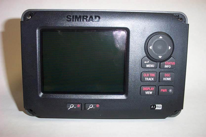
GL7AI50
Oct 02, 2008Class B AIS transponder
Equipment Class
AIS - Automatic Identification SystemsGL7RD68
Dec 18, 2000VHF Marine radiotelephone inc class 'D' DSC controller
Equipment Class
TNB - Licensed Non-Broadcast Station Transmitter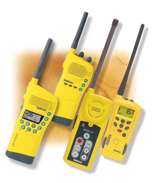
GL7AXIS50
Feb 16, 2000VHF handheld
Equipment Class
GHH - Part 80 VHF Hand Held Transmitter (GMDSS)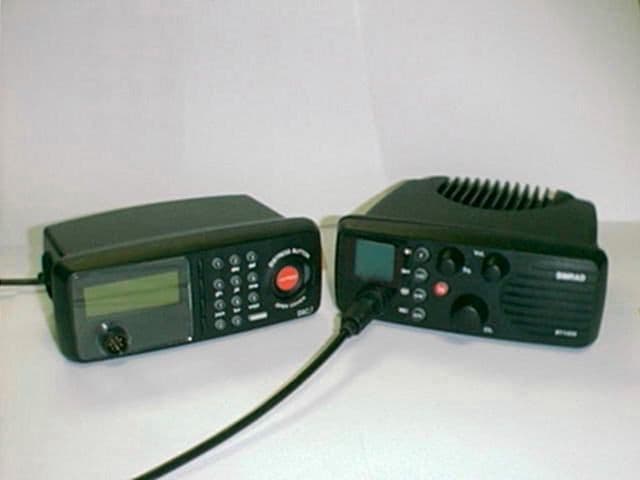
GL7DSC1400
Jul 15, 1999RT1400 + DSC1400
Equipment Class
TNB - Licensed Non-Broadcast Station Transmitter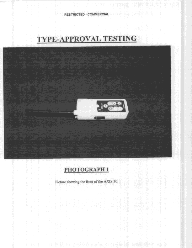
GL7AXIS30
Nov 08, 1998GVH - Part 80 VHF Transmitter (GMDSS)
Equipment Class
GVH - Part 80 VHF Transmitter (GMDSS)