GL7AXIS50VHF handheld
Navico UK Ltd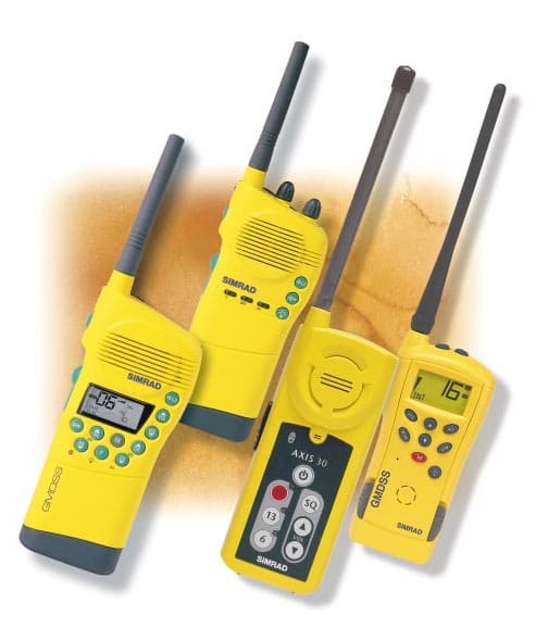
Click to zoom
Application Details
- Equipment Class
- GHH - Part 80 VHF Hand Held Transmitter (GMDSS)
- Date of Grant
- Feb 16, 2000
- Application Purpose
- Original Equipment
- Date of Application
- Dec 07, 1999
- Equipment Note
- VHF handheld
- Frequency Range
- 155.00000000 - 163.00000000
- Company
- Navico UK Ltd
- Country
- United Kingdom
Documents & Files
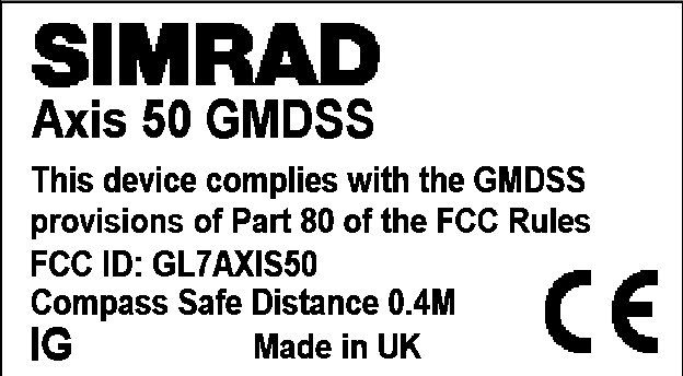
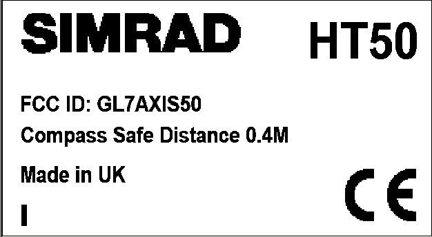
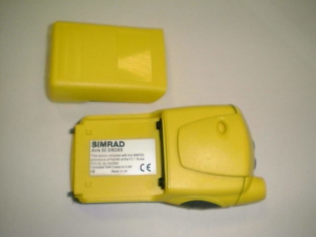
Document Text
Text extracted from the exhibit documents filed with the FCC. Open a document above to read the original.
External Photos
SIMRAD MARKETING 3.000 10.99 WORLDWIDE MANUFACTURER OF MARINE ELECTRONICS Technical Specifications Manufacturer: Simrad Navico Ltd. Star Lane, Margate Kent, CT9 4NP, UK Telephone: + 44 (0)1843 290 290 Telefax: + 44 (0) 1843 290 471 off on Battery Charger CRC status rear charge charge AXIS 150/250AXIS 50 AXIS 30 79mm (3.1in) 69mm (2.7in)42mm (1.65in) 177mm (6.97in) 308.5mm (12.15in) 69mm (2.7in) 60mm (2.35in) 42mm (1.65in) 25.5mm (1in) 46mm (1.8in) 90mm (3.55in) 98mm (3.58in) 177mm (6.97in) 85mm (3.35in) 308.5mm (12.15in) 79mm (3.1in) 68mm (2.7 in) 42mm (1.7 in) 320mm (12.8 in) 145mm (5.8 in) AXIS 30 72mm (2.88in) 57mm (2.28in) 172mm (6.88in) 345mm (13.8in) *Contact your local sales office for regional variations of these mains adaptors. Note: Specifications are subject to change without notice. www.simrad.com ETS300-225 plus IMO, ITU, SOLAS, and FCC CFR47 part 80 GMDSS rules GMDSS models TYPE APPROVAL ETS300-255 plus IMO, ITU, SOLAS and FCC CFR47 part 80 GMDSS rules ETS300-255 plus IMO, ITU, SOLAS and FCC CFR47 part 80 GMDSS rules 0.6 kg (1.32 lbs)Weight GENERAL 0.4 kg (0.88 lbs)0.4 kg (0.88 lbs) 4 Watts/1Watt switchableOutput Power TRANSMIT 0.5 watts ERP2.5Watts 1Watt switchable 1Watt maxAudio Output Power RECEIVE ACCESSORIES 0.4 watts0.4 watts 125mA (typ)Power Consumption150mA at 0.4W 10mA squelched 0.2A (typ) <0.5μV for 20dB SINADSensitivity<0.5μV for 20dB SINAD<0.5μV for 20dB SINAD 75dBRejection of Unwanted Signals70dB70dB <1nWSpurious Emissions<2nW<2nW NCB700700mAH NiCdNot Available NCB850850mAh NiCdNot AvailableNC08 LTB1:YLithium BatteryLTB2:YLTB3:Y Not AvailableTest battery (non rechargeable)TSTB1Not Available TCH12 CTC1 (Mains Voltage Supply) Trickle ChargerNot AvailableTC50 CRC1 (Mains Voltage Supply)Rapid ChargerNot AvailableRC50 MAD230Mains Adaptor for Trickle Charger* Not AvailableMAT50 RAD230Mains Adaptor for Rapid Charger* Not AvailableMAR50 WPSM1:YWaterproof Speaker MikeNot AvailableNot Available LYD1LanyardNot AvailableLYD1 LC1Leather Carrying CaseNot Available SS1Shoulder StrapNot Available FLT1Flotation CollarNot Available HS1Hand StrapNot AvailableNot Available 1.4A at 4W, 0.8A at 1WPower Consumption0.35A0.95A at 2.5W, 0.6A at 1W. -20 O to +60 O CTemperature Tolerance-20 O to +55 O C-20 O to +55 O C 25KHz (12.5KHz on request)Channel Spacing25KHz25KHz 700mAh NiCd rechargeable 850mAh NiCd rechargeable Lithium primary battery Battery OptionsLithium primary battery (non rechargeable test battery) Lithium primary battery 155-163MHzFrequency RangeCh06, Ch13 and Ch16 only155-163MHz 80mm (3.2 in) 70mm (2.8 in) 96mm (3.8 in) WORLDWIDE MANUFACTURER OF MARINE ELECTRONICS VHF RADIOTELEPHONE Navico AXIS Series GMDSS VHF Handheld radios for everyday and survival craft use Since they were first launched, AXIS radios have become internationally recognised as outstanding examples of design and performance in handheld VHF. It is because of such high standards that AXIShas found favour with some of the most demanding users in the world, including the British Royal Navy, the French Navy, the RNLI and the US Navy Seals as well as major shipping companies worldwide. With modern, high-impact materials, the latest micro electronics, and designs that are thoroughly practical in every detail, the AXIS range are the toughest, most efficient and most user friendly handheld VHF radios on the market. Simrad has the widest range of GMDSS handhelds to suit every need. The basic AXIS 30 is for GMDSS emergency use only, the AXIS 50 GMDSS provides a cost effective handheld for safety and on board use, while the AXIS 150 and 250 GMDSS models meet the requirements of the most demanding users. Waterproof All models are fully sealed, and water- proof to a depth of 1 meter, with 45°C thermal shock. Impact resistant Careful choice of case materials, the internal construction and a flexible antenna, means any AXIS handheld will withstand being dropped from a height of 1 meter onto a hard surface. High performance With their advanced electronic circuitry, all models surpass global requirements for receiver sensitivity and sustained power output. AXIS 150/250 GMDSS When fitted with rechargeable batteries, the AXIS 150 and 250 GMDSS serve as excellent handheld radios for on board use, as well as meeting all the requirements for emergency use with the lithium battery pack. The AXIS 250 provides all the required channels and has push button controls of all functions, making it easy to use with a gloved hand in all weather conditions. The AXIS 150 has 16 channels with rotary control for primary functions. AXIS 30 – floats in sea water Recharging Unit A reputation that speaks volumes Both models feature illuminated channel indicators to enable effective use in total darkness. AXIS 30 The AXIS 30 is purpose designed as a GMDSS compliant handheld for survival craft use. Large, clear controls ensure easy operation by untrained personnel. AXIS 50 GMDSS As the latest addition to the range, the AXIS 50 provides a competitive solution for both on board and emergency use. Although smaller than its predecessor, the AXIS 50 provides a similar level of performance. Its high efficiency antenna gives the best possible range, whilst maximising battery life. All the features expected on a modern handheld are provided. The clear LCD shows channel, operating and battery status, and can be illuminated for night time use. AXIS 250AXIS 150AXIS 50AXIS 30 CHANNEL CAPACITY DUAL WATCH TRI WATCH MEMORY SCAN MEMORY MODE PUSH BUTTON OPERATION ROTARY CONTROLS CLEAR LCD DISPLAY LED INDICATORS ILLUMINATED DISPLAY ACCESSORY SOCKET BATTERY OPTIONS POWERSAVE MODE FEATURES Lithium 700 and 850mAh NiCd rechargeable and lithium 700 and 850mAh NiCd rechargeable and lithium 850 mAh NiCd rechargeable –√√√ –√√– –√Channel indicator√ Channel, transmit status– Receive, transmit and battery status – – Shows channel, signal, battery strength and operating status – Shows channel, battery condition and operating status –– Channel select, volume and squelch All fun…
Text truncated - open the document above for the full version.
External Photos
80mm (3.2 in) 70mm (2.8 in) 96mm (3.8 in) 68mm (2.7 in) 145mm (5.8 in) 42mm (1.7 in) 320mm (12.8 in) SIMRAD MARKETING 2.000 03.98 WORLDWIDE MANUFACTURER OF MARINE ELECTRONICS Technical Specifications VHF: Power Supply: 700mAh NiCd rechargeable battery 1200mAh NimH rechargeable battery (Optional) Power Drain: Rx 0.2 Amps,Tx (5W) 1.5 Amps (typical) Modes: Simplex / Semi-Duplex Channels: All international / USA (inc.Wx) plus special regional channels as allowed Type Approval: EN301-178 Transmitter Power Output: High 5W / Low 1W max Spurious emissions: <-70dBc Deviation: ±5kHz max Receiver Sensitivity: <1mV EMF / 20dB SINAD AF output: 400mW @ 10% dist Adjacent Channel Selectivity: >70dB Inter-modulation Rejection: >70dB Hum and Noise: <-40dB Construction High impact resistance plastic case Aluminum die-cast chassis Dimensions / Weight 145mm x 68mm x 42mm (without antenna) 0.4kg Environmental: -20 to +55 O C 95% rel. hum. @ 40 O C Drop resistance: 1 meter onto hard wood surface Water Resistance 1meter submersion for 1Hour EMC: EN60945 Optional Accessories Batteries: NC70700mAh Nickel Cadmium rechargeable battery pack NH121200maH Nickel metal hydride rechargeable battery pack Chargers: TC50Trickle charger (approx 14 hour, 12Volt) RC50Rapid charger (approx 1 hour, 12Volt) MAT50Mains adapter for trickle charger MAR50 Mains adapter for rapid charger Accessories: LYD1Lanyard Manufacturer: Please email the correct adress to me. Note: Specifications are subject to change without notice. www.simrad.com HANDHELD VHF R/T Simrad HT50 WORLDWIDE MANUFACTURER OF MARINE ELECTRONICS Perfectly adapted to life at sea Easy to operate If you have ever struggled with the fiddly little buttons of some handheld VHF radios, the control of the HT50 will come as a reve- lation. Even in the bitter cold with gloved hands, you can easily press the buttons you want without inadver- tently pressing any- thing else. Operation is simple, logical and intuitive, with clear LCD screen graphics to indicate the selected channel and operating mode. As tough as they come Designed in accordance with the GMDSS maritime safety regulations, the HT50 will withstand being dropped from a height of 1 metre onto a hard surface. The rubber encased flexible aerial is stud mounted for maximum durability, and all the controls are push-button keys, so there are no projections that might be vulnerable to knocks. Watertight to 1 meter The GMDSS rules also require handheld VHF radios to be sufficiently waterproof to cope with use in a liferaft. The casing and controls of the HT50 are fully sealed, to make the radio not just weatherproof, but sufficiently watertight that it can be immersed to 1 meter without coming to any harm. Dependable performance. Thanks to its superbly designed electronics, the HT50’s reception clarity, transmitter efficiency and resis- tance to interference are more than a match for any of its competitors. In addition to the maximum 5 Watt transmission power, for short distance calls in harbours and marinas, there is a low power 1 Watt setting to preserve battery life. Included as standard are a standard 700mAh rechargeable battery and 12V DC charger. An optional high capacity 1200mAh nickel metal hydride battery pack and rapid charger are also available if required. Custom channel choice. The HT50 features 54 international channels, plus up to 16 additional channels used for particular country requirements and for commercial users. With dual- and tri-watch, as well as all channel scan and memory scan (where permit- ted), it has a power- ful ability to monitor the airwaves. Simrad HT50 VHF The definitive handheld VHF Radiotelephone. The HT50’s predecessors earned quite a reputation for their robust construction and dependable reliability, making them highly prized by coastguards, rescue services and defence forces around the world. Designed and built to the same high standards – but smaller, more economical and even easier to handle – the new HT50 is indeed a worthy successor. Even in the bitter cold with gloved hands,you can easily press the buttons you want without inadvertently pressing anything else The HT50 is supplied with rechargeable nicad battery in a fully sealed housing and comes with a state of the art commercial charger Simrad electronics are constructed to be robust and withstand attacks from frost,rain,spray and ultra violet rays. CLEARLCDDISPLAY When turned on,channel 16 will automatically be selected In addition to showing the channel in use,battery condition and operation status is displayed All channel scan will automatically search for incoming signals Memory Scan for easy monitoring of commonly used channels Backlit LCD display gives easy readability in all conditions Easy to use control pad with dedicated push buttons High sensitivity microphone Distinct and clear loudspeaker Easy to clip on battery pack The high efficiency antenna is optimized for maximum performance Power switch for high and low transmit power selection Operation is simple, logical and intuitive, with clear LCD screen graphics to indicate the selected channel and operating mode. The tiny handheld VHF with big features •54 International Channelsplus special national channels •Dual Watchon Ch16 and current working channel •Tri-Watchincluding user selected working channel •Memory Scanscans commonly used channels •All Channel Scanautomatically searches for all incoming signals •Full Keypad Operationof all functions including volume and squelch •Powersaveautomatically switches to standby when no signal is being received •Rechargeable700mAh Nicad Battery with 1200mAh NimH option •Battery Chargerfor on board charging The HT50 is shown actual size
Schematics
DRAFT DRAFT 1 CONTENTS 1 INTRODUCTION 1.1 Electronic PCBs 1.2 Mechanical Components 2 OPERATION 3 ASSEMBLY INSTRUCTIONS 3.1Not yet available 4 MECHANICAL ASSEMBLY DRAWINGS 4.1 Not yet available 5 CIRCUIT DESCRIPTIONS 5.1RF PCB Assembly 5.2Control PCB Assembly 6 CIRCUIT DIAGRAMS 6.1 Circuit Schematics 6.2 Component Lists and Layouts 7 PROGRAMMING AND CONFIGURATION 7.1 Channel Characteristic Programming 7.2 Using the Programming Software 8 FAULT FINDING 8.1 Common User Faults 8.2 Common Technical Faults 9SPARE PARTS DETAIL 9.1 Spares 9.2 Service Aids 10TECHNICAL NOTES DRAFT DRAFT 2 1 INTRODUCTION TO THE HT50 VHF HANDHELD RADIO TELEPHONE The HT50 transceiver offers high performance, low power consumption, robust construction and dependable reliability in a small and easy to handle package. The shockproof casing with push button keys, for ease of operation, is fully waterproofed to a depth of 1 metre and will withstand the shock of being dropped onto a hard surface from a height of 1 metre. The HT50 embraces the following features: • 54 International Channels – plus special national channels • Dual Watch – on Channel 16 and current working channel • Tri-Watch – including user selected working channel • Memory Scan – scans commonly used channels • All Channel Scan – automatically searches for all incoming signals • Full Keypad Operation – of all functions including volume and squelch • Powersave – automatically switches to standby when no signal is being received • Rechargeable – 700mAh Nicad Battery with 1200 mAh NimH option • Battery Charger – for on board charging The main components of the HT50 are: 1.1 Electronics PCBs a.Radio Frequency PCB b.Control PCB 1.2 Mechanical Components Not yet available DRAFT DRAFT 3 2 OPERATING THE HT50 VHF HANDHELD RT 2.1This Service Manual only contains operating instructions for those features of the HT50 that are not normally available to the end user. For details of normal operation please refer to the HT50 Operation Manual, E0XXXX. 2.2 Power ON Combination Functions. There are several functions available which can only be accessed by pressing and holding down certain key combinations and switching the radio on. These functions and their method of activation are described below. Second Mode. Second Mode (alternative country) – hold down Volume key and press On. First Key Beep. When a key is first pressed a beep can be generated. This function can be toggled on and off by holding down the Squelch key and pressing the On button. NB. This function can be disabled by reprogramming the NVM, Section 7 refers. Programme Mode. The radio is placed in Programme Mode for programming and reconfiguration utilising a programming kit and a PC. Hold down SCAN, UP and DW keys and press On. NB. This mode can only be exited by switching the radio off and whilst in programming mode the radio will not transmit or receive. LCD Test Mode. Tests all legends – hold down Volume, Squelch, 16 and Lights keys and switch On. As each key is operated the appropriate legend appears. The radio will not transmit or receive in this mode and must be switched off to exit the mode. ATIS / DSC Test Mode (only available on special radios). Tone test mode is activated by holding down the Volume and Scan keys and switching on. Whilst in this mode the radio receives and transmits on channel 16. Tests are initiated by pressing keys as follows: SCAN Radio transmits a continuous ‘0’ tone (2100Hz) Display shows ‘00’ D/W Radio transmits a continuous ‘1’ tone (1300Hz) Display shows ‘11’ LITES Radio transmits alternating ‘010101’ tones Display shows ‘10’ 16 Radio receives on channel 16 Display shows ‘16’ Battery Cycle Test Mode (only available on special radios). The radio can be placed in this mode by holding down the UP & DOWN keys. While in this mode the radio operates on channel 16 and performs as follows • 6 seconds receive at full volume unmuted DRAFT DRAFT 4 • 48 seconds receive with audio muted • 6 seconds transmit at high power Exit from this mode can only be achieved by turning the radio off. Tx / Rx Cycle Test Mode (only available on special radios) The radio can be placed in this mode by holding down the SQUELCH & D/W keys. While in this mode the radio operates on channel 16 and performs as follows • 5 minutes receive at full volume unmuted • 5 minutes transmit at high power Exit from this mode can only be achieved by turning the radio off. DRAFT DRAFT 5 3 ASSEMBLY INSTRUCTIONS Not yet available DRAFT DRAFT 6 4 MECHANICAL ASSEMBLY DRAWINGS 4.1Not yet available DRAFT DRAFT 7 5 CIRCUIT DESCRIPTIONS Introduction The HT50 consists of 2 PCB assemblies. The RF PCB assembly, Navico Part No. E03466, contains all the transmitter and receiver circuitry including the synthesiser and Voltage Controlled Oscillator (VCO). The control PCB assembly, Navico Part No. E03463, houses the microprocessor, user controls, audio and supply regulation circuitry and the LCD drivers. The RF and Control PCBs are interconnected via a 20 way multi-connector. 5.1 Radio Frequency PCB. Refer to Drawing No. E03464. VCO and Frequency Synthesis. A crystal controlled oscillator operating at 21.85 MHz comprising transistor TR10, Crystal Xtal 3 and associated components provides the reference frequency for the synthesiser and acts as the second Local Oscillator in the receiver. The synthesiser IC3 is loaded with data from the Control PCB to select the frequency divide ratios appropriate to the channel selected. The Voltage Controlled Oscillator (VCO) is tuned by applying the output of the synthesiser to varactor diode CV2 via the filter C69, R43 and C71. The VCO operates at the fundamental frequency in transmit mode and at 21.4MHz below the receive frequency in receive mode. Modulation is achieved by applying the modulating signal, provided from the Control Board, IC7, to Varactor Diode CV1 and hence to the VCO. The VCO output is fed to buffer amplifiers TR4 and TR5 via R24 and C47and the output of the buffer is tuned by L11 and L1…
Text truncated - open the document above for the full version.
Test Report
Simrad-Navico Ltd.Axis50.xls09/12/99 Simrad logo here! REPORT FORM FOR TESTING TO ETS 300 225 RADIO EQUIPMENT AND SYSTEMS (RES) Technical Characteristics and methods of measurement for survival craft portable VHF radiotelephone apparatus Page 1 of 31 Navico Ltd.Axis50.xls09/12/99 Test Unit = Serial Number = Nominal Voltage = 7.2 Volts Maximum Voltage = 10.7 Volts Minimum Voltage = 6.0 Volts Nominal Temperature = 20°C Maximum Temperature = 55°C Minimum Temperature = -20°C Channel 16 = 156.800MHz Upper Frequency = 163.025MHz Lower Frequency = 155.025MHz Rated Output Power (RF) = 2.5 Watts Channel Spacing = 25.0kHz First IF Main Rx = 21.4MHz Second IF Main Rx = 450.0kHz Rated Audio Power = .4 Watts Rated Audio Load = 24 Ohms The data in this report was obtained from report number 98520930 dated 10th September 1999. This report was prepared by :- KTL Arnhem Utrechtweg 310 6800 JA Arnhem The Netherlands Page 2 of 31 Navico Ltd.Axis50.xls09/12/99 SUMMARY OF TEST RESULTS Serial No. 09/12/99 Clause No.DescriptionComplies? Notes. 8.1Transmitter Effective Radiated PowerYes 8.2Transmitter Radiated Spurious EmissionsYes All other emissions below the measurable limit. 8.3Receiver Spurious EmissionsYes All other emissions below maesurable limit. 9.1Transmitter Frequency ErrorYes 9.2Transmitter Output Power referred to ERPYes 9.3Transmitter Frequency DeviationYes 9.4Limiting Characteristic of ModulatorYes 9.5Sensitivity of Modulator Including MicrophoneYes 9.6Transmitter Audio Frequency ResponseYes 9.7Transmitter Audio Frequency DistortionYes 9.8Transmitter Adjacent Channel PowerYes 9.9Transmitter Residual ModulationYes 9.10Transmitter Transient Frequency BehaviourYes Values shown not exceeded during defined period 10.1Receiver AF Harmonic DistortionYes 10.1Receiver AF Output PowerYes 10.2Receiver Audio Frequency ResponseYes 10.3Receiver Maximum Usable SensitivityYes 10.4Receiver Co-Channel RejectionYes 10.5Receiver Adjacent Channel SelectivityYes 10.6Receiver Spurious Response RejectionYes All other responses greater than 90dB 10.7Receiver Intermodulation ResponseYes 10.8Receiver Blocking ResponseYes 10.9Receiver Amplitude Response of the LimiterYes 10.10Receiver Hum And NoiseYes Page 3 of 31 Navico Ltd.Axis50.xls09/12/99 Ambient Temperature = 25°C TRANSMITTER EFFECTIVE RADIATED POWER Clause:-8.1 Supply Voltage = 7.2 Volts Upper Limit = 25.0 Watts Lower Limit ( Normal ) = 0.25 Watts TEST CONDITIONSOUTPUT POWER (Watts) Pass/Fail 155.025MHz156.850MHz163.025MHz Tnom (20°C) Vnom (7V) 1.5Pass REFERENCE GAIN 1.01.0#DIV/0! Complies:- Yes Page 4 of 31 Navico Ltd.Axis50.xls09/12/99 Ambient Temperature = 20°C TRANSMITTER RADIATED SPURIOUS EMISSIONS 8.2 Supply Voltage = 7.2 Volts Output Power = 2.5 WattsLimit = 0.25uW Frequency of Spurious Emissions Spurious Emission Level (uW)Pass / Fail (MHz)155.025MHz156.900MHz163.025MHz 313.800 470.7000.0150Pass 627.600 784.500 941.4000.0500Pass 1098.300 1255.200 Notes: All other emissions below the measurable limit. Complies:- Yes Page 5 of 31 Navico Ltd.Axis50.xls09/12/99 Ambient Temperature = 20°C RECEIVER RADIATED SPURIOUS EMISSIONS Supply Voltage = 7.2 VoltsLimit = 2.0nW Frequency of Spurious Emissions Spurious Emission Level (nW)Pass / Fail (MHz)155.025MHz156.800MHz163.025MHz 135.400MHz0.050Pass 270.800MHz 406.200MHz 541.600MHz 677.000MHz 812.400MHz 947.800MHz 1083.200MHz Notes: All other emissions below maesurable limit. Complies:- Yes Page 6 of 31 Navico Ltd.Axis50.xls09/12/99 Ambient Temperature = TRANSMITTER FREQUENCY ERROR Clause:-9.1 Supply Voltage = 7.2 Volts High Power =2.5WLimit = 1.5kHz TEST CONDITIONSFREQUENCY ERROR (Hz) 155.025MHz156.800MHz163.025MHz Tnom (20°C) Vnom (7V) -147-174 Tmax (55°C) Vmin (6.0V) 388 Vmax(10.7V) 192 Tmin (-20°C) Vmin (6.0V) -728 Vmax(10.7V) -713 Maximum Frequency Error -147388 Minimum Frequency Error -728 Pass/Fail PassPass Notes: Complies:- Yes Page 7 of 31 Navico Ltd.Axis50.xls09/12/99 Ambient Temperature = 25°C TRANSMITTER OUTPUT POWER - Hi Clause:-9.2 Upper Limit = 25.0 Watts Lower Limit ( Normal ) = .25 Watts Lower Limit ( Extreme ) = .25 Watts TEST CONDITIONSOUTPUT POWER (Watts) Pass/Fail 155.025MHz156.850MHz163.025MHz Tnom (20°C) Vnom (7.2V) 1.51.5Test Tmax (55°C) Vmin (6.0V) 1.7Test Vmax(10.7V) 1.6Test Tmin (-20°C) Vmin (6.0V) 1.3Test Vmax(10.7V) 1.4Test Carrier Power Referenced to ERP Tmax (55°C) Vmin (6.0V) 0.01.7Pass Vmax(10.7V) 1.6Pass Tmin (-20°C) Vmin (6.0V) 1.3Pass Vmax(10.7V) 1.4Pass Notes: Complies:- Yes Page 8 of 31 Navico Ltd.Axis50.xls09/12/99 Ambient Temperature = 25°C TRANSMITTER OUTPUT POWER - Lo Clause:-9.2 Upper Limit = 1.0 Watts Lower Limit ( Normal ) = .25 Watts Lower Limit ( Extreme ) = .25 Watts TEST CONDITIONSOUTPUT POWER (Watts) Pass/Fail 155.025MHz156.800MHz163.025MHz Tnom (20°C) Vnom (7.2V) 0.80.9Test Tmax (55°C) Vmin (6.0V) 0.9Test Vmax(10.7V) 0.9Test Tmin (-20°C) Vmin (6.0V) 0.7Test Vmax(10.7V) 0.7Test Carrier Power Referenced to ERP Tmax (55°C) Vmin (6.0V) 0.80.9Pass Vmax(10.7V) 0.9Pass Tmin (-20°C) Vmin (6.0V) 0.7Pass Vmax(10.7V) 0.7Pass Complies:- Yes Page 9 of 31 Navico Ltd.Axis50.xls09/12/99 Ambient Temperature = °C TRANSMITTER FREQUENCY DEVIATION Clause:-9.3 Supply voltage = 7.2 VoltsOutput Power = 2.5 Watts Modulation Frequency Input LevelLimitMaximum Deviation (kHz)Pass/Fail (Hz)155.025MHz156.800MHz163.025MHz 10020db 3kHz5.0kHz1.6Pass 20020db 3kHz5.0kHz3.6Pass 30020db 3kHz5.0kHz3.5Pass 40020db 3kHz5.0kHzTest 50020db 3kHz5.0kHz3.5Pass 60020db 3kHz5.0kHzTest 70020db 3kHz5.0kHzTest 80020db 3kHz5.0kHzTest 90020db 3kHz5.0kHzTest 100020db 3kHz5.0kHz3.7Pass 150020db 3kHz5.0kHz3.9Pass 200020db 3kHz5.0kHz4.0Pass 250020db 3kHz5.0kHzTest 300020db 3kHz5.0kHz3.6Pass 30003kHzValue @ 3kHz3.00Ref 31003kHzValue @ 3kHz2.90Pass 40003kHzValue @ 3kHz2.11Pass 50003kHzValue @ 3kHz1.34Pass 60003kHz1.5kHz0.88Pass 80003kHz0.770.58Pass 100003kHz0.460.25Pass 120003kHz0.300.16Pass 150003kHz0.180.05Pass 200003kHz0.090.02Pass 250003kHz0.050.02Pass Notes: Slope = 12.7dB/oct Complies:- Yes Page 10 of 31 Frequency Deviation…
Text truncated - open the document above for the full version.
Contact Information
Applicant
David C. Sheekey(Product Expert)
Technical Contact
Technical Specifications
| # | Rule Parts | Frequency Range | Power Output | Emission | Tolerance |
|---|---|---|---|---|---|
| 1 | 80.1101(c)(7) | 155 MHz - 163 MHz | 5 W | 16K0G3E | 1500.0000000000 Hz |
Other Applications from Navico UK Ltd
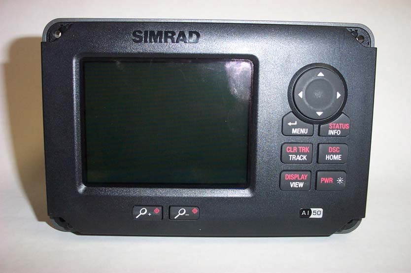
GL7AI50
Oct 02, 2008Class B AIS transponder
Equipment Class
AIS - Automatic Identification Systems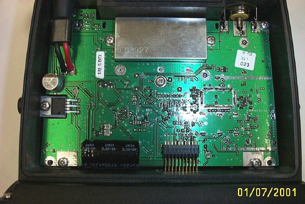
GL7RT63
Jul 08, 2001RT63 VHF marine Radiotelephone with DSC interface
Equipment Class
TNB - Licensed Non-Broadcast Station TransmitterGL7RD68
Dec 18, 2000VHF Marine radiotelephone inc class 'D' DSC controller
Equipment Class
TNB - Licensed Non-Broadcast Station Transmitter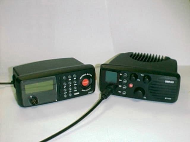
GL7DSC1400
Jul 15, 1999RT1400 + DSC1400
Equipment Class
TNB - Licensed Non-Broadcast Station Transmitter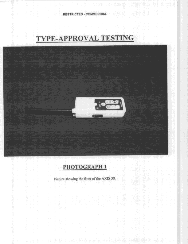
GL7AXIS30
Nov 08, 1998GVH - Part 80 VHF Transmitter (GMDSS)
Equipment Class
GVH - Part 80 VHF Transmitter (GMDSS)