GL7RD68VHF Marine radiotelephone inc class 'D' DSC controller
Navico UK LtdApplication Details
- Equipment Class
- TNB - Licensed Non-Broadcast Station Transmitter
- Date of Grant
- Dec 18, 2000
- Application Purpose
- Original Equipment
- Date of Application
- Oct 24, 2000
- Equipment Note
- VHF Marine radiotelephone inc class 'D' DSC controller
- Frequency Range
- 157.52500000 - 157.52500000
- Company
- Navico UK Ltd
- Country
- United Kingdom
Documents & Files
Document Text
Text extracted from the exhibit documents filed with the FCC. Open a document above to read the original.
Users Manual
Manual Simrad RD68 Fixed DSC VHF Radio RD68 Part No. E03912 Issue 1.0 28/6/00 MDL The technical data, information and illustrations contained in this publication were to the best of our knowledge correct at the time of going to print. We reserve the right to change specifications, equipment, installation and maintenance instructions without notice as part of our policy of continuous development and improvement. No part of this publication may be reproduced, stored in a retrieval system or transmitted in any form, electronic or otherwise without prior permission from Simrad Navico Ltd. No liability can be accepted for any inaccuracies or omissions in the publication, although every care has been taken to make it as com- plete and accurate as possible. © 2000 Simrad Navico Ltd Instruction Manual CONTENTS 1. GENERAL 1.1Introduction . . . . . . . . . . . . . . . . . . . . . . . . . . . . . . . . . . . . . . . . 4 1.2Licensing . . . . . . . . . . . . . . . . . . . . . . . . . . . . . . . . . . . . . . . . . . . 5 1.3Entering MMSI numbers . . . . . . . . . . . . . . . . . . . . . . . . . . . . . . 6 2. MAIN FUNCTIONS 2.1General . . . . . . . . . . . . . . . . . . . . . . . . . . . . . . . . . . . . . . . . . . . . 8 2.2Rotary controls . . . . . . . . . . . . . . . . . . . . . . . . . . . . . . . . . . . . . . 8 2.3Backlighting . . . . . . . . . . . . . . . . . . . . . . . . . . . . . . . . . . . . . . . . 9 2.4Changing channel . . . . . . . . . . . . . . . . . . . . . . . . . . . . . . . . . . . . 9 2.4.1 Standard International channel . . . . . . . . . . . . . . . . . . . . 9 2.4.2 Auxiliary & Private channels . . . . . . . . . . . . . . . . . . . . . 10 2.5Transmit power . . . . . . . . . . . . . . . . . . . . . . . . . . . . . . . . . . . . . 11 2.6Making a DSC call . . . . . . . . . . . . . . . . . . . . . . . . . . . . . . . . . . . 11 2.7Sending a Distress Alert call . . . . . . . . . . . . . . . . . . . . . . . . . . . 14 2.8Receiving a DSC call . . . . . . . . . . . . . . . . . . . . . . . . . . . . . . . . . 16 2.9Dual Watch . . . . . . . . . . . . . . . . . . . . . . . . . . . . . . . . . . . . . . . . . 17 2.10 Tri Watch . . . . . . . . . . . . . . . . . . . . . . . . . . . . . . . . . . . . . . . . . . . 18 2.11Scan Mode . . . . . . . . . . . . . . . . . . . . . . . . . . . . . . . . . . . . . . . . . . 19 2.11.1 Inhibit / enable channel from scan . . . . . . . . . . . . . . . . . 19 2.12 Memory scan . . . . . . . . . . . . . . . . . . . . . . . . . . . . . . . . . . . . . . . 20 2.12.1 Add / remove memory scan channels . . . . . . . . . . . . . . 21 2.13 Priority channel & user channel select . . . . . . . . . . . . . . . . . . . 22 2.13.1 Programming user channel . . . . . . . . . . . . . . . . . . . . . . . 22 2.14 Viewing call log . . . . . . . . . . . . . . . . . . . . . . . . . . . . . . . . . . . . . 23 3. MISCELLANEOUS FUNCTIONS 3.1Adjusting LCD contrast . . . . . . . . . . . . . . . . . . . . . . . . . . . . . . . 24 3.2Entering manual position & time . . . . . . . . . . . . . . . . . . . . . . . 25 3.3Entering local time . . . . . . . . . . . . . . . . . . . . . . . . . . . . . . . . . . . 27 3.4Viewing the directory . . . . . . . . . . . . . . . . . . . . . . . . . . . . . . . . . 28 3.4.1 Adding entry to directory . . . . . . . . . . . . . . . . . . . . . . . . 29 3.4.2 Editing / deleting entry . . . . . . . . . . . . . . . . . . . . . . . . . 30 3.5Disabling key beep . . . . . . . . . . . . . . . . . . . . . . . . . . . . . . . . . . . 32 3.6Second channel mode . . . . . . . . . . . . . . . . . . . . . . . . . . . . . . . . 33 3.7Speaker mute (handset models only) . . . . . . . . . . . . . . . . . . . . 33 4. INSTALLATION 4.1VHF installation . . . . . . . . . . . . . . . . . . . . . . . . . . . . . . . . . . . . . 34 4.2Antenna installation recommendations . . . . . . . . . . . . . . . . . . 37 4.3Electrical interference suppression . . . . . . . . . . . . . . . . . . . . . . 39 5. APPENDIX 5.1Operating procedures . . . . . . . . . . . . . . . . . . . . . . . . . . . . . . . . 40 5.2Transmission range . . . . . . . . . . . . . . . . . . . . . . . . . . . . . . . . . . 42 5.3Frequency of channels . . . . . . . . . . . . . . . . . . . . . . . . . . . . . . . . 43 5.4Fault finding . . . . . . . . . . . . . . . . . . . . . . . . . . . . . . . . . . . . . . . . 44 5.5Optional accessories . . . . . . . . . . . . . . . . . . . . . . . . . . . . . . . . . . 45 5.6Technical specification . . . . . . . . . . . . . . . . . . . . . . . . . . . . . . . . 46 5.7Dimensions . . . . . . . . . . . . . . . . . . . . . . . . . . . . . . . . . . . . . . . . . 47 5.8Service & warranty . . . . . . . . . . . . . . . . . . . . . . . . . . . . . . . . . . . 48 1 GENERAL 1.1 Introduction The RD68 is a combined VHF radio and Class D Digital Selective Calling (DSC) unit. It supports the latest GMDSS requirements for non-SOLAS vessels from the International Maritime Organisation (IMO). It will enable you to make digi- tally selected calls, which are quicker and simpler to make than traditional voice calls using Channel 16. Should a distress situ- ation occur, with the RD68 you can quickly raise an alert, indi- cating your identity, your position and automatically establish distress communication on the emergency voice channel. The RD68 is robustly constructed using a pressure die cast alu- minium case for effective heat dissipation, ensuring maximum transmission performance even after many hours constant use. Thank you for choosing Simrad If you are pleased with your VHF we hope you will be interest- ed in our range of marine electronic equipment, which is man- ufactured to the same high standards as the RD68. Please con- tact your nearest Simrad Agent for a catalogue showing our increasing range of high tech navigational instruments, GPS, autopilots, Radar, Fishfinders and VHF radio sets. Simrad operate a policy of continual development and reserve the right to alter and improve the specification …
Text truncated - open the document above for the full version.
Operational Description
SIMRAD-NAVICO CIRCUIT DESCRIPTION Circuit Diagram Part Number(s)Page 1 of 3 E02955 : Rx / TxDate: 15/6/00 Issue No. : 1 Product : RT1200 / RT1400 / RD68W Approved ............ References: E02955 schematic diagram. Overview: The Rx / Tx assembly is the transceiver half of the RD68W 25W mobile radiotelephone. It contains all the circuitry required to receive and transmit signals in the marine band. Circuit Description: Receiver.RF from the antenna socket passes through the low pass PA filter to a quarter wave match / switch L5, L6 and pin diode D1. During transmissions, D1 is switched on to protect the receiver. There then follows an optional attenuator and power splitter, to provide RF to the second receiver in the RT1400, which is bypassed by link LK1 in the RT1200. C214 is a 1nF coupling capacitor and L7, L8 and the associated capacitors form a bandpass filter at the input to the RF pre-amplifier TR1. L9 and L11 form a further bandpass section before the mixer TR2. The RF signal is fed to TR2 Source and the local oscillator to Gate 1. Low side injection is used, i.e. the LO, TR105 buffered by TR103 and TR104, is 21.4 MHz below the receive frequency. L13 forms the drain load before matching through C25 and C26 to the 4 pole crystal filter XTAL1 and XTAL2. The output of the filter is coupled by L14, C28 and C29 to the integrated IF amplifier / demodulator IC1. A second local oscillator running at 21.855MHz produces the second IF of 455KHz. XTAL4 is a 6 pole ceramic filter completing the necessary bandwidth definition with quadrature coil L16 providing demodulation. Audio from pin 9 of IC1 is de-emphasised by R20 and C43, buffered by TR20 and distributed to the various audio stages on the control PCB. The audio from pin 9 is also passed through a very high gain amplifier, within IC1 and configured as a bandpass filter, to detector D2 to provide a voltage proportional to the received signal strength. This level is fed to the front panel to provide squelch control. The AF signal is returned from the control panel after the volume and squelch controls to 2 audio power amplifiers in bridge mode. Transmitter.The LO switch / buffer TR102 switches the transmit signal for amplification by controlled transistors TR101 and TR100 to drive the hybrid PA module IC100 which is capable of generating the required 25 Watts. The output is switched through PIN diode D100 before passing through the PA filter L1 to L4. L4 of this filter, with diodes D101 and D102, forms a simple forward and reverse power detector to provide power control and transmitter status indication on the front panel display. The power control signal is fed to differential amplifier IC101 together with the reference power signal from VR100 and VR101, to set the high and low power levels. The output of this amplifier forms a regulated supply with TR113 and TR114 to supply the PA SIMRAD-NAVICO CIRCUIT DESCRIPTION Circuit Diagram Part Number(s)Page 2 of 3 E02955 : Rx / TxDate: 15/6/00 Issue No. : 1 Product : RT1200 / RT1400 / RD68W Approved ............ drivers TR100 and TR101. The reference input and supply for TR114 is fed from TR111 which is only turned on after the synthesiser is in lock. Local Oscillator / Synthesiser.The main LO consists of TR105 connected as a Colpitts oscillator. Tuning is by L113, varactor VC102 and VC104. Band switching between receive and transmit is by PIN diode D103. The output of the oscillator is buffered by a cascade pair formed by TR104 and TR103 in receive and TR102 and TR104 in transmit., the supply to TR102 and TR103 being switched between the 2 modes. The output is also buffered by TR118 to the input of the synthesiser IC105. The reference frequency at 9.6 MHz is generated by TR119 and controlled by XTAL101. C200, C115 and R157 form the main loop filter with additional suppression of the reference frequency by R179 and C204. The synthesiser is controlled from the control panel via a 3 wire serial interface. Modulator. Audio from the control panel is amplified by IC104b, the gain being configured by R169, R173 and C169 to give the signal pre-emphasis. The output of the stage is peak detected by D3 and detector TR1167 to provide a gain control signal to TR117 to enable limiting of high level input signals. Temperature compensation of the limiter is provided by thermistor TH1 and IC104a forms a high pass filter to meet the 14dB / octave roll-off above 6kHz. The final output is fed to the modulation diode VC101 via gain control VR102 which is set to a maximum of 5kHz deviation. Power Regulation and Switching.The 12 volt supply is switched on the front panel and then feeds the audio amplifiers and regulators. The RF power module takes power before the switch to minimise voltage drops. Reverse polarity protection is provided by D104 and D105. A regulated 8v supply is provided by IC103 and 5v from IC107. The supplies for receive and transmit circuits are switched by TR106 and TR110 controlled form the synthesiser via TR107 to TR109. IC105 controls the switching of PIN diode D103 ensuring that there is a suitably high reverse bias across it in the OFF condition. NMEA Reception.(RD68W only) Position and time information, from a GPS unit, is received in the form of NMEA data. This is opto-coupled into the radio via R225, D5 and IC4. The data is then routed through to the control PCB via PLG3. SIMRAD-NAVICO CIRCUIT DESCRIPTION Circuit Diagram Part Number(s)Page 3 of 3 E02955 : Rx / TxDate: 15/6/00 Issue No. : 1 Product : RT1200 / RT1400 / RD68W Approved ............ 2 1 . 4 M H z V C O & B u f f e r s S y n t h L o c k D e t e c t I F C h i p P r e - e m p h a s i s , L i m i t i n g & H P F - + D 1 , D 1 0 0 T R 2 T R 1 X T A L 3 X T A L 1 , 2 D 1 0 1 , 1 0 2 I C 1 0 1 , T R 1 1 3 , 1 1 4 T R 1 0 2 - 1 0 5 , V C 1 0 1 , 1 0 2 , 1 0 4 D 1 0 3 I C 1 0 4 , D 3 , T R 1 1 6 , 1 1 7 V R 1 0 0 V R 1 0 1 T R 1 1 2 X T A L 4 D 2 I C 1 T R 1 2 0 I C 1 0 5 T R 1 1 9 T R 1 0 1 T R 1 0 0 I C 2 I C 3 T R 1 1 5 , 1 1 1 I C 1 0 …
Text truncated - open the document above for the full version.
Operational Description
SIMRAD-NAVICO CIRCUIT DESCRIPTION Circuit Diagram Part Number(s)Page 1 of 3 E03656 : Front PanelDate: 15/6/00 Issue No. : 1 Product: RD68W Approved ............ References: E03656 schematic diagram. Overview: The front panel of the RD68W 25W mobile radiotelephone houses all the control circuitry for the radio. This includes; an 8-bit microcontroller, user controls and interfaces, display module, ATIS detection and mute circuitry. The front panel also incorporates a full class D DSC controller, by use of a V.23 modem. Circuit Description: All the functions of the radio are controlled from this assembly by the microprocessor IC4. The microprocessor has it own clock controlled by XTAL1 running at 7.15909MHz. Reset generator IC9 ensures that the microprocessor starts up correctly, and resets under low voltage conditions. The microprocessor has a data bus interface driving the front panel display module. External controls consist of a 21 push button key matrix, rotary squelch and volume control VR1 and VR3 respectively. The level of illumination on the LCD and keypad is controlled by TR7 driving LED’s 1 to 10 and the integral LED’s on the LCD module. Configuration data, MMSI and channel information is stored in the non volatile memory IC5. This interfaces to IC4 via a 4 wire serial interface shared with the synthesiser data to the Rx / Tx PCB assembly. Separate enables ensure that the data is routed correctly. Volume control VR3 controls the level of audio in the loudspeaker. Amplifier IC2a boosts the level delivered to the handset earpiece. Individual mutes of the handset and speaker audio are provided by TR3 and TR4 respectively, under control of the microprocessor. The voltage on the squelch control and noise input from the Rx/Tx PCB are read and the audio muted as appropriate. Additionally the state of the handset is detected from SKT1 to mute the speaker when the handset is off cradle (optional). The handset interface is via connector SKT1. The microphone input is biased for use with Electret microphones and may be muted by IC1a. The 12V output is current limited by TR5 and TR6. The cradle and PTT lines are also used for external data connections to a PC or third party accessories. Data interfaces are provided for external programming via TR1 and TR2. NMEA data is received from the Rx/Tx PCB via PLG2 and passed onto the microprocessor, IC4, via IC1c. SIMRAD-NAVICO CIRCUIT DESCRIPTION Circuit Diagram Part Number(s)Page 2 of 3 E03656 : Front PanelDate: 15/6/00 Issue No. : 1 Product: RD68W Approved ............ Optional circuitry for ATIS detection consists of IC6, IC7, D1 and TR8.The inclusion of IC7 allows the ATIS signal to be muted during reception. The received audio is filtered by IC6c and IC6d which are followed by a zero crossing detector formed by IC6a, IC6b, D1 and TR8. This signal is sent to a second microprocessor, IC7, which measures the period of each half cycle of the incoming signal. By counting the number of periods which might be an ATIS signal the micro can decide whether ATIS is being received or not. When this decision is made, after about 10ms, IC7 sets an output to inform IC4 to mute the audio for 300ms. IC7 derives its clock and reset from the main microprocessor IC4. The ATIS and DSC signals are generated and decoded by the modem, IC8 and surrounding components. TR9 switches the modulation index between that required for DSC and ATIS. The output signal is then passed onto the microphone audio via IC1b. Note that the microphone is muted by IC1a during transmission of the ATIS or DSC signals. The audio level required for alarms is controlled by IC1d. For normal key ‘beeps’ the microprocessor, IC4, generates a square wave which is filtered and reduced in level by R15, R75, C14 and C105 and then fed into the audio amplifier via PLG1. For alarm generation IC1d short circuits R75 to increase the level of signal being fed to the audio amplifier. SIMRAD-NAVICO CIRCUIT DESCRIPTION Circuit Diagram Part Number(s)Page 3 of 3 E03656 : Front PanelDate: 15/6/00 Issue No. : 1 Product: RD68W Approved ............ R e v e r s e P o w e r C a r r i e r P o w e r E a r p i e c e A u d i o A n a l o g u e 0 V A F O u t A F I n S q u e l c h L e v e l P T T / D a t a O u t L C D M o d u l e R e s e t 7 . 1 5 9 0 9 M H z C l o c k , D a t a & E n a b l e s M o d o u t M i c i n I C 7 M a i n C P U I C 4 I C 6 a , b I C 6 c , D 1 , T R 8 T R 3 T R 4 1 V R 3 S q u e l c h V R 1 I C 2 a I C 9 T R 1 , T R 2 K e y M a t r i x I C 1 c N M E A I C 8 D S C i n I C 1 a I C 1 b I C 1 d F X 6 0 4
Operational Description
SIMRAD-NAVICO CIRCUIT DESCRIPTION Circuit Diagram Part Number(s)Page 1 of 2 E03209 : Second ReceiverDate: 15/6/00 Issue No. : 1 Product: RT1400 / RD68W Approved ............ References: E03209 schematic diagram. Overview: The second receiver is purely a watchdog receiver. Dedicated to listen in on channel 70, for any DSC signals. Circuit Description: The second receiver is connected to the main receiver at the power splitter L10, C215, C214 and R205. The basic circuitry is the same as the receiver section of the main receiver. L300, L301 and associated capacitors form the input bandpass section, prior to the RF amplifier TR300. A second bandpass section is formed by L302 and L303, which couple into the mixer at the source of TR301. Low side injection from the local oscillator is fed into the gate. The output at 17.9MHz passes through the crystal filter XTAL300 and XTAL301 to the second IF stage, IC300. Demodulated audio is buffered by IC302a. TR304 and XTAL304 form the reference oscillator for the synthesiser, IC301. Data from the front panel is fed from Clock, Data and Enable 2. C350, C355 and R345 form the basic loop filter to control the frequency of the local oscillator, TR303, by varactor VC301. The output of the local oscillator is buffered by TR302 before being coupled to the mixer through band bass filter L307 and L308. SIMRAD-NAVICO CIRCUIT DESCRIPTION Circuit Diagram Part Number(s)Page 2 of 2 E03209 : Second ReceiverDate: 15/6/00 Issue No. : 1 Product: RT1400 / RD68W Approved ............ 1 7 . 9 M H z V C O & B u f f e r S y n t h I F C h i p T R 3 0 1 T R 3 0 0 X T A L 3 0 2 X T A L 3 0 0 , 3 0 1 T R 3 0 2 , 3 0 2 , V C 3 0 1 X T A L 3 0 3 I C 3 0 0 I C 3 0 2 I C 3 0 1 T R 3 0 5 X T A L 3 0 4 O s c D S C A F O u t C l o c k D a t a E n a b l e 2 R F f r o m m a i n R x - T x B o a r d
Test Report
NAVIGATION AND COMMUNICATION SYSTEMS REPORT FORM FOR TESTING TO EN 301 025 RADIO EQUIPMENT AND SYSTEMS RADIOTELEPHONE TRANSMITTERS AND RECEIVERS FOR THE MARITIME MOBILE SERVICE OPERATING IN THE VHF BANDS TECHNICAL CHARACTERISTICS AND METHODS OF MEASUREMENT Test Report Number: TAR001 Simrad Navico Ltd Test Report to EN 301-025 CONTENTS Page Section 1 Introduction.............................................................3 Section 2Product.....................................................................4 Section 3Test Schedule...........................................................4 Section 4Test Technical Details....................................................5 Section 5Summary of Tests.................................................................6 Section 6 General and operational requirements....................................... 8 Section 7 Technical Requirements.................................................. 12 Section 8 Enviromental Test Results....................................................16 Section 9Transmitter Test Results.......................................................20 Section 10 Receiver Test Results........................................................38 Section 11DSC 2nd Receiver Test Results....................................53 Section 12Test Equipment List..................................................62 Section 13Measurement Scan Results..............................................63 Section 14 Photographs of EUT............................................................66 Page 2Test Report Number: TAR001 Simrad Navico Ltd Test Report to EN 301-025 SECTION 1 INTRODUCTION This report contains the results of tests performed on the product RD68 VHF radio with DSC & ATIS, on this premises of : Simrad Navico Ltd Star Lane Margate Kent CT9 4NP Simrad Navico Ltd complies with the accreditation criteria requirements of the quality standards, BS EN ISO 9001:1994. The accreditation covers the quality system of the EMC test department as well as the, design,manufacture, distribution, aftersales, marketing and support of communications and marine electronics for the leisure, commercial and military markets, as described in the certificate of approval bearing the certificate number 21460 and granted on 3 december 1998 for a period of 3 years. All testing was carried out within the EMC test department of Simrad Navico Ltd, to the requirements of ETSI EN 301 025 V1.1.1 (1998-08). Testing carried out by:Kevin Heath Report checked by:David Sheekey Date:15/06/00 Modification Record DateMod Note Description 19/09/001463Change of decoupling. Re tested. See annex 1 26/10/00N/APart number changed from RD68 to RD68W which is released part number Page 3Test Report Number: TAR001 Simrad Navico Ltd Test Report to EN 301-025 SECTION 2 PRODUCT A sample of the following product was submitted for testing: Maritime Integraded VHF/DSC Radiotelephone with ATIS Manufacture:Simrad Navico Ltd Parts of Product:1 x RD68; Transceiver Unit with DSC controller & ATIS. 1 x Handset / Fistmike. Serial Number:TA Unit 3 Software Release:Issue 1 Particulars:DSC Class D SECTION 3 TEST SCHEDULE Tests were carried out in accordance with the specification detailed in clause 6 EN 301 025 document, "general conditions of measurement". All tests were carried out at Simrad Navico Ltd. The sample unit was tested between the following dates: 1st March 2000 - 14th April 2000. The RD68 VHF radio with DSC & ATIS, is intended for use in the following application area: MARINE COMMUNICATIONS EQUIPMENT Page 4Test Report Number: TAR001 Simrad Navico Ltd Test Report to EN 301-025 SECTION 4 TEST TECHNICAL DETAILS Test Unit = RD68 VHF Radio with DSC & ATIS Serial Number = TA UNIT 3 Additional Parts =Telephone handset / Fistmike Nominal Voltage = 12.0 Volts Maximum Voltage = 15.6 Volts Minimum Voltage = 10.8 Volts Nominal Temperature = 20°C Maximum Temperature = 55°C Minimum Temperature = -15°C Channel 16 = 156.800MHz Upper Frequency = 162.975MHz Lower Frequency = 155.025MHz Second Receiver Frequency = 156.525MHz Channel Spacing = 25.0kHz First IF Main Rx = 21.4MHz Second IF Main Rx = 455.0kHz First IF 2nd Rx = 17.9MHz Second IF 2nd Rx = 455.0kHz Rated Audio Power = 6.0 Watts( external speaker ) 2 mW( handset earphone ) Rated Audio Load = 4 Ohms( external speaker ) 300 Ohms( handset earphone ) Page 5Test Report Number: TAR001 Simrad Navico Ltd Test Report to EN 301-025 SECTION 5 SUMMARY OF TEST RESULTS Clause NoGeneral and operational requirementsComplies? 4.1 General Yes 4.2 Composition Yes 4.3 Construction Yes 4.4 Controls and indicators Yes 4.5 Facilities for coding and decoding of DSC Yes 4.5.1 Call functions Yes 4.5.2 Manual calls Yes 4.5.3 Distress calls Yes 4.5.4 All ships calls Yes 4.5.5 Incoming calls Yes 4.6 DSC display Yes 4.7 Handset and loudspeaker Yes 4.8 Safety precautions Yes 4.9 Labelling Yes 4.10 Warm up Yes Technical Requirements 5.1 Switching time Yes 5.2 Class of emission and modulation characteristics Yes 5.3 Facilities for DSC transmission and reception Yes 5.3.1 General Yes 5.3.2 Decoding Yes 5.3.3 Free channel transmission Yes 5.3.4 Automatic acknowledgement Yes 5.3.5 Automatic re-transmission of distress calls Yes 5.4 Ships identity - MMSI and group MMSI Yes 5.5 Entry of position information Yes 5.6 Alarm circuits Yes 5.6.1 Distress and urgency Yes 5.6.2 Other categories Yes 5.6.3 Acoustic alarms Yes 5.6.4 Cancellation of alarms Yes 5.7 Facilities for automatic identification Yes 5.8 Multiple watch facilities Yes 5.8.1 General Yes 5.8.2 Scanning provisions Yes 5.8.3 Scanning characteristics Yes Enviromental Tests 7.4 Vibration Yes 7.5 Temperature Tests Yes 7.5.2 Dry heat Yes 7.5.3Damp HeatYes 7.5.4Low temperatureYes Page 6Test Report Number: TAR001 Simrad Navico Ltd Test Report to EN 301-025 5 SUMMARY OF TEST RESULTS (continued) Clause No.TransmitterComplies? 8.1 Transmitter Frequency Error Yes 8.2 Transmitter Carrier Power Yes 8.3 Transmitter Frequency Deviation Yes 8.3.3 …
Text truncated - open the document above for the full version.
Test Report
NAVIGATION AND COMMUNICATION SYSTEMS REPORT FORM FOR TESTING TO EN 300 828 ELECTROMAGNETIC COMPATIBILITY AND RADIO SPECTRUM MATTERS (ERM) ELECTROMAGNETIC COMPATIBILITY (EMC) FOR RADIOTELEPHONE TRANSMITTERS AND RECEIVERS FOR THE MARITIME MOBILE SERVICE OPERATING IN THE VHF BANDS Simrad Navico Ltd Test Report to EN 300-828 CONTENTS Page Section 1 Introduction.....................................................................3 Section 2Product...........................................................................4 Section 3Test Schedule.................................................................4 Section 4Test Technical Details.......................................................5 Section 5 Summary of Tests............................................................6 Section 6 Results........................................................................... 7 Section 7 Test Equipment List........................................................13 Section 8Measurement Scan Results...............................................14 Section 9Photographs of EUT..........................................................20 Page 2 Simrad Navico Ltd Test Report to EN 300-828 SECTION 1 INTRODUCTION This report contains the results of tests performed on the product RT1800 VHF radio with DSC, on this premises of : Simrad Navico Ltd Star Lane Margate Kent CT9 4NP Simrad Navico Ltd complies with the accreditation criteria requirements of the quality standards, BS EN ISO 9001:1994. The accreditation covers the quality system of the EMC test department as well as the, design,manufacture, distribution, aftersales, marketing and support of communications and marine electronics for the leisure, commercial and military markets, as described in the certificate of approval bearing the certificate number 21460 and was granted on 3 december 1998 for a period of 3 years. All testing was carried out within the EMC test department of Simrad Navico Ltd, to the requirements of EN 300 828 V1.1.1 (1998-03). Testing carried out by:.............................................. Report checked by:.............................................. Date:...................... Page 3 Simrad Navico Ltd Test Report to EN 300-828 SECTION 2 PRODUCT A sample of the following product was submitted for testing: Maritime Integraded VHF/DSC Radiotelephone with ATIS Manufacture:Simrad Navico Ltd Parts of Product:RT1800; Transceiver Unit with DSC controller & ATIS. Handset or Fistmike. Serial Number:TA Unit 3 Software Release:Issue 1 Particulars:DSC Class D SECTION 3 TEST SCHEDULE All tests were carried out within the EMC department at Simrad Navico Ltd. The sample unit was tested between the following dates: 1st March 2000 - 14th April 2000. The RT1800 VHF radio with DSC & ATIS, is intended for use in the following application area: MARINE COMMUNICATIONS EQUIPMENT; and was tested to ETSI EN 300 828 V1.1.1(1997-12). The following tests shown below were carried out on a sample of the RT1800 VHF radio with DSC & ATIS Test ClauseDescription of TestDate of Test 8.1.2.1Radiated Emissions (150kHz-30Mhz)27/03/00 8.2DC Power Ports27/03/00 9.1RF Electromagnetic Field (80Mhz-1Ghz)05/04/00 9.2Electrostatic Discharge14/04/00 9.4Conducted disturbances induced by RF fields (150Khz-80Mhz)05/04/00 9.6Power Supply Failure05/04/00 Excempt from Testing Test ClauseDescription of TestReason This test is covered by EN 301 025 V1.1.1 (1998-08), See test report for RT1800 VHF radio with DSC & ATIS to EN 301 025. This test was not conducted as no cables were longer than 3 metres. This test is required on AC power input ports only, the RT1800 requires a 12v DC input only, therefore is excempt. This test is required on AC power input ports only, the RT1800 requires a 12v DC input only, therefore is excempt. Radiated Emissions (30Mhz-1Ghz) Fast Transient Power Supply Short Term Vari Surge 8.1.2.2 9.3 9.5 9.7 Page 4 Simrad Navico Ltd Test Report to EN 300-828 SECTION 4 TEST TECHNICAL DETAILS Test Unit = RT1800 VHF Radio with DSC & ATIS. Serial Number = TA UNIT 3 Additional Parts = Telephone handset / Fistmike Nominal Voltage = 12.0 Volts Nominal Temperature = 20°C Channel 16 = 156.800MHz Upper Frequency = 162.975MHz Lower Frequency = 155.025MHz Second Receiver Frequency = 156.525MHz Channel Spacing = 25.0kHz First IF Main Rx = 21.4MHz Second IF Main Rx = 455.0kHz First IF 2nd Rx = 17.9MHz Second IF 2nd Rx = 455.0kHz Rated Audio Power = 6.0 Watts( external speaker ) 2 mW( handset earphone ) Rated Audio Load = 4 Ohms( external speaker ) 300 Ohms( handset earphone ) Page 5 Simrad Navico Ltd Test Report to EN 300-828 SECTION 5 SUMMARY OF TEST RESULTS Clause NoDescription of TestComplies? 8.1.2.1 Radiated Emissions (150kHz-30Mhz)Yes 8.1.2.1 Radiated Emissions (30Mhz-1Ghz)Yes* 8.2 DC power in/outYes 9.1 RF electromagnetic field (80Mhz-1Ghz)Yes 9.2 Electrostatic DischargeYes 9.3 Fast TransientsYes* 9.4 Conducted disturbances induced by RF fields (150Khz-80Mhz)Yes 9.5 Power Supply Short Term VariationsYes* 9.6 Power Supply FailureYes 9.7 SurgeYes* Note: * = See Section 3 (excempt from testing) The test sample of RT1800 VHF radio with DSC & ATIS has successfully passed a series of tests to EN 300 828 V1.1.1(1998-03), which indicate its compliance with the EMC criteria of ETSI EN 300 828 V1.1.1 (1998-03). Page 6 Simrad Navico Ltd Test Report to EN 300-828 SECTION 6 RADIATED EMISSIONSClause :8.1 Definition:This test assesses the ability of the EUT to limit unwanted emissions from the enclosure. Product:RT1800 VHF radio with DSC & ATIS Method:As per EN 300-828, clause 8.1.2.1. Resul…
Text truncated - open the document above for the full version.
Contact Information
Applicant
David C. Sheekey(Product Expert)
Technical Contact
Simrad-Navico LtdDavid C Sheekey
[email protected]+44 (0)1843 290290
Star Lane · Kent · United Kingdom
Technical Specifications
| # | Rule Parts | Frequency Range | Power Output | Emission | Tolerance |
|---|---|---|---|---|---|
| 3 | 8 | 157.525 MHz - 157.525 MHz | 25 W | 16K0G2B | 10 ppm |
Other Applications from Navico UK Ltd
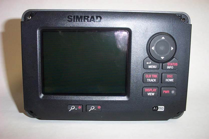
GL7AI50
Oct 02, 2008Class B AIS transponder
Equipment Class
AIS - Automatic Identification Systems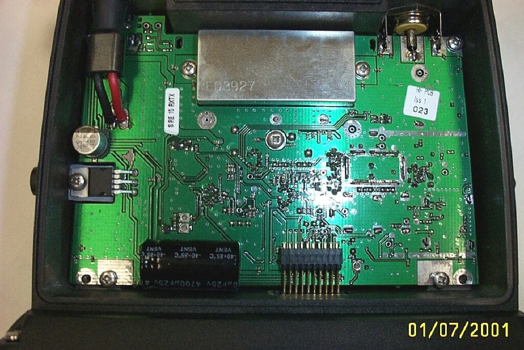
GL7RT63
Jul 08, 2001RT63 VHF marine Radiotelephone with DSC interface
Equipment Class
TNB - Licensed Non-Broadcast Station Transmitter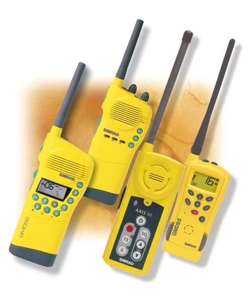
GL7AXIS50
Feb 16, 2000VHF handheld
Equipment Class
GHH - Part 80 VHF Hand Held Transmitter (GMDSS)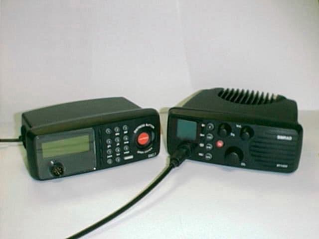
GL7DSC1400
Jul 15, 1999RT1400 + DSC1400
Equipment Class
TNB - Licensed Non-Broadcast Station Transmitter
GL7AXIS30
Nov 08, 1998GVH - Part 80 VHF Transmitter (GMDSS)
Equipment Class
GVH - Part 80 VHF Transmitter (GMDSS)