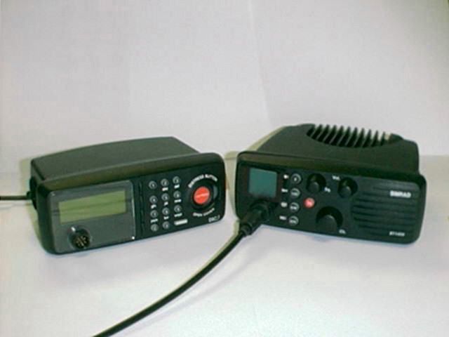
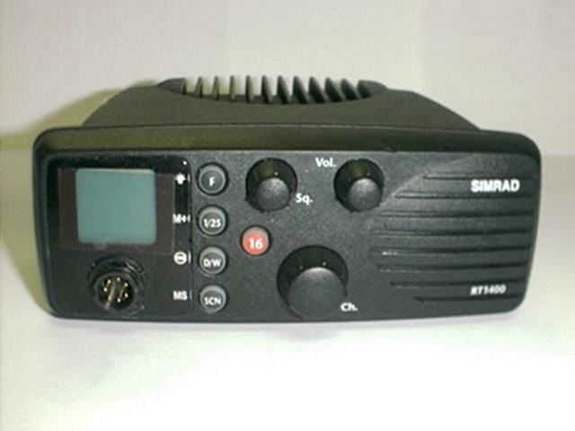
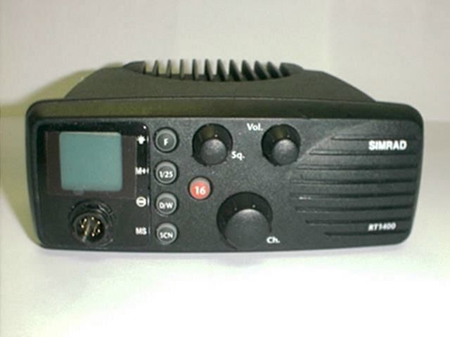
GL7DSC1400RT1400 + DSC1400
Navico UK Ltd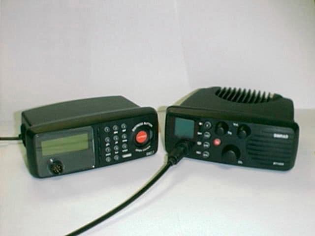
Click to zoom
Application Details
- Equipment Class
- TNB - Licensed Non-Broadcast Station Transmitter
- Date of Grant
- Jul 15, 1999
- Application Purpose
- Original Equipment
- Date of Application
- Jan 12, 1999
- Equipment Note
- RT1400 + DSC1400
- Frequency Range
- 156.00000000 - 157.50000000
- Company
- Navico UK Ltd
- Country
- United Kingdom
Documents & Files
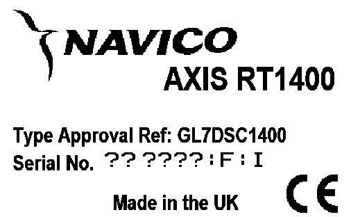
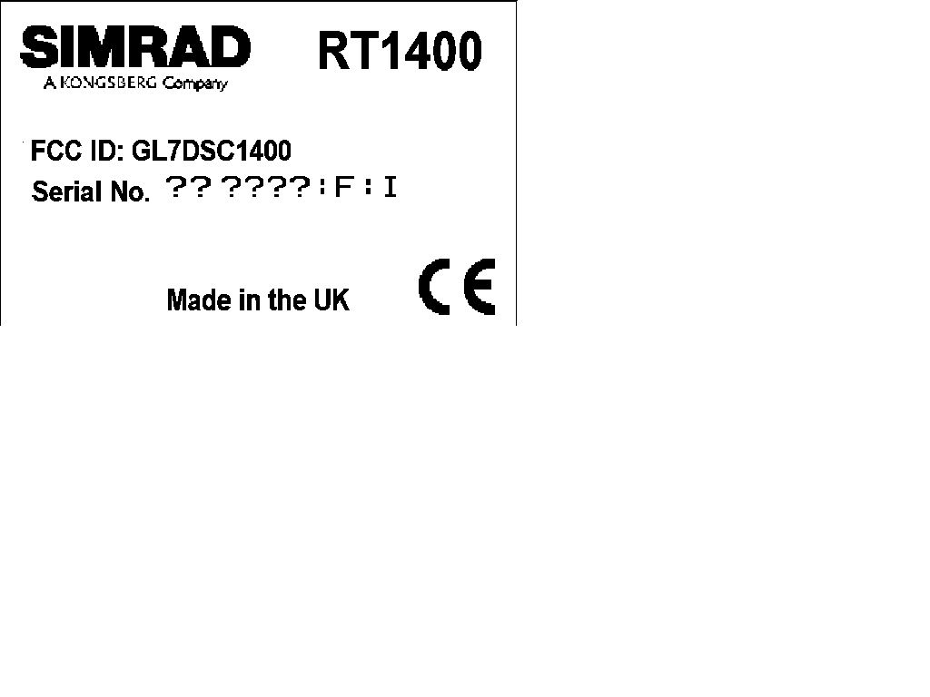
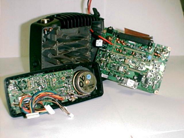
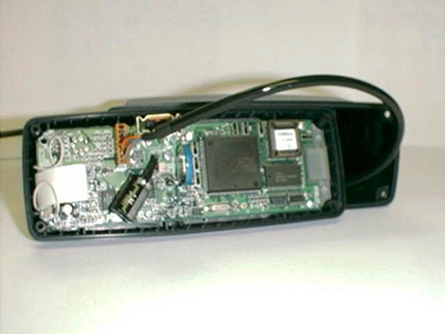
Document Text
Text extracted from the exhibit documents filed with the FCC. Open a document above to read the original.
Users Manual
Manual Navico RT1200 / RT1400 VHF Radio Page 2 The technical data, information and illustrations contained in this publication were to the best of our knowledge correct at the time of going to print. We reserve the right to change specifications, equipment, installation and maintenance instructions without notice as part of our policy of continuous development and improvement. No part of this publication may be reproduced, stored in a retrieval system or transmitted in any form, electronic or otherwise without prior permission from Simrad Navico Ltd. No liability can be accepted for any inaccuracies or omissions in the publication, although every care has been taken to make it as complete and accurate as possible. MDL 2/12/98 © 1998 Simrad Navico Ltd For service and advice please contact the main Simrad dealer in your country of residence. Page 3 CONTENTS 1. General 1.1 Introduction 1.2 RT1200 and RT1400 1.3 Technical Specification 1.4 Dimensions 1.5 Licensing 2. Operation 2.1 Location of Controls 2.2 Operation - Scanning Versions 2.2.1 Function (F) / Backlight ( ) 2.2.2 Power (1/25) / Channel Memory (M+) 2.2.3 Dual Watch (D/W) / Channel Inhibit ( ) + Revert function 2.2.4 Scan (SCN) / Memory Scan (MS) 2.2.5 Channel 16 (16) 2.2.6 Squelch (Sq) 2.2.7 Volume, On/Off (Vol) 2.2.8 Channel Select (Ch) 2.3 Operation - Non-scanning Versions 2.3.1 Backlight ( ) 2.3.2 Working Channel (P) 2.4 Memory Mode (Scanning versions only) 2.5 Second Channel Mode 2.6 Speaker Mute (Handset models only) 3. Installation 3.1 VHF Installation 3.2 Electrical Installation 3.3 Antenna Installation Recommendations 3.4 Electrical Interference Suppression 4.Appendix 4.1 Optional Accessories 4.2 Transmission Range 4.3 Frequency of Channels 4.4 Fault Finding 4.5 Service & Warranty Page 4 1 General 1.1 Introduction The RT1200 and RT1400 fixed VHF radio is designed by Simrad and manufactured at our modern factory facility in the UK. The radio is designed to meet or exceed stringent International Regulations including ETS300-162. The RT1200 and RT1400 are robustly construct- ed using a pressure die cast aluminium case for effective heat dissipation, ensuring maximum transmission performance even after many hours constant use. Please note that VHF regulations vary from country to country. Simrad sets are approved specifically by the countries in which they are sold and consequently there may be differences in the programming of sets bought in different countries. If using outside the country of pur- chase, it is vital to check that the set conforms to local regulations before use. Thank you for choosing Simrad If you are pleased with your VHF we hope you will be interested in our range of marine elec- tronic equipment, which is manufactured to the same high standards as the RT1200/1400. Please contact your nearest Simrad Agent for a catalogue showing our increasing range of high tech navigational instruments, GPS, autopilots, Radar, Fishfinders and VHF radio sets. Simrad operate a policy of continual develop- ment and reserve the right to alter and improve the specification of their products without notice. F 16 1/25 D/W SCN Sq Vol M+ MS RT1200 & RT1400 Waterproof Fixed VHF OR Page 5 1.2 RT1200 and RT1400 The Simrad fixed VHF range consists of two models - the RT1200 and RT1400. Both are available with either a fistmike or telephone handset, and offer the same features including channel scan, channel memory, dual watch etc. The details in this owner ’s manual apply to both models. The RT1400 model features an additional watchkeeping receiver, allowing it to use the Digital Selective Calling (DSC) system for routine and distress calling on VHF channel 70. For this the RT1400 will need to be linked to the Simrad DSC control unit DSC1400(DSC Class D). DSC com- patibility is not available with the RT1200 model. This manual describes all operating features available to the RT1200 and RT1400 models, includ- ing channel scan, which is not permitted in certain countries. Therefore this feature may not be available on the set supplied if it was purchased or configured for one of these countries. 1.3 Technical Specification Power Supply12v DC (10.8v - 15.5v DC) Channel Capability55 international channels 1-28, 60-88 simplex & semi-duplex UK : includes M (previously 37) and M2 USA : includes 0, 29, 89, 75, 76, Wx1-10 receive only. Scandinavia : leisure or fishing channels as appropriate. Canada : Canadian and USA channels. Private ChannelsUp to 16 private channels* External Speaker Impedance8Ω Transmit - Frequency Range155-163Mhz Power Output1 watt or 25 watts Current Consumption5.5A (25 watts) 1.3A (1 watt) Harmonic and Spurious Emissions < 0.25μW Hum / Noise< -40dB Modulation±5kHz Receive Audio Output Power6 watts Current Consumption300mA (Full Volume, illumination on) 180mA (Fully Squelched, illumination off) Sensitivity< 0.5μV emf for 20 dB SINAD Harmonic and Spurious Emissions < -2nW Hum / Noise< -40dB Adjacent Channel Selectivity70dB Intermodulation Rejection70dB * Contact local Simrad Technical Dealer for further details of channel programming etc. Environmental VHF RadioWaterproof to IP66 (IP67 when flush mounted) Fistmike / Telephone HandsetWaterproof to IP67 Page 6 F 16 1/25 D/W SCN Sq Vol M+ MS 1.4 Dimensions 185mm (7.4in) 158mm (6.2in) 66mm (2.6in) 22mm (0.9in) 47mm (1.8in) 55mm (2.2in) 79mm (3.1in) 213mm (8.4in) 54mm (2.2in) 70mm (2.8in) Page 7 1.5 Licensing Prior to use check the national licensing requirements for the operator. In the UK license applications and queries should be made to the following authority - Wray Castle Ship Radio Licensing PO Box 5 Ambleside LA22 0BF Tel - 01539 434662 A set may only be operated by, or under the supervision of a holder of a Certificate of Competence andAuthority to Operate. This involves a simple examination and an annual license renewal fee. The VHF only certificate is administered by the Royal Yachting Association - Royal Yachting Association RYA House Romsey Road Eastleigh Hants, …
Text truncated - open the document above for the full version.
Users Manual
Manual Navico DSC1400 Class D DSC Controller Page 2 The technical data, information and illustrations contained in this publication were to the best of our knowledge correct at the time of going to print. We reserve the right to change specifications, equipment, installation and maintenance instructions without notice as part of our policy of continuous development and improvement. No part of this publication may be reproduced, stored in a retrieval system or transmitted in any form, electronic or otherwise without prior permission from Simrad Navico Ltd. No liability can be accepted for any inaccuracies or omissions in the publication, although every care has been taken to make it as complete and accurate as possible. MDL 2/12/98 E02610 Issue 1.2 © 1999 Simrad Navico Ltd Simrad Navico Ltd Star Lane, Margate, Kent CT9 4NP, UK Telephone +44 (0) 1843 290290 Facsimile +44 (0) 1843 290471 E-Mail : [email protected] Page 4 1 General 1.1 Introduction The DSC1400 is a Class D Digital Selective Calling (DSC) Controller designed for use with the Axis RT1400 VHF radio. With a DSC1400 the RT1400 will support the latest GMDSS requirements for non-SOLAS vessels from the International Maritime Organisation (IMO). It will enable you to make digitally selected calls, which are quicker and simpler to make than traditional voice calls using Channel 16. Should a distress situation occur, with the DSC1400 you can quickly raise an alert, indicating your identity, your position and automatically establish distress communication on the emergency voice channel. Thank you for choosing Simrad If you are pleased with your DSC controller we hope you will be interested in our range of marine electronic equipment, which is manufactured to the same high standards as Axis. Please contact your nearest Simrad Agent for a catalogue showing our full range of high tech marine electronic equipment. Simrad Navico operate a policy of continual development and reserve the right to alter and improve the specification of their products without notice. Axis ® is a Registered Trade Mark of Simrad Navico Ltd DSC1400 Class D Digital Selective Calling Controller Page 6 1.3 MMSI Number For the DSC1400 to function an MMSI (Maritime Mobile Service Identifier) number will need to be entered. This can be obtained from the local radiocommunications authority. 1.4 Keypad The telephone style ITU keypad is used for entering numeric data. When required, the keys will automatically switch to character mode allowing letters, numbers and punctua- tion characters to be entered. Repeatedly pressing a key will cycle through the characters available on that key (Fig 1.2). The Cancel key will stop a task and return to the main screen. The ENTERkey is used to confirm actions, such as sending a call. 1.5 Softkeys The functions of the four softkeys - one for each line of the display (Fig 1.3) - will change to suit the menu that is currently displayed. A label indicating the function of the softkey will be displayed on the right side of the correspond- ing display line. 1.6 Distress Button The distress button is located under a protec- tive cover that must be lifted before the button can be pressed (Fig 1.4). THIS BUTTON MUST ONLY BE USED IN A DISTRESS SITUATION. Refer to section 2.5 for more details. 1.7 Working Channels While all DSC transmissions from the DSC1400 are made digitally on channel 70, once the call has been put through, communication with the other vessel or station will be via a normal voice channel, which is specified when the call is made. This is referred to in this manual as a working channel 0123456789 sp - ADG J MPT W ( , BEHKNQUX ) .CFILORVY %/?!:"'S&Z 1 Press 2 Presses 3 Presses 4 Presses 5 Presses Fig 1.2 - Keypad character map 1 4 7 C Fig 1.3 - Softkeys Softkeys Fig 1.4 - Distress Button 52º02’NCall 001º35’E 08:54 UTCLog Ch 06Menu Page 8 Press the ENTERkey to make the call. The DSC1400 will require confirmation of the call. Press Ye sto send the call, or Noto cancel. When the DSC call is sent, the RT1400 will be set to the working channel. Allow a few sec- onds for the stations receiving the call to switch to the working channel, then make a normal voice call on the specified working channel. 2.4 Group Call If a group ID has been set up for the DSC1400 (see section 4.7), a call can be made to other members of the group. Press the Callkey four times to select the Group Call screen. Select a working channel from the list (see section 4.10) by pressing the channel softkey or use the RT1400 channel select knob (Fig 1.7). Press ENTERto send the call, allow a few sec- onds for the other members of the group to reach their radios (all VHF radios in the group should automatically switch to the specified working channel upon acknowledgement), then make a normal voice call using the work- ing channel. 2.5 Distress Alert NOTE - THIS CALL SHOULD ONLY BE MADE IF THE VESSEL IS IN A DISTRESS SITUATION.It is an offense to send a Distress Alert call if the vessel or crew are not in danger. Refer to section 5.1 for more details. Lift the protective cover and press the DIS- TRESSbutton. The Distress Alert Screen will be displayed. If time permits, press the des- ignation softkey to select the nature of the dis- tress. There are 10 categories recognised as Distress Alert situations, which are - Abandoning, Adrift, Collision, Fire, Flooding, Grounding, Listing, Man Overboard, Piracy and Sinking. There is also a default Undesignated category, which is used if no cat- egory is selected here. Press and hold the DISTRESSkey a second 1 4 7 C Group call To 100000000 On 06 1 4 7 C 2 5 8 0 3 6 9 ENTER D I S T R E S S B U T T O O P E N C O V E R ENTER Fig 1.7 - Sending Group Call Page 10 3 Receiving A Call 3.1 General When a DSC call is received, the DSC1400 will switch to the call log screen to display the details of the call and ring or sound the alarm - depending on the nature of the call. The pro- cedures that follow describe how to handle the type…
Text truncated - open the document above for the full version.
Block Diagram
Circuit Description - AXIS RT1200/1400 Introduction. The AXIS RT1200 consists of two PCB assemblies. The main RF PCB assembly , Navico part No. E02957, contains all the transmitter and receiver circuitry, including the synthesiser, modulator and audio power amplifiers. The control PCB assembly, Navico part No. E02960, contains the microprocessor, user controls, the LCD display and external interfaces. The AXIS RT1400 has an additional Channel 70 watchkeeping receiver, Navico part No. E03211, fitted to the main Rx/Tx assembly. There are no differences to the front panel assembly in this version. E02957 Rx/Tx PCB Assembly. The circuitry on this assembly is shown on drawing No. E02955. Receiver. RF from the antenna socket passes through the low pass PA filter to a quarter wave match/switch L5, L6 and pin diode D1. In transmit D1 is on to protect the receiver. There then follows an optional attenuator and power splitter, not used on the RT1200. In this model C214 is a 1nF coupling capacitor. L7, L8 and the associated capacitors form a bandpass filter before the R.F. pre-amp, TR1. L9 and L11 form a further bandpass section before the mixer. The RF signal is fed to the source of TR2 and the local oscillator fed to Gate 1. Low side injection is used, i.e. the LO is 21.4 MHz below the receive frequency. L13 forms the drain load before matching through C25 and C26 to the 4 pole crystal filter, XTAL1 and XTAL2. The output of the filter is coupled by L14, C28 and C29 to the integrated IF amplifier/demodulator IC1. This uses a second local oscillator at 21.855MHz giving a second IF of 455kHz. XTAL4 is a 6 pole ceramic filter completing the necessary bandwidth definition. Quadrature coil L16 provides the demodulation. Audio from pin 9 of IC1 is de-emphasised by R20 and C43, buffered by TR120 before distribution to the various audio stages on the control PCB. The audio from pin 9 is also passed through a very high gain amplifier, within IC1, configured as a band pass filter to detector D2 to provide a voltage proportional to the received signal strength. This level also goes to the control panel to provide squelch control. The AF signal is returned from the control panel after the volume and squelch controls to two audio power amplifiers in Bridge mode. The speaker output is switched at the external speaker socket to mute the internal speaker when an external speaker is connected. Transmitter. From the LO switch/buffer TR102, the transmit signal is amplified by controlled transistors TR101 and TR100, to drive the hybrid PA module IC100. This device is capable of generating the required 25Watts. The output is switched through PIN diode D100 before passing through the PA filter L1 to L4. L4 of this filter, with diodes D101 and D102 forms a simple forward and reverse power detector to provide power control and transmitter status indication on the front panel display. The power control signal is fed to differential amplifier IC101 along with the reference power signal from VR100 and VR101, used to set the hi and low powers. The output of this amplifier forms a regulated supply with TR113 and TR114 to supply the PA drivers TR100 and TR101. Note that the reference input and supply for TR114 is fed from TR111 which is only turned on after the synthesiser is in lock. Local Oscillator / Synthesiser . The main LO consists of TR105 connected as a Colpitts oscillator. Tuning is by L113 and varactor VC102. Band switching between Rx and Tx is by PIN diode D103. The output of this oscillator is buffered by a cascade pair formed by TR104 and TR103 in receive, and TR102 and TR104 in Transmit, the supply to TR102 and TR103 being switched between the two modes. The output is also buffered by TR118 to the input of the synthesiser, IC105. The reference frequency at 9.6MHz is generated by TR119 and controlled by XTAL101. C200, C115 and R157 form the main loop filter with additional suppression of the reference frequency given by R179 and C204. The synthesiser is controlled from the control panel via a 3 wire serial interface. Modulator. Audio from the control panel is amplified by IC104b. The gain of this stage is configured by R169, R173 and C169 to give the signal pre- emphasis. The output of this stage is peak detected by D3 and detector TR116 to provide a gain control signal to TR117, to provide limiting of high level input signals. Temperature compensation of the limiter is provided by thermistor TH1. IC104a forms a high pass filter to meet the 14db/octave roll-off above 6kHz. The final output is fed to the modulation diode VC101 via gain control VR102, which is set to a maximum of 5kHz deviation. Power Regulation and Switching. The 12Volt supply is switched on the front panel then feeds the audio amplifiers and regulators. The R.F. power module takes power before the switch to minimise voltage drops. Reverse polarity protection is provided by D104 and D105. A regulated 8V supply is provided by IC103 and 5V from IC107. The supply for receive and transmit circuits are switched by TR106 and TR110, controlled from the synthesiser via TR107 to TR109. IC105 controls the switching of PIN diode D103, ensuring that there a suitably high reverse bias across it in the OFF condition. 21.4MHz VCO &Buffers S y nth LockDetect IF Chip Pre-emphasis,Limiting & HPF - + D1,D100 TR2 TR1 XTAL3 XTAL1,2 D101 , 102 IC101,TR113,114 TR102-105,VC101,102,D103 IC104, D3,TR116,117 VR100 VR101 TR112 XTAL4 D2 IC1 TR120 IC105 TR119 TR101 TR100 IC2 IC3 TR115,111 IC100 XTAL101 Osc NoiseVolta g e Rx AF Out ClockDataEnable 1 Tx AF In Rx AF In 1W/25W E02955 Rx - Tx Circuitry Block Diagram To 2nd Rx L10, C214, C215 E03211 Second Receiver PCB Assembly (AXIS RT1400 only) The circuitry on this assembly is shown on drawing number E03209. The second receiver is connected to the main receiver at the power splitter L10, C215, C214 and R205. The basic circuitry is exactly the same as the receiver section of the main receiver. L300 and L301 with associated capacito…
Text truncated - open the document above for the full version.
Test Report
Navico Ltd.309356/29/01 SIMRAD - NAVICO Ltd A KONGSBERG Company REPORT FORM FOR TESTING TO ETS 301 025 RADIO EQUIPMENT AND SYSTEMS RADIOTELEPHONE TRANSMITTERS AND RECEIVERS FOR THE MARITIME MOBILE SERVICE OPERATING IN THE VHF BANDS TECHNICAL CHARACTERISTICS AND METHODS OF MEASUREMENT Page 1 of 1
Test Report
Navico Ltd.DSC1400.XLS6/25/99 SIMRAD - NAVICO Ltd A KONGSBERG Company REPORT FORM FOR TESTING TO ETS 301 025 RADIO EQUIPMENT AND SYSTEMS RADIOTELEPHONE TRANSMITTERS AND RECEIVERS FOR THE MARITIME MOBILE SERVICE OPERATING IN THE VHF BANDS TECHNICAL CHARACTERISTICS AND METHODS OF MEASUREMENT Page 1 of 48 Navico Ltd.DSC1400.XLS6/25/99 Test Unit = RT1400 + DSC1400 Serial Number = AA11111:H:PA Nominal Voltage = 12.0 Volts Maximum Voltage = 15.6 Volts Minimum Voltage = 10.8 Volts Nominal Temperature = 20°C Maximum Temperature = 55°C Minimum Temperature = -15°C Channel 16 = 156.800MHz Upper Frequency = 162.975MHz Lower Frequency = 155.025MHz Second Receiver Frequency = 156.525MHz Channel Spacing = 25.0kHz First IF Main Rx = 21.4MHz Second IF Main Rx = 455.0kHz First IF 2nd Rx = 17.9MHz Second IF 2nd Rx = 455.0kHz Rated Audio Power = 6.0 Watts Rated Audio Load = 4 Ohms Testing carried out by KTL Arnhem between 10/7/98 and 1/10/98 This report is a copy of the results in report number 97406432. The above report is not available in electronic form. The data contained within it has been transferred to this form. David Sheekey 3/31/99 Page 2 of 48 Navico Ltd.DSC1400.XLS6/25/99 SUMMARY OF TEST RESULTS Serial No. RT1400 + DSC1400 AA11111:H:PA6/25/99 Clause No.DescriptionComplies? 8.1Transmitter Frequency ErrorYes 8.2Transmitter Output PowerYes 8.3Transmitter Frequency DeviationYes 8.4Sensitivity of Modulator Including MicrophoneNo 8.5Transmitter Audio Frequency ResponseYes 8.6Transmitter Audio Frequency DistortionYes 8.7Transmitter Adjacent Channel PowerYes 8.8Transmitter Conducted Spurious EmissionsYes !Transmitter Radiated Spurious EmissionsYes 8.9Transmitter Transient Frequency BehaviourYes 8.10Transmitter Residual ModulationYes 8.11Frequency Error (demodulated DSC signal)Yes 8.12Modulation Index for DSCYes 8.13Modulation Rate for DSCYes 8.14Testing of generated call sequencesYes 9.1Receiver AF Harmonic DistortionYes 9.1Receiver AF Output PowerYes 9.2Receiver Audio Frequency ResponseYes 9.3Receiver Maximum Usable SensitivityYes 9.4Receiver Co-Channel RejectionYes 9.5Receiver Adjacent Channel SelectivityYes 9.6Receiver Spurious Response RejectionYes 9.7Receiver Intermodulation ResponseYes 9.8Receiver Blocking ResponseYes Receiver Spurious EmissionsYes 9.9Receiver Conducted EmissionsYes 9.10Receiver Hum And NoiseYes 9.11Receiver Squelch OperationYes 9.12Receiver Squelch HysteresisYes 9.13Receiver Multiple Watch CharacteristicYes 10.1MUS for DSC receiverYes 10.2Co-channel Rejection for DSC ReceiverYes 10.3Adjacent Channel Selectivity for DSC ReceiverYes 10.4Spurious Response/Blocking Immunity for DSC ReceiverYes 10.5Intermodulation Response for DSC ReceiverYes 10.6Dynamic Range for DSC ReceiverYes 10.7Conducted Spurious Emissions for DSC ReceiverYes 10.8Verification of Correct Decoding of DSC CallsYes Page 3 of 48 Navico Ltd.DSC1400.XLS6/25/99 Notes. Page 4 of 48 Navico Ltd.DSC1400.XLS6/25/99 Ambient Temperature = TRANSMITTER FREQUENCY ERRORClause:-8.1 High Power =25.0WLimit = 1.5kHz TEST CONDITIONSFREQUENCY ERROR (Hz) 155.025MHz156.800MHz162.975MHz Tnom (20°C) Vnom (12V) 7 Tmax (55°C) Vmin (10.8V) 287 Vmax(15.6V) 287 Tmin (-15°C) Vmin (10.8V) 1114 Vmax(15.6V) 1114 Maximum Frequency Error 011140 Minimum Frequency Error 070 Pass/Fail Pass Complies:- Yes Page 5 of 48 Navico Ltd.DSC1400.XLS6/25/99 Ambient Temperature = TRANSMITTER FREQUENCY ERROR Clause:-8.1 Low Power = 1.0WLimit = 1.5kHz TEST CONDITIONSFREQUENCY ERROR (Hz) 155.025MHz156.800MHz162.975MHz Tnom (20°C) Vnom (12V) 7 Tmax (55°C) Vmin (10.8V) 287 Vmax(15.6V) 287 Tmin (-15°C) Vmin (10.8V) 1114 Vmax(15.6V) 1114 Maximum Frequency Error 011140 Minimum Frequency Error 070 Pass/Fail Pass Complies:- Yes Page 6 of 48 Navico Ltd.DSC1400.XLS6/25/99 Page 7 of 48 Navico Ltd.DSC1400.XLS6/25/99 Ambient Temperature = 25°C TRANSMITTER OUTPUT POWER Clause:-8.2 Upper Limit = 25.0 Watts Lower Limit ( Normal ) = 17.7 Watts Lower Limit ( Extreme ) = 12.5 Watts TEST CONDITIONSOUTPUT POWER (Watts) Pass/Fail 155.025MHz156.800MHz162.975MHz Tnom (20°C) Vnom (12V) 22.222.222.3Pass Tmax (55°C) Vmin (10.8V) 19.1Pass Vmax(15.6V) 19.3Pass Tmin (-15°C) Vmin (10.8V) 17.7Pass Vmax(15.6V) 20.9Pass Complies:- Yes Page 8 of 48 Navico Ltd.DSC1400.XLS6/25/99 Ambient Temperature = 25°C TRANSMITTER OUTPUT POWER Clause:-8.2 Upper Limit = 1.0 Watts Lower Limit ( Normal ) = .1 Watts Lower Limit ( Extreme ) = .1 Watts TEST CONDITIONSOUTPUT POWER (Watts) Pass/Fail 155.025MHz156.800MHz162.975MHz Tnom (20°C) Vnom (12V) 0.80.80.9Pass Tmax (55°C) Vmin (10.8V) 0.5Pass Vmax(15.6V) 0.5Pass Tmin (-15°C) Vmin (10.8V) 0.9Pass Vmax(15.6V) 0.9Pass Complies:- Yes Page 9 of 48 Navico Ltd.DSC1400.XLS6/25/99 Ambient Temperature = °C TRANSMITTER FREQUENCY DEVIATION Clause:-8.3 Supply voltage = 12.0 VoltsOutput Power = 25.0 Watts Modulation Frequency Input LevelLimit Maximum Deviation (kHz)Pass/Fail (Hz)155.025MHz156.800MHz162.975MHz 10020db 3kHz5.0kHz 20020db 3kHz5.0kHz 30020db 3kHz5.0kHz4.6Pass 45020db 3kHz5.0kHz4.7Pass 65020db 3kHz5.0kHz4.7Pass 100020db 3kHz5.0kHz4.7Pass 250020db 3kHz5.0kHz4.4Pass 300020db 3kHz5.0kHz4.0Pass 30003kHzValue @ 3kHz3.60Ref 31003kHzValue @ 3kHz3.10Pass 40003kHzValue @ 3kHz2.40Pass 50003kHzValue @ 3kHz1.50Pass 60003kHz1.5kHz0.89Pass 80003kHz0.770.40Pass 100003kHz0.460.20Pass 120003kHz0.300.14Pass 150003kHz0.180.04Pass 200003kHz0.090.04Pass 250003kHz0.050.04Pass Notes: Complies:- Yes Page 10 of 48 Navico Ltd.DSC1400.XLS6/25/99 Ambient Temperature = °C TRANSMITTER FREQUENCY DEVIATION Clause:-8.3 Supply voltage = 12.0 VoltsOutput Power = 1.0 WattsLimit = 5.0kHz Modulation FrequencyInput Level Maximum Deviation (kHz)Pass/Fail (Hz)155.025MHz156.800MHz162.975MHz 10020dB 3kHz 20020dB 3kHz 30020dB 3kHz4.6Pass 45020dB 3kHz4.6Pass 65020dB 3kHz4.6Pass 100020dB 3kHz4.6Pass 250020dB 3kHz4.6Pass 300020dB 3kHz4.6Pass Complies:- Yes Page 11 of 48 Frequency Deviation Chart Page 12 Maximum Deviation - Transmit 0.00 1.00 2.00 3.00 4.00 5.00 6.00 100100010000100000 Limit Line155.025MHz156.800MHz16…
Text truncated - open the document above for the full version.
Contact Information
Applicant
David C. Sheekey(Product Expert)
Technical Contact
Non-Technical Contact
As above
Technical Specifications
| # | Rule Parts | Frequency Range | Power Output | Emission | Tolerance |
|---|---|---|---|---|---|
| 1 | 80 | 156 MHz - 157.5 MHz | 25 W | 16K0G3E | 10.0000000000 ppm |
Other Applications from Navico UK Ltd
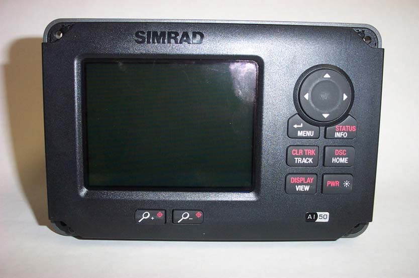
GL7AI50
Oct 02, 2008Class B AIS transponder
Equipment Class
AIS - Automatic Identification Systems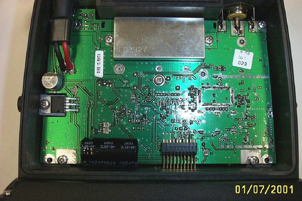
GL7RT63
Jul 08, 2001RT63 VHF marine Radiotelephone with DSC interface
Equipment Class
TNB - Licensed Non-Broadcast Station TransmitterGL7RD68
Dec 18, 2000VHF Marine radiotelephone inc class 'D' DSC controller
Equipment Class
TNB - Licensed Non-Broadcast Station Transmitter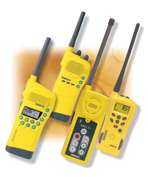
GL7AXIS50
Feb 16, 2000VHF handheld
Equipment Class
GHH - Part 80 VHF Hand Held Transmitter (GMDSS)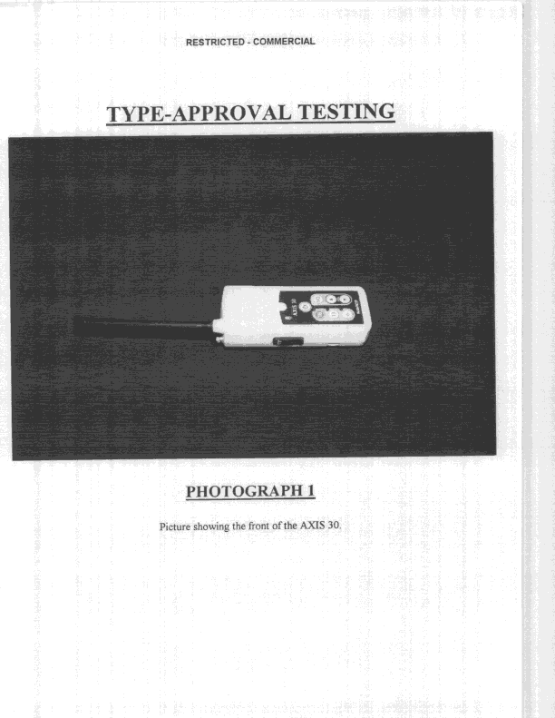
GL7AXIS30
Nov 08, 1998GVH - Part 80 VHF Transmitter (GMDSS)
Equipment Class
GVH - Part 80 VHF Transmitter (GMDSS)