HE7DTGRFID Tag For Asset Protection System
Xmark Corporation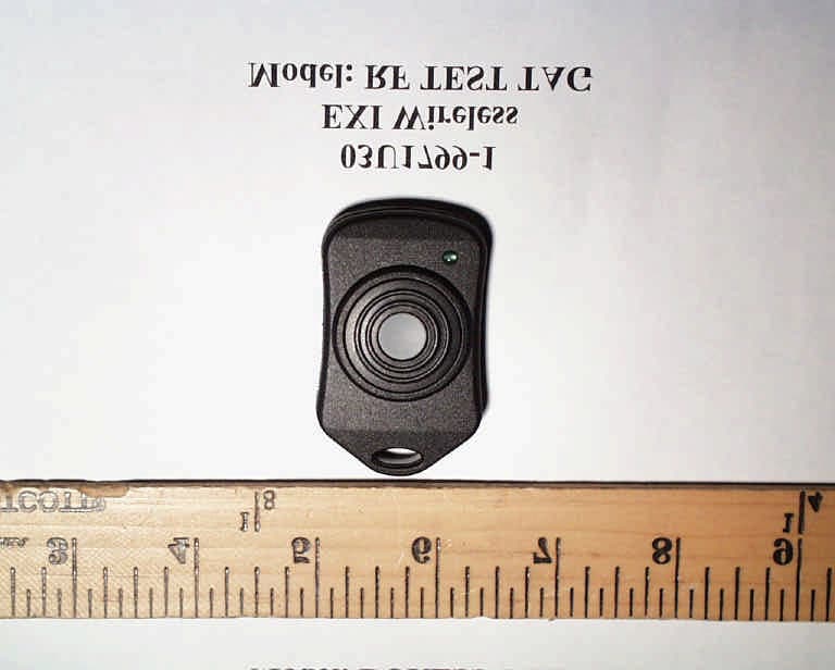
Click to zoom
Application Details
- Equipment Class
- DSC - Part 15 Security/Remote Control Transmitter
- Date of Grant
- Apr 16, 2003
- Application Purpose
- Original Equipment
- Date of Application
- Apr 16, 2003
- Equipment Note
- RFID Tag For Asset Protection System
- Frequency Range
- 433.92000000 - 433.92000000
- Company
- Xmark Corporation
- Country
- Canada
Documents & Files
Document Text
Text extracted from the exhibit documents filed with the FCC. Open a document above to read the original.
Users Manual
Duress Tag Duress Tag USER GUIDEUSER GUIDE 983-000021-000R1.00 11 OVERVIEWOVERVIEW In an eXI Asset Protection system (Halo, Roam Alert e.g.) user tags are identified by the system when they enter a field of protection. Additionally, some tags will automatically transmit a coded message that the system will recognize as either an alarm message or a location message. With the Duress Tag, the user may manually initiate an alarm message to an eXI Asset Protection System. The protection system may be customized to provide appropriate indications to the system administrators, depending on the encoded tag identification. • A lanyard is supplied with the tag for convenience. 22 FUNCTIONALFUNCTIONAL • To send a distress message press the push button. • The green LED indicator will flash at the rate of 3 times per second to indicate message transmission. • While the pushbutton is held on, the distress message is transmitted once per second. • On release of the button, the message will continue to be transmitted once a second for 5 second and then will be transmitted at the rate of once every 12 seconds for one minute and the LED will flash once per message transmission. • The Duress Tag remains inactive unless entered into a field of protection or the Duress Message is initiated by the user. eXI systems are designed to assist staff in providing a high degree of safety for people and therefore should only be used as a component of a comprehensive security program of policies, procedures, and processes. As with every security system, eXI highly recommends regular system operational checks to verify functional integrity. © 2002 eXI Wireless Systems Inc. All rights reserved. eXI, eLink, and all respective logos are either trademarks or registered trademarks or eXI Wireless Systems Inc. Specifications subject to change without notice. eXI Wireless Systems Inc. · 100-13551 Commerce Parkway, Richmond, BC Canada V6V 2L1 · Phone (800) 667-9689 · Fax (604) 207-7760 · www.exi.com This device complies with Part 15 of the FCC Rules. Operation is subject to the following two conditions: (1) This device may not cause harmful interference, and (2) This device must accept any interference received, including interference that may cause undesired operation.
Users Manual
RF Test Tag RF Test Tag USER GUIDEUSER GUIDE 983-000022-000R1.00 11 OVERVIEWOVERVIEW The RF Test Tag is a tool for the use of installers and administrators in the analysis and optimization of eXI Asset Protection systems. The device emulates a system RFID tag when entered into a field of protection and completes the TIF communication with the system. The user may manually initiate an RF test message, which is transmitted in TLM format. The test message signal level is significantly lower than the system tags, providing a valuable aid for the adjustment of the system receiver sensitivities and the analysis of localized performance. A lanyard is supplied with the tag for convenience. 22 FUNCTIONALFUNCTIONAL • To initate the test message press the push button. • The green LED indicator will flash with each transmission. • While the pushbutton is held on, the test message is transmitted three times a second. • On release of the button, transmission of the RF Test Message is terminated and the tag reverts to normal tag operation. • The RF Test Tag remains inactive unless entered into a field of protection or the Test Message is initiated by the user. eXI systems are designed to assist staff in providing a high degree of safety for people and therefore should only be used as a component of a comprehensive security program of policies, procedures, and processes. As with every security system, eXI highly recommends regular system operational checks to verify functional integrity. © 2002 eXI Wireless Systems Inc. All rights reserved. eXI, eLink, and all respective logos are either trademarks or registered trademarks or eXI Wireless Systems Inc. Specifications subject to change without notice. eXI Wireless Systems Inc. · 100-13551 Commerce Parkway, Richmond, BC Canada V6V 2L1 · Phone (800) 667-9689 · Fax (604) 207-7760 · www.exi.com This device complies with Part 15 of the FCC Rules. Operation is subject to the following two conditions: (1) This device may not cause harmful interference, and (2) This device must accept any interference received, including interference that may cause undesired operation.
Cover Letter(s)
From: Claire Hoque Sent: Tuesday, April 01, 2003 3:22 PM To: Mike Kuo Cc: Anne Liang; Thu Chan Subject: RE: EXI WIRELESS SYSTEMS INC., FCC ID:HE7DTG, AN03T2684 Hi Mike, Here are the answers for EXI. Question #1: Based upon the theory of operation description, this device can not comply 15.231(b) requirement. This transmitter is transmitting TIC/TLM message which is not allowed under 15.231(b) requirement. Section 15.231(e) technical requirement shall be used. Please revise the test report with the correct limits for 15.231(e). ANSWER: Pls see the attached revised test report. Question #2: Please address section 15.231(e) requirement on the duration of each transmitter and silent period requirement. Please address the Duress Tag and Test Tag together. ANSWER: Pls see the attached sheet provided by Thu. Question #3: User manual does not contain information required under section 15.21 of FCC rules. ( Duress Tag and Test tag ) ANSWER: EXI has confirmed that they would add the statement “Changes or modifications not expressly approved by eXi could void the user’s authority to operate the equipment” in their system and product user manuals. Question #4: The EUT description for this device is described as RFID Door access Tags which does not agree the intended usage as described in the user manual. Please make necessary changes. ANSWER: We have updated the EUT description, pls see the attached revised report. Thanks, Claire
ID Label/Location Info
PROPOSED FCC ID LABEL AND LOCATION EXI WIRELESS SYSTEMS INC. This device complies with Part 15 of the FCC Rules. Operation is subject to the following two conditions: (1) this device may not cause harmful interference, and (2) this device must accept any interference received, including interference that may cause undesired operation. FCC ID: HE7DTG FCC ID LABEL LOCATION
Test Report
FCC PART 15 SUBPART C CERTIFICATION REPORT FOR 433.92 MHz RFID TAGS FOR ASSET PROTECTION SYSTEM MODEL: DURESS TAG, RF TEST TAG FCC ID NO: HE7DTG REPORT NO: 03U1799-1 ISSUE DATE: FEBUARY 21, 2003 Prepared for EXI WIRELESS SYSTEMS INC. SUITE 100, 13551 COMMERCE PARKWAY RICHMOND, BC CANADA Prepared by COMPLIANCE ENGINEERING SERVICES, INC. d.b.a. COMPLIANCE CERTIFICATION SERVICES 561F MONTEREY ROAD MORGAN HILL, CA 95037 USA TEL: (408) 463-0885 FAX: (408) 463-0888 REPORT NO: 03U1799-1 DATE: FEBUARY 21, 2003 EUT: 433.92 MHz RFID TAGS FOR ASSET PROTECTION SYSTEM FCC ID: HE7DTG COMPLIANCE CERTIFICATION SERVICES CCS DOCUMENT NO:CCSUP4020B 561F MONTEREY RD., MORGAN HILL, CA 95037, USA TEL:(408)463-0885 FAX:(408)463-0888 This report shall not be reproduced except in full, without the written approval of CCS. This document may be altered or revised by Compliance Certification Services personnel only, and shall be noted in the revision section of the document. TABLE OF CONTENTS PAGE 1. VERIFICATION OF COMPLIANCE........................................................................................3 2. PRODUCT DESCRIPTION........................................................................................................3 3. TEST FACILITY.........................................................................................................................4 4. MEASUREMENT STANDARDS..............................................................................................4 5. TEST METHODOLOGY............................................................................................................4 6. MEASUREMENT EQUIPMENT USED....................................................................................4 7. POWERLINE RFI LIMIT...........................................................................................................5 8. RADIATED EMISSION LIMITS...............................................................................................5 9. SYSTEM TEST CONFIGURATION.........................................................................................6 10. TEST PROCEDURE.................................................................................................................7 11. EQUIPMENT MODIFICATIONS............................................................................................8 12. TEST RESULT..........................................................................................................................9 12.1 MAXIMUM MODULATION PERCENTAGE (M%)...........................................................9 12.2 THE EMISSIONS BANDWIDTH..........................................................................................9 TEST DATA • Maximum Modulation Percentage Plot • Emission Bandwidth Plot • Radiated Emission Worksheet for Peak Measurement • Radiated Emission Worksheet for Average Measurement ATTACHMENT • EUT Photographs • Proposed FCC ID Label • Schematics & Block Diagram • User Manual REPORT NO: 03U1799-1 DATE: FEBUARY 21, 2003 EUT: 433.92 MHz RFID TAGS FOR ASSET PROTECTION SYSTEM FCC ID: HE7DTG Page 3 of 22 COMPLIANCE CERTIFICATION SERVICES CCS DOCUMENT NO:CCSUP4020B 561F MONTEREY RD., MORGAN HILL, CA 95037, USA TEL:(408)463-0885 FAX:(408)463-0888 This report shall not be reproduced except in full, without the written approval of CCS. This document may be altered or revised by Compliance Certification Services personnel only, and shall be noted in the revision section of the document. 1. VERIFICATION OF COMPLIANCE COMPANY NAME : EXI WIRELESS SYSTEMS INC. SUITE 100, 13551 COMMERCE PARKWAY RICHMOND BC, CANADA EUT DESCRIPTION : 433.92 MHz RFID TAGS FOR ASSET PROTECTION SYSTEM MODEL NO : DURESSS TAG, RF TEST TAG FCC ID : HE7DTG DATE TESTED : 2-21-2003 REPORT NUMBER : 03U1799-1 TYPE OF EQUIPMENT RF TAGS EQUIPMENT TYPE 433.92MHz TRANSCEIVERS MEASUREMENT PROCEDURE ANSI C63.4 / 2001 LIMIT TYPE CERTIFICATION FCC RULE CFR 47, PART 15 The above equipment was tested by Compliance Certification Services for compliance with the requirements set forth in the FCC CFR 47, PART 15. The results of testing in this report apply to the product/system which was tested only. Other similar equipment will not necessarily produce the same results due to production tolerance and measurement uncertainties. Warning : This document reports conditions under which testing was conducted and results of tests performed. This document may not be altered or revised in any way unless done so by Compliance Certification Services and all revisions are duly noted in the revisions section. Any alteration of this document not carried out by Compliance Certification will constitute fraud and shall nullify the document. Tested By: CHIN PANG EMC TECHNICIAN COMPLIANCE CERTIFICATION SERVICES Approved & Released By: THU CHAN EMC SUPERVISOR COMPLIANCE CERTIFICATION SERVICES REPORT NO: 03U1799-1 DATE: FEBUARY 21, 2003 EUT: 433.92 MHz RFID TAGS FOR ASSET PROTECTION SYSTEM FCC ID: HE7DTG Page 4 of 22 COMPLIANCE CERTIFICATION SERVICES CCS DOCUMENT NO:CCSUP4020B 561F MONTEREY RD., MORGAN HILL, CA 95037, USA TEL:(408)463-0885 FAX:(408)463-0888 This report shall not be reproduced except in full, without the written approval of CCS. This document may be altered or revised by Compliance Certification Services personnel only, and shall be noted in the revision section of the document. 2. PRODUCT DESCRIPTION Fundamental Frequency 433.92 MHz Power Source 12V Battery Transmitting Time Periodic < 5 seconds Associated Receiver NA Manufacturer EXI Wireless Systems Inc. 3. TEST FACILITY The 3/10/30 meter open area test site and conducted measurement facility used to collect the radiated data is located at 561F Monterey Road, Morgan Hill, California, U.S.A. A detailed description of the test facility was submitted to the Commission on May 27,1994. 4. MEASUREMENT STANDARD The site is constructed and calibrated in conformance with the requirements of ANSI C63.4/2001. 5. TEST METHODOLOGY For an inten…
Text truncated - open the document above for the full version.
Test Setup Photos
REPORT NO: 03U1799-1 DATE: FEBUARY 21, 2003 EUT: 433.92 MHz RFID DOOR ACCESS TAG FCC ID: HE7DTG Page 6 of 22 COMPLIANCE CERTIFICATION SERVICES CCS DOCUMENT NO:CCSUP4020B 561F MONTEREY RD., MORGAN HILL, CA 95037, USA TEL:(408)463-0885 FAX:(408)463-0888 This report shall not be reproduced except in full, without the written approval of CCS. This document may be altered or revised by Compliance Certification Services personnel only, and shall be noted in the revision section of the document. 9. SYSTEM TEST CONFIGURATION Use a block of foam and combined it with EUT wrapping rubber band around it. This way it can test X.Y, and Z axis. To activate continuous transmission, place a small plastic block between rubber band and EUT push button. Radiated Open Site Test Set-up X-Axis Y-Axis Z-Axis
Contact Information
Applicant
Chris Bisaillion(Senior RF Designer)
Test Firm
Compliance Certification Services IncSteve Cheng
Technical Specifications
| # | Rule Parts | Frequency Range | Power Output |
|---|---|---|---|
| 1 | 15.231,15.231(e) | 433.92 MHz - 433.92 MHz | - |
Other Applications from Xmark Corporation
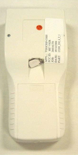
HE7VH2R
Oct 18, 2006VERICHIP H2 READER
Equipment Class
DXX - Part 15 Low Power Communication Device Transmitter
HE7VACR
May 21, 2006VERIGUARRD ACCESS CONTROL READER
Equipment Class
DXX - Part 15 Low Power Communication Device Transmitter
HE7PCR
Apr 06, 2005Receiver
Equipment Class
CYY - Communications Receiver used w/Pt 15 Transmitter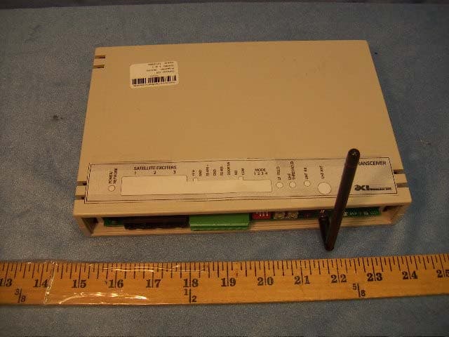
HE7EAC
Feb 07, 2005Transceiver
Equipment Class
DCD - Part 15 Low Power Transmitter Below 1705 kHz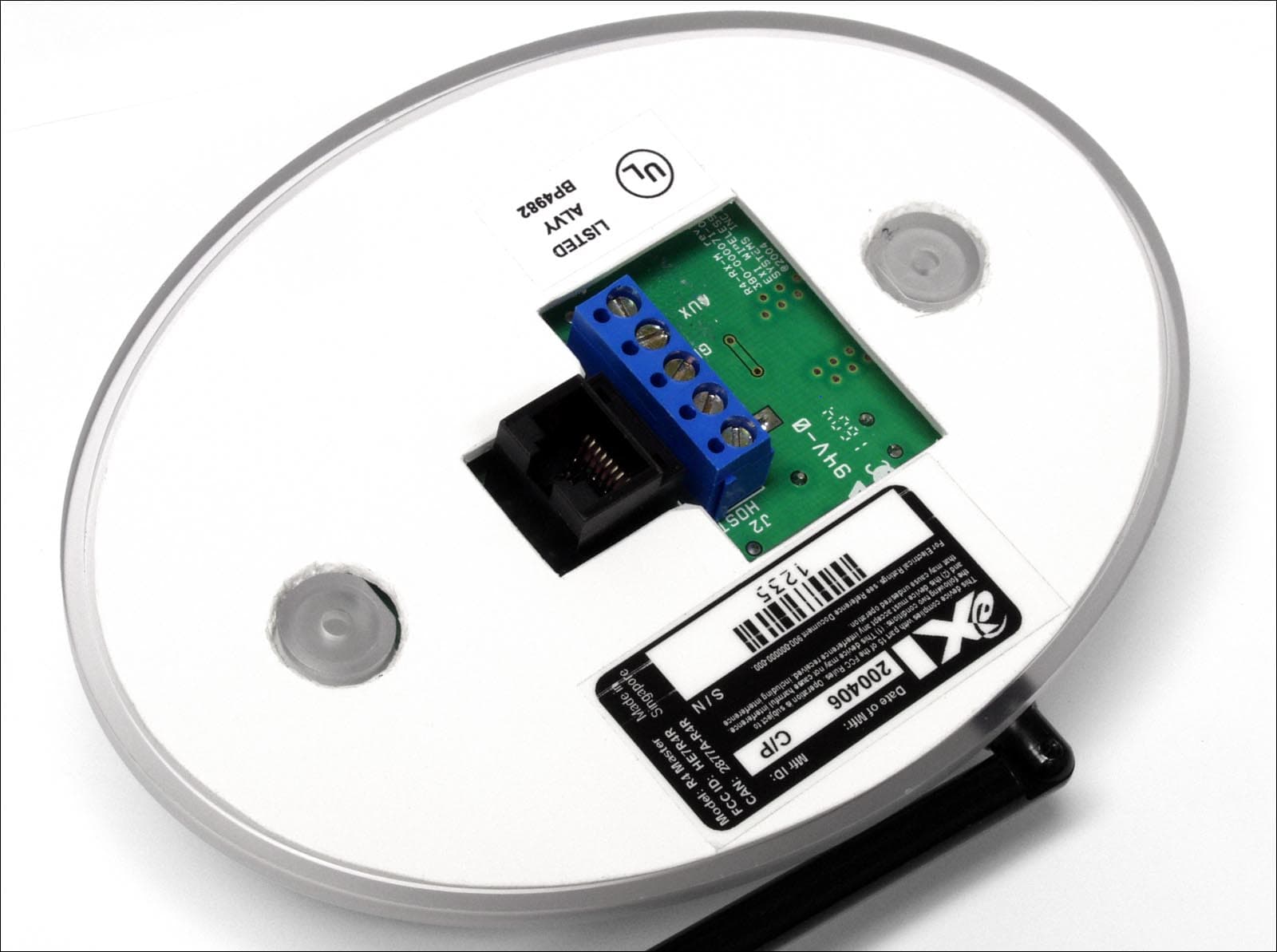
HE7R4R
Oct 13, 2004Communications Receiver
Equipment Class
CYY - Communications Receiver used w/Pt 15 Transmitter