HE7PCRReceiver
Xmark Corporation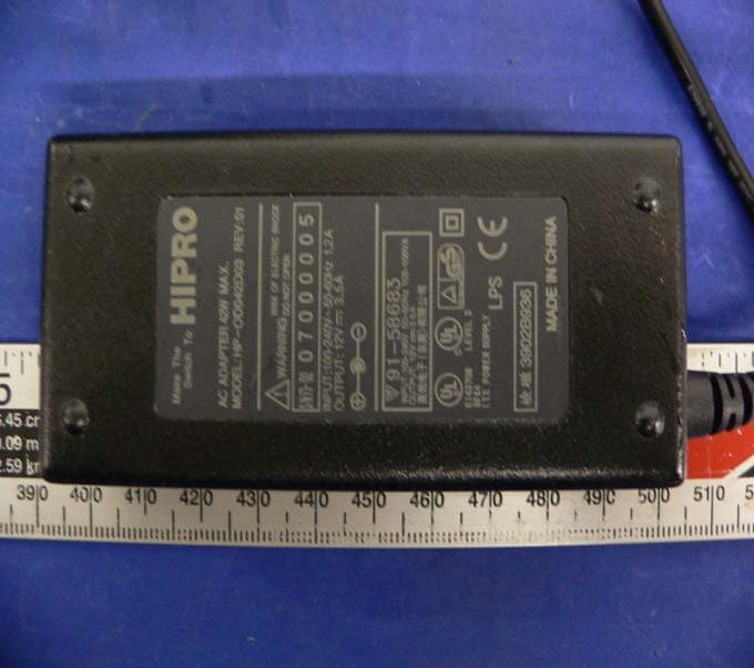
Click to zoom
Application Details
- Equipment Class
- CYY - Communications Receiver used w/Pt 15 Transmitter
- Date of Grant
- Apr 06, 2005
- Application Purpose
- Original Equipment
- Date of Application
- Apr 06, 2005
- Equipment Note
- Receiver
- Frequency Range
- 433.92000000 - 433.92000000
- Company
- Xmark Corporation
- Country
- Canada
Documents & Files
Document Text
Text extracted from the exhibit documents filed with the FCC. Open a document above to read the original.
Users Manual
eLink PCMCIA Card: User Guide 980-000039-000R1.00 1 FUNCTION The purpose of this product is to provide a truly mobile e-Link tag reader device that detects and displays information giving relative proximity of the Tags it is receiving messages from. It is designed to plug into the PCMCIA card slot of a Windows CE based off the shelf device running “eLink Mobile ReaderWare” (eMR) executable software. 2 INSTALLATION & POWER UP Insert the eLink PCMCIA Card (ePC) in the device (e.g. Hewlet Packard I-PAQ 5500 pocket PC) and power up the unit. Launch eMR (eLink Mobile ReaderWare) from the keypboard or touchscreen. The ePC will not power up until initiated through eMR. The antenna position is not critical but will generally give best reception if extended away from the host device. There are no user adjustments required for the receiver. 3 OPERATION ‘Start’ Screen Refer to eAC HUB network installation instructions for network cabling requirements. • At the start screen, select either SHOW ALL TAGS or SEARCH FOR TAGS. • eMR tries to establish communication to the “eLink PCMCIA Card”. If the card is detected the software enters Active Mode and proceeds to the selected screen. • If the card is not detected, the software returns to Passive Mode and shows an error message. • While in Active Mode, if no user input is detected for more then 5 minutes and “Power Saver” option is selected in “PCMCIA Settings” screen, the Active Mode reverts to Passive Mode automatically EAC Transceiver: Installation Guide 981-000046-000R1.00 ‘Show All Tags’ Screen • All acquired Tags are shown (Tag ID numbers) on the screen with corresponding bar graph, which indicates strength of received RF signal (RSSI). (The screen may be scrolled.) • The bar-graph length is proportional to received RSSI value. • On a top of the tag list there is a slider which allows user to set Receiver RF sensitivity. “FAR” means high sensitivity (low RSSI threshold) and “CLOSE” means low sensitivity (high RSSI threshold). By default this sensitivity is set to maximum (“FAR” setting). This sensitivity sets RSSI threshold, and only messages with RSSI higher than threshold are shown on the screen. • Refer to eMR application User Guide for additional operations on received and displayed tag information. ‘Search For Tag’ Screen • This screen is used to search for a specific Tag that was either selected from list of Tags in some other screen or has been entered in this screen. • On screen keyboard is available in this screen that enables user to enter Tag ID number. Tag ID must start with letters A-F and must be 6 characters in total (e.g. B12345). • On the top of the screen there is a slider which allows user to set RF sensitivity. By default this sensitivity is set to maximum. • When Tag is detected bar-graph is shown, indicating received signal strength. (Bar-graph is updated with every location message received.) ‘PCMCIA Card Settings’ Screen • Hardware RF sensitivity can be set in this screen. There are 4 available levels of receiver sensitivity.. • “Power Saver” radio button is available. When this button is selected (default setting), and no user activity is detected for 5 minutes, Active Mode will be interrupted, PCMCIA card powered down and eMR will enter Passive Mode. FCC Regulations This device complies with Part 15 of the FCC Rules. Operation is subject to the following two conditions: (1) This device may not cause harmful interference, and (2) This device must accept any interference received, including interference that may cause undesired operation. This equipment has been tested and found to comply with the limits for Class B Digital Device, pursuant to Part 15 of the FCC Rules. These limits are designed to provide reasonable protection against harmful interference in a residential installation. This equipment generates and can radiate radio frequency energy and, if not installed and used in accordance with the instructions, may cause harmful interference to radio communications. However, there is no guarantee that interference will not occur in a particular installation. If this equipment does cause harmful interference to radio or television reception, which can be determined by turning the equipment off and on, the user is encouraged to try to correct the interference by one or more of the following measures. • Reorient or relocate the receiving antenna • Increase the separation between the equipment and Receiver • Connect the equipment into an outlet on a circuit different from that to which the Receiver is connected • Consult the dealer or an experienced radio/TV technician for help Any changes or modifications not expressly approved by the party responsible for compliance could void the user’s authority to operate the equipment.
External Photos
EXHIBIT B - EUT EXTERNAL PHOTOGRAPHS Chassis 1 - Front View Chassis 1 – Rear View Chassis 2 - Front View Chassis 2 - Rear View EUT - Port View Power Supply
ID Label/Location Info
§15.19, §15.21, §15.27, §15.105 - FCC PRODUCT LABELING AND WARNING STATEMENT Proposed FCC Label Format Proposed Label Location on EUT Rear View of EUT/Proposed FCC Label Location
Internal Photos
EXHIBIT B - EUT INTERNAL PHOTOGRAPHS EUT – Component View EUT – Solder View
Test Report
Note: This test report is specially limited to the use of the above client company and the product model only. It may not be duplicated without prior written consent of Bay Area Compliance Laboratory Corporation. This report must not be used by the client to claim product Endorsement by NVLAP or any agency of the U.S. Government. FCC PART 15 CLASS B EMI MEASUREMENT AND TEST REPORT For EXI Wireless Systems Inc. 100-13551 Commerce Parkway Richmond, BC, V6V 2L1, Canada FCC ID: HE7PCR 2005-04-01 This Report Concerns: Original Report Equipment Type: 433.92 MHz Receiver with PCMCIA Interface Test Engineer: Jerry Wang / Report No.: R0503171 Test Date: 2005-03-21 Reviewed By: Hang Tan/ Prepared By: Bay Area Compliance Laboratory Corporation (BACL) 230 Commercial Street Sunnyvale, CA 94085 Tel: (408) 732-9162 Fax: (408) 732-9164 EXI Wireless Systems Inc. FCC ID: HE7PCR Report # R0503171RPT Page 2 of 15 FCC 15 Subpart B Report TABLE OF CONTENTS GENERAL INFORMATION.......................................................................................................................................3 PRODUCT DESCRIPTION FOR EQUIPMENT UNDER TEST (EUT) ....................................................................................3 OBJECTIVE...................................................................................................................................................................3 RELATED SUBMITTAL(S)/GRANT(S).............................................................................................................................3 TEST METHODOLOGY..................................................................................................................................................3 TEST FACILITY.............................................................................................................................................................3 SYSTEM TEST CONFIGURATION ..........................................................................................................................5 JUSTIFICATION.............................................................................................................................................................5 EUT EXERCISE SOFTWARE..........................................................................................................................................5 SPECIAL ACCESSORIES.................................................................................................................................................5 SCHEMATICS / BLOCK DIAGRAM.................................................................................................................................5 EQUIPMENT MODIFICATIONS.......................................................................................................................................5 HOST SYSTEM CONFIGURATION LIST AND DETAILS....................................................................................................5 LOCAL SUPPORT EQUIPMENT LIST AND DETAILS........................................................................................................5 PRINTED CIRCUIT BOARDS IN EUT ..............................................................................................................................5 POWER SUPPLY AND LINE FILTERS..............................................................................................................................5 INTERFACE PORTS AND CABLING.................................................................................................................................6 CONFIGURATION OF TEST SYSTEM..............................................................................................................................7 SUMMARY OF TEST REPORT.................................................................................................................................8 §15.107 - CONDUCTED EMISSIONS ........................................................................................................................9 MEASUREMENT UNCERTAINTY....................................................................................................................................9 EUT SETUP..................................................................................................................................................................9 RECEIVER SETUP..........................................................................................................................................................9 TEST EQUIPMENT LIST AND DETAILS...........................................................................................................................9 TEST PROCEDURE........................................................................................................................................................9 ENVIRONMENTAL CONDITIONS..................................................................................................................................10 TEST RESULTS SUMMARY..........................................................................................................................................10 CONDUCTED EMISSIONS TEST DATA.........................................................................................................................10 PLOTS OF CONDUCTED EMISSION..............................................................................................................................10 §15.109 - RADIATED EMISSIONS...........................................................................................................................13 MEASUREMENT UNCERTAINTY..................................................................................................................................13 EUT SETUP....................................................................................................................................…
Text truncated - open the document above for the full version.
Test Setup Photos
EXHIBIT A - TEST SETUP PHOTOGRAPHS Conducted Emission – Front View Conducted Emission – Rear View Radiated Emission Front View Radiated Emission Rear View
Contact Information
Applicant
Chris Bisaillion(Senior RF Designer)
Test Firm
Bay Area Compliance LaboratoryJohn Chan
Technical Specifications
| # | Rule Parts | Frequency Range | Power Output |
|---|---|---|---|
| 1 | 15B | 433.92 MHz - 433.92 MHz | - |
Other Applications from Xmark Corporation
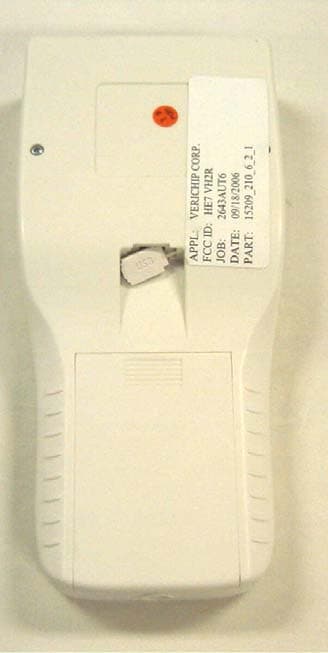
HE7VH2R
Oct 18, 2006VERICHIP H2 READER
Equipment Class
DXX - Part 15 Low Power Communication Device Transmitter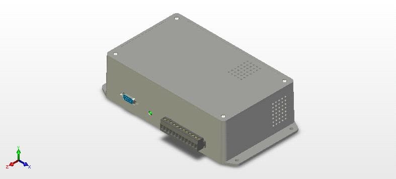
HE7VACR
May 21, 2006VERIGUARRD ACCESS CONTROL READER
Equipment Class
DXX - Part 15 Low Power Communication Device Transmitter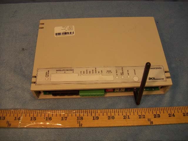
HE7EAC
Feb 07, 2005Transceiver
Equipment Class
DCD - Part 15 Low Power Transmitter Below 1705 kHz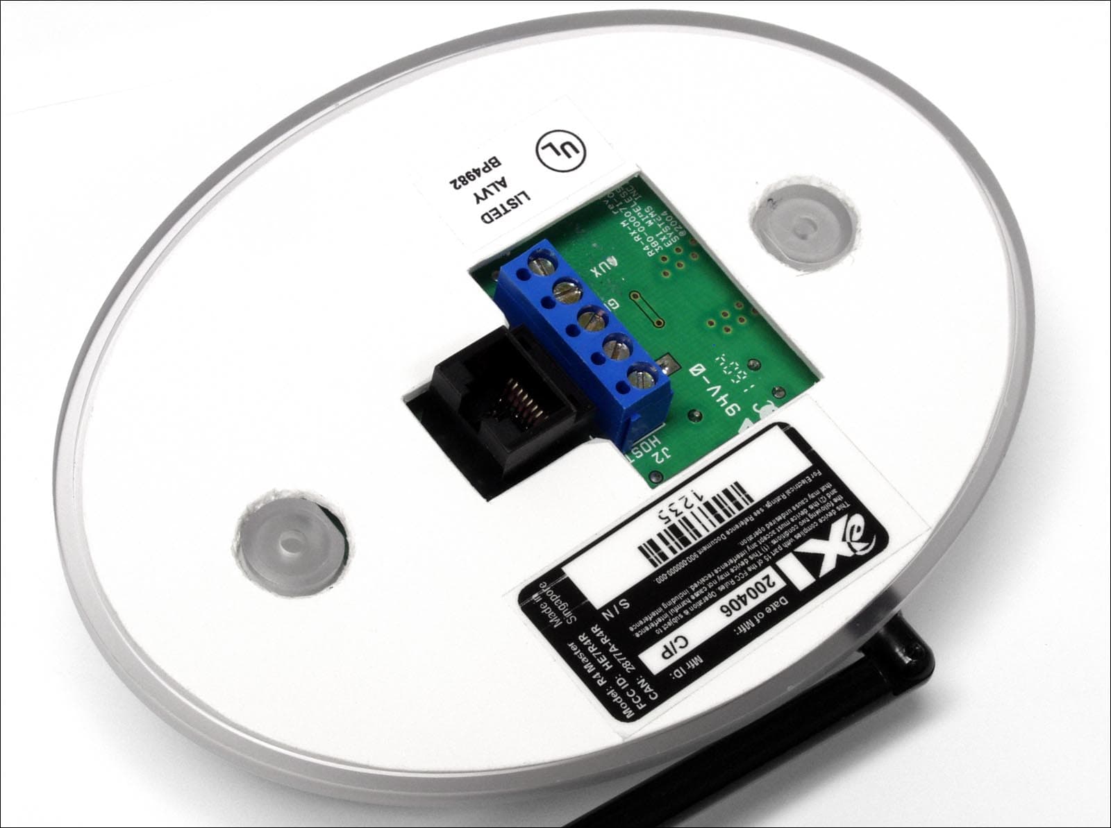
HE7R4R
Oct 13, 2004Communications Receiver
Equipment Class
CYY - Communications Receiver used w/Pt 15 Transmitter
HE7MT2
Sep 29, 2004RFID Tag Reader
Equipment Class
DSR - Part 15 Remote Control/Security Device Transceiver