HE7EACTransceiver
Xmark Corporation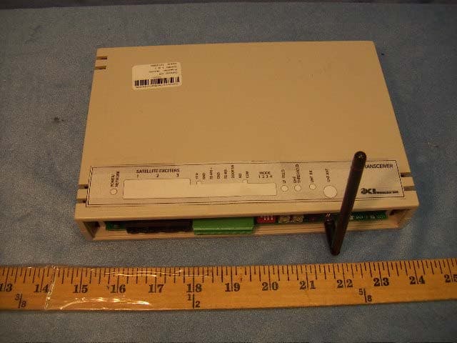
Click to zoom
Application Details
- Equipment Class
- DCD - Part 15 Low Power Transmitter Below 1705 kHz
- Date of Grant
- Feb 07, 2005
- Application Purpose
- Original Equipment
- Date of Application
- Feb 07, 2005
- Equipment Note
- Transceiver
- Frequency Range
- 0.30700000 - 0.30700000
- Company
- Xmark Corporation
- Country
- Canada
Documents & Files
Document Text
Text extracted from the exhibit documents filed with the FCC. Open a document above to read the original.
Users Manual
EAC Transceiver: Installation Guide 981-000046-000R1.05 1 CONNECTIONS NO USER DEFINED RELAY CONTACTS GND LISTED CAT 5E FROM DOOR SWIT C COM 3A/30VDC RESITIVE EAC TRANSCEIVER 24VDC 300MA 250VA PWR LIMITED SELV SUPPLY NOTE: 307.2 kHz EXCITER INDUCTORS MOUNTED ON PC BOARD GND 1 2 3 4 5 6 7 8 RS485 + 433.92 MHz RECEIVE ANTENNA RS485 - DOOR SW RS485 NETWORK +Vin eAC System components are designed to meet the requirements for Class 2 circuits operating from a non-hazardous secondary power source limited to 240 VA. Cabling materials must be selected for the installation environment in accordance with the applicable jurisdictional codes. 2 INSTALLATION MOUNTING INSTRUCTIONS The Controller chassis may be horizontally or vertically mounted on a wall, ceiling, or shelf as long as the front face panel is easily accessible. The RX antenna should be positioned on a vertical plane for maximum performance. The detection field radiates from two internal orthogonal ferrite cored inductors. The field must fill the area in front of the door all the way to the floor so that no Tag can reach the door without being detected. SATELLITE EXTENSION 1 2 3 NOT USED ON THIS PRODUCT EAC Transceiver: Installation Guide 981-000046-000R1.00 3 TUNING & ADJUSTMENT An eXI RF Test Tag is used for adjustment of the Receiver Threshold and LF Field Strength NETWORK STATUS Refer to eAC HUB network installation instructions for network cabling requirements. NETWORK STATUS INDICATOR LED CONDITION OFF No power to Receiver Solid GREEN Power supplied; Network normal Flashing GREEN Power supplied: Network Communication Failure RECEIVER SENSITIVITY The UHF Threshold control may be adjusted to increase or reduce the range of detection of the UHF transmission of the Tags. Threshold adjustment removes some of the background noise, and reduces interference from Tags not within the field of the Transceiver. Initially decrease the threshold (CCW) until the UHF RX indicator flashes occasionally. This will establish a threshold sensitivity to background noise at the door site. Using the RF Test Tag in the keyed mode, reduce the receiver sensitivity (increase threshold CW) until the RX indicator becomes intermittent at 25 to 30 feet. Reduce the threshold slightly and walk the tag around the area of coverage to check for consistent UHF reception. LF FIELD ADJUSTMENT Adjust the LF Field for a compromise between maximum desired tag detection range and the potential to excite tags in adjacent rooms or floors. Note that the LF field tends to be omni-directional. Starting with the field adjustment at maximum (full CW), walk the RF Test Tag around the area of desired protection. Reduce the field until inconsistent tag identification occurs in parts of the coverage. (The UHF Threshold adjustment should be increased to check that the eLink is not being limited by the UHF link.) Increase the field strength in small increments until consistent detection results within the desired area of detection. FCC Regulations This device complies with Part 15 of the FCC Rules. Operation is subject to the following two conditions: (1) This device may not cause harmful interference, and (2) This device must accept any interference received, including interference that may cause undesired operation. This equipment has been tested and found to comply with the limits for Class B Digital Device, pursuant to Part 15 of the FCC Rules. These limits are designed to provide reasonable protection against harmful interference in a residential installation. This equipment generates and can radiate radio frequency energy and, if not installed and used in accordance with the instructions, may cause harmful interference to radio communications. However, there is no guarantee that interference will not occur in a particular installation. If this equipment does cause harmful interference to radio or television reception, which can be determined by turning the equipment off and on, the user is encouraged to try to correct the interference by one or more of the following measures. • Reorient or relocate the receiving antenna • Increase the separation between the equipment and Receiver • Connect the equipment into an outlet on a circuit different from that to which the Receiver is connected • Consult the dealer or an experienced radio/TV technician for help Any changes or modifications not expressly approved by the party responsible for compliance could void the user’s authority to operate the equipment. EAC Transceiver: Installation Guide 981-000046-000R1.00 eXI Wireless Systems Model No.: eAC Transceiver CANADA: 2877A-EAC FCC ID: HE7EAC Made in Singapore CAUTION – RISK OF EXPLOSION IF LITHIUM BATTERY IS REPLACED WITH AN INCORRECT TYPE. DISPOSE OF USED BATTERY ACCORDING TO THE INSTRUCTIONS OF THE MANUFACTURER. eXI systems are designed to assist staff in providing a high degree of safety for people and therefore should only be used as a component of a comprehensive security program of policies, procedures, and processes. As with every security system, eXI highly recommends regular system operational checks to verify functional integrity. © 2002 eXI Wireless Systems Inc. All rights reserved. eXI, eLink, and all respective logos are either trademarks or registered trademarks or eXI Wireless Systems Inc. Specifications subject to change without notice. eXI Wireless Systems Inc. · 100-13551 Commerce Parkway, Richmond, BC Canada V6V 2L1 · Phone (800) 667-9689 · Fax (604) 207-7760 · www.exi.com
Cover Letter(s)
01/31/2005 09:32 604-207-7765 EXI WIRELESS PAGE 02/02 I : ~I I WI~i"ss.'SyrnM~ I January 31,2005 Federal Comm\mications Commission Authorization and Evaluation Division Equipment Authorization Branch 7435 Oakland Mills Road Columbia, MD 21046 Gentlemen: In reference to the application under FCC ill: HE7EAC, and pursuant to Sections O.457(d)(I)(ii) and 0,459 of the Commission's Rules, the Applicant hereby requests confidential treatment of the accompanying information as outlined below: Schematics Block Diagram Theory of Operation. These documents contain detailed system and equipment description and related information about the product that EX! Wireless Systems Inc, considers to be proprietary, confidential, and a custom design and, otherwise, would not release to the general public- Since this design is a basis from which future technological products .will evolve, EX! Wireless Systems Inc. considers that this information would be of benefit to its Competitors, and that disclosure of the information would be of benefit to its conwetitors, and that disclosure of the information in these documents would give competitors an unfair advantage in the market. S;tf7~ , Bruce R. Barlow, NPI Engineer I . I EX! WIfeless Systems Inc. I Suite 1 00 3551 COmmerce pa~ Richmond. BC Canada V6V 2Ll Phone (604) 207-7760 1-800-667-9689 I IFax (604) 207-7765 I e-mail: "[email protected] www,exl,com I
ID Label/Location Info
PROPOSED FCC ID LABEL AND LOCATION EXI WIRELESS SYSTEMS INC. This device complies with Part 15 of the FCC Rules. Operation is subject to the following two conditions: (1) this device may not cause harmful interference, and (2) this device must accept any interference received, including interference that may cause undesired operation. FCC ID: HE7EAC FCC ID LABEL LOCATION
Test Report
RADIO FREQUENCY EMISSIONS TEST REPORT FOR TRANSCEIVER MODEL NUMBER: EAC TRANSCEIVER FCC ID: HE7EAC REPORT NUMBER: 04U3150-1 ISSUE DATE: JANUARY 28, 2005 Prepared for EXI WIRELESS SYSTEMS INC. SUITE 100, 13551 COMMERCE PARKWAY RICHMOND, BC, CANADA Prepared by COMPLIANCE ENGINEERING SERVICES, INC. d.b.a. COMPLIANCE CERTIFICATION SERVICES 561F MONTEREY ROAD, MORGAN HILL, CA 95037, USA TEL: (408) 463-0885 FAX: (408) 463-0888 REPORT NO: 04U3150-1 ATE: JANUARY 28, 2005 EUT: TRANSCEIVER FCC ID: HE7EAC Page 2 of 25 COMPLIANCE CERTIFICATION SERVICES DOCUMENT NO: CCSUP4031A 561F MONTEREY ROAD, MORGAN HILL, CA 95037 USA TEL: (408) 463-0885 FAX: (408) 463-0888 This report shall not be reproduced except in full, without the written approval of CCS. Revision History Rev. Revisions Revised By REPORT NO: 04U3150-1 ATE: JANUARY 28, 2005 EUT: TRANSCEIVER FCC ID: HE7EAC Page 3 of 25 COMPLIANCE CERTIFICATION SERVICES DOCUMENT NO: CCSUP4031A 561F MONTEREY ROAD, MORGAN HILL, CA 95037 USA TEL: (408) 463-0885 FAX: (408) 463-0888 This report shall not be reproduced except in full, without the written approval of CCS. TABLE OF CONTENTS 1. ATTESTATION OF TEST RESULTS............................................................................................. 4 2. TEST METHODOLOGY .................................................................................................................. 5 3. FACILITIES AND ACCREDITATION .......................................................................................... 5 4. CALIBRATION AND UNCERTAINTY.......................................................................................... 5 4.1. MEASURING INSTRUMENT CALIBRATION ............................................................................. 5 4.2. MEASUREMENT UNCERTAINTY ............................................................................................... 5 5. EQUIPMENT UNDER TEST............................................................................................................6 5.1. DESCRIPTION OF EUT ..............................................................................................................6 5.2. DETAILS OF TESTED SYSTEM .................................................................................................. 6 6. TEST AND MEASUREMENT EQUIPMENT ................................................................................ 8 7. EUT MODIFICATION ...................................................................................................................... 8 8. APPLICABLE LIMITS AND TEST RESULTS ............................................................................. 9 8.1. TX RADIATED EMISSIONS BELOW 30 MHZ ............................................................................ 9 8.2. DUTY CYCLE ............................................................................................................................. 11 8.3. 99% BANDWIDTH ..................................................................................................................... 14 8.4. RADIATED EMISSIONS RELATIVE TO CLASS B LIMITS ...................................................... 16 9. SETUP PHOTOS .............................................................................................................................. 24 REPORT NO: 04U3150-1 ATE: JANUARY 28, 2005 EUT: TRANSCEIVER FCC ID: HE7EAC Page 4 of 25 COMPLIANCE CERTIFICATION SERVICES DOCUMENT NO: CCSUP4031A 561F MONTEREY ROAD, MORGAN HILL, CA 95037 USA TEL: (408) 463-0885 FAX: (408) 463-0888 This report shall not be reproduced except in full, without the written approval of CCS. 1. ATTESTATION OF TEST RESULTS COMPANY NAME: EXI WIRELESS SYSTEMS INC. SUITE 100, 13551 COMMERCE PARKWAY RICHMOND BC, CANADA EUT DESCRIPTION: TRANSCEIVER MODEL: EAC TRANSCEIVER SERIAL NUMBER: 710010 DATE TESTED: DECEMBER 13-14, 2004 and JANURAY 28, 2005 APPLICABLE STANDARDS STANDARD TEST RESULTS FCC PART 15 SUBPART B NON-COMPLIANCE NOTED Compliance Certification Services, Inc. tested the above equipment in accordance with the requirements set forth in the above standards. The test results show that the equipment tested is capable of demonstrating compliance with the requirements as documented in this report. Note: The results documented in this report apply only to the tested sample, under the conditions and modes of operation as described herein. This document may not be altered or revised in any way unless done so by Compliance Certification Services and all revisions are duly noted in the revisions section. Any alteration of this document not carried out by Compliance Certification Services will constitute fraud and shall nullify the document. No part of this report may be used to claim product certification, approval, or endorsement by NVLAP, NIST, or any government agency. Approved & Released For CCS By: Tested By: THU CHAN CHIN PANG EMC SUPERVISOR EMC TECHNICIAN COMPLIANCE CERTIFICATION SERVICES COMPLIANCE CERTIFICATION SERVICES REPORT NO: 04U3150-1 ATE: JANUARY 28, 2005 EUT: TRANSCEIVER FCC ID: HE7EAC Page 5 of 25 COMPLIANCE CERTIFICATION SERVICES DOCUMENT NO: CCSUP4031A 561F MONTEREY ROAD, MORGAN HILL, CA 95037 USA TEL: (408) 463-0885 FAX: (408) 463-0888 This report shall not be reproduced except in full, without the written approval of CCS. 2. TEST METHODOLOGY The tests documented in this report were performed in accordance with ANSI C63.4-2003. 3. FACILITIES AND ACCREDITATION The test sites and measurement facilities used to collect data are located at 561F Monterey Road, Morgan Hill, California, USA. The sites are constructed in conformance with the requirements of ANSI C63.4, ANSI C63.7 and CISPR Publication 22. All receiving equipment conforms to CISPR Publication 16-1, “Radio Interference Measuring Apparatus and Measurement Methods.” CCS is accredited by NVLAP, Laboratory Code 200065-0. The full scope of accreditation can be viewed at http://www.ccsemc.com . 4. CALIBRATION AND UNCERTAINTY 4.1. MEASURING I…
Text truncated - open the document above for the full version.
Test Setup Photos
REPORT NO: 04U3150-1 DATE: JANUARY 28, 2005 EUT: TRANSCEIVER FCC ID: HE7EAC Page 24 of 25 COMPLIANCE CERTIFICATION SERVICES DOCUMENT NO: CCSUP4031A 561F MONTEREY ROAD, MORGAN HILL, CA 95037 USA TEL: (408) 463-0885 FAX: (408) 463-0888 This report shall not be reproduced except in full, without the written approval of CCS. 9. SETUP PHOTOS RADIATED EMISSION RADIATED EMISSIONS (FRONT) REPORT NO: 04U3150-1 DATE: JANUARY 28, 2005 EUT: TRANSCEIVER FCC ID: HE7EAC Page 25 of 25 COMPLIANCE CERTIFICATION SERVICES DOCUMENT NO: CCSUP4031A 561F MONTEREY ROAD, MORGAN HILL, CA 95037 USA TEL: (408) 463-0885 FAX: (408) 463-0888 This report shall not be reproduced except in full, without the written approval of CCS. END OF REPORT RADIATED EMISSIONS (BACK)
Contact Information
Applicant
Chris Bisaillion(Senior RF Designer)
Test Firm
Compliance Certification Services IncSteve Cheng
Technical Specifications
| # | Rule Parts | Frequency Range | Power Output |
|---|---|---|---|
| 1 | 15C | 0.307 MHz - 0.307 MHz | - |
Other Applications from Xmark Corporation
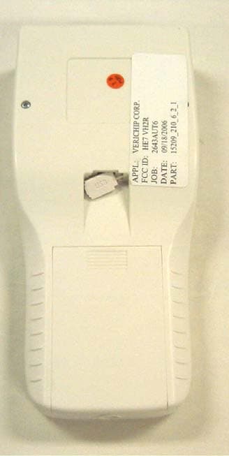
HE7VH2R
Oct 18, 2006VERICHIP H2 READER
Equipment Class
DXX - Part 15 Low Power Communication Device Transmitter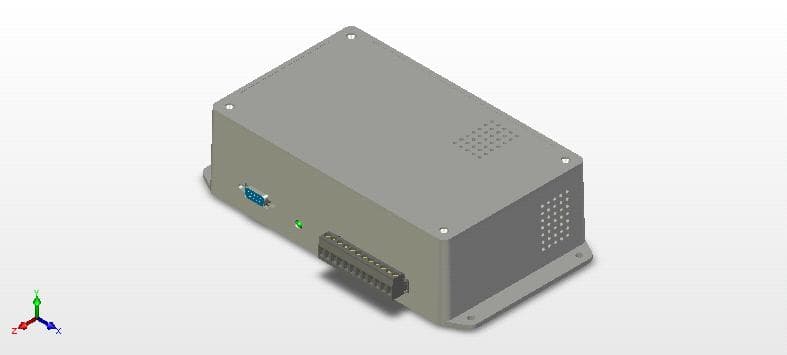
HE7VACR
May 21, 2006VERIGUARRD ACCESS CONTROL READER
Equipment Class
DXX - Part 15 Low Power Communication Device Transmitter
HE7PCR
Apr 06, 2005Receiver
Equipment Class
CYY - Communications Receiver used w/Pt 15 Transmitter
HE7R4R
Oct 13, 2004Communications Receiver
Equipment Class
CYY - Communications Receiver used w/Pt 15 Transmitter
HE7MT2
Sep 29, 2004RFID Tag Reader
Equipment Class
DSR - Part 15 Remote Control/Security Device Transceiver