HE7R4RCommunications Receiver
Xmark Corporation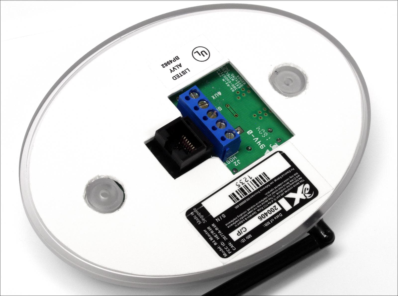
Click to zoom
Application Details
- Equipment Class
- CYY - Communications Receiver used w/Pt 15 Transmitter
- Date of Grant
- Oct 13, 2004
- Application Purpose
- Original Equipment
- Date of Application
- Oct 13, 2004
- Equipment Note
- Communications Receiver
- Frequency Range
- 433.92000000 - 433.92000000
- Company
- Xmark Corporation
- Country
- Canada
Documents & Files
Document Text
Text extracted from the exhibit documents filed with the FCC. Open a document above to read the original.
Users Manual
eLink Area Receiver (Master and Satellite) INSTALLATION GUIDE 1 CONTENTS The eLink Area Receiver extends the eLink system’s capability to monitor and receive Tag messages such as tamper alarm that may occur in areas not within the detection zone of a Controller. The eLink Area Receiver bundle contains: • 1 eLink Area Receiver Master • 4 eLink Area Receiver Satellites 2 COMPONENT CONNECTIONS Master Receiver Satellite Receiver 5-pin connector RJ-45 connector Two identical RJ-45 connectors Aux. Output* GND RS+ RS- V+ *Activated in Alarm condition eLINK AREA RECEIVER INSTALLATION GUIDE 981-000045-000R1.06 3 INSTALLATION MOUNTING INSTRUCTIONS Each Master Receiver supports up to seven Satellite Receivers. The Satellites are connected in a daisy chain via the RJ-45 connectors. eLINK AREA RECEIVER INSTALLATION GUIDE 981-000045-000R1.06 ⇒ Place the Receiver in the approximate location for final use. ⇒ The Receiver is mounted onto a standard single gang electrical box. ⇒ Connect the power supply and system network cables to the 5 pin connector on the Master receiver (the 12VDC to 24 VDC supply should be OFF while connecting). Note: Each Receiver has a unique electronic serial number that is associated with the location of the Receiver in the building. The computer indicates the correct location of an event on the floor plans by using this serial number association. Therefore, ensure that the correct Receiver is installed at the corresponding location. ⇒ If the wall is dielectric (plaster), the antenna can be left parallel to the wall, but should point away from the receiver. ⇒ If the receiver is installed on a conductive surface (metal wall, or wall with metal mesh inside), the antenna should be swiveled away from mounting surface. eLINK AREA RECEIVER INSTALLATION GUIDE 981-000045-000R1.06 4 OPERATION AND INDICATORS STATUS LED INDICATOR Type of Receiver Action LED Indicator Power applied, no Network Slow, dim flashing Power applied, Network OK Continuous dim glow Master (yellow LED) RF Event (e.g. Tamper Alarm) Bright flash followed by previous state Power applied, no Network Slow, dim flashing Power applied, Network OK Continuous dim glow RF Event (e.g. Tamper Alarm) Bright flash followed by previous state Satellite (green LED) Communication rate with host has not yet been detected (host has not confirmed) Bright solid light ACTIVE OUTPUT The eLink Area Master Receiver is equipped with an active DC output that produces a voltage equal to applied to the receiver and current- limited at 125 mA DC in the case of tamper alarm. The output can drive a relay coil or other similar devices. The output is activated for 5 seconds after each alarm event. AUTOMATIC SENSITIVITY (THRESHOLD) ADJUSTMENT eLink Area Receivers are equipped with a circuit that automatically adjusts the detection level threshold according to current level of RF noise at installation site. This circuit assumes that the receiver will provide maximum coverage possible in a given environment. Abnormally high levels of external interference will not prevent the receiver’s operation, but will decrease the detection range. Status LED indicator Top view of eLink Area Receiver eLINK AREA RECEIVER INSTALLATION GUIDE 981-000045-000R1.06 TESTING THE RF COVERAGE The eLink Area Receiver can be used together with an RF test tag to test the RF coverage. The Receiver is equipped with an audible piezo beeper, which will respond to valid Test Transponder messages only. When the transmit button is pressed on the RF Test Tag, the Receiver will provide audible feedback as it receives the message from the RF Test Tag. By placing the Receiver in each proposed HALO Receiver location, the effective coverage around the receiver may be confirmed prior to establishing the system RF coverage map, and device location plan. The unit can also help an engineer identify RF-shielded areas within the facility. While holding the RF Test Tag button continuously, move throughout the area to be covered by the receiver. You should hear an audible tone from the Receiver when the RF Test Tag message is received. Where the tone interval becomes irregular, tag communication may be unreliable at that location. This may be because you are near the perimeter of the nominal reception range, or there may be building infrastructure affecting tag reception from that location. Please see the Technician Test Kit User Guide for more information about the test kit available and complete instructions on testing the RF coverage. FCC Regulations This device complies with Part 15 of the FCC Rules. Operation is subject to the following two conditions: (1) This device may not cause harmful interference, and (2) This device must accept any interference received, including interference that may cause undesired operation. Changes or modifications not expressly approved by EXI Wireless could void the user’s authority to operate the equipment. This equipment has been tested and found to comply with the limits for Class B Digital Device, pursuant to Part 15 of the FCC Rules. These limits are designed to provide reasonable protection against harmful interference in a residential installation. This equipment generates and can radiate radio frequency energy and, if not installed and used in accordance with the instructions, may cause harmful interference to radio communications. However, there is no guarantee that interference will not occur in a particular installation. If this equipment does cause harmful interference to radio or television reception, which can be determined by turning the equipment off and on, the user is encouraged to try to correct the interference by one or more of the following measures. • Reorient or relocate the receiving antenna • Increase the separation between the equipment and receiver • Connect the equipment into an outlet on a circuit different from that to which the receiver is connected • Consult the dealer or an experienced radio/TV technician for help eXI systems are de…
Text truncated - open the document above for the full version.
Cover Letter(s)
Model Differences Regarding the difference/similarities of the two versions (Master and Satellite), this is also described in the Theory document -- see section 2.2. The only difference between the two is that the Satellite uses a micro controller with a smaller memory, has only one RS485 transceiver, does not provide an auxilliary output, and uses two Modular jacks (Master has one Modular jack and a 5 position wire terminal strip).
ID Label/Location Info
FCC/IC SN Label Placement
ID Label/Location Info
1235
ID Label/Location Info
1235
Test Report
Master: FCC Part15 SubpartB.doc - Date: April 5, 2004 Test Report: 4R08262.1 Issue 2 Applicant: eXI Wireless Systems Inc. Suite 100.13551 Commerce Parkway Richmond, BC Canada V6V 2L1 Equipment Under Test: eLink Master Receiver Model Number: R4 Master In Accordance With: FCC 47 CFR Part 15, Subpart B Verification Tested By: Nemko Canada Inc. 303 River Road, R.R. 5 Ottawa, Ontario K1V 1H2 Authorized By: Daniel Hynes, EMC Specialist Date: 13 October 2004 Total Number of Pages: 16 Reference Standard: FCC 47 CFR Part 15, Subpart B Test Report No: 4R08262.1 Issue 2 Nemko Canada Inc., Ottawa, Ontario Canada Equipment (EUT): eLink Master Receiver Page 2 of 16 Table of Contents Measurement Uncertainty ........................................................................................................................................... 3 Lab Environmental Conditions ................................................................................................................................... 3 Declaration.................................................................................................................................................................. 4 Summary of Test Results ............................................................................................................................................ 5 Engineering Considerations ........................................................................................................................................ 7 General Information Regarding the Equipment Under Test (EUT) ........................................................................... 8 Equipment Configuration ........................................................................................................................................... 9 Radiated Disturbance ................................................................................................................................................ 11 Conducted Disturbance at Mains Port ...................................................................................................................... 13 Nemko Canada Inc. authorizes the applicant to reproduce this report provided it is reproduced in its entirety and for use by the company’s employees only. Any use which a third party makes of this report, or any reliance on or decisions to be made based on it, are the responsibility of such third parties. Nemko Canada Inc. accepts no responsibility for damages, if any suffered by any third party as a result of decisions made or actions based on this report. This report shall not be reproduced except in full without the written approval of the testing laboratory. Reference Standard: FCC 47 CFR Part 15, Subpart B Test Report No: 4R08262.1 Issue 2 Nemko Canada Inc., Ottawa, Ontario Canada Equipment (EUT): eLink Master Receiver Page 3 of 16 Measurement Uncertainty Accuracy of Measurement Measurement uncertainty was calculated using the methods described in CISPR 16-4 Specification for radio disturbance and immunity measuring apparatus and methods – Part 4: Uncertainty in EMC measurements and Nemko Canada Inc. procedure EMC/MUC/001 Uncertainty in EMC Measurements. Test Specific Measurement Uncertainty Measurement Test Specification Ulab 9kHz – 150kHz 4.0dB Conducted disturbance 150kHz – 30MHz 3.6dB 30MHz – 200MHz Horizontal polarization 4.7dB 200MHz – 1000MHz Horizontal polarization 4.7dB 30MHz – 200MHz Vertical polarization 4.9dB Radiated disturbance 200MHz – 1000MHz Vertical polarization 4.9dB Lab Environmental Conditions Lab Conditions Ambient Temperature: 15°C to 35°C, Relative Humidity: 30% to 60%, Atmospheric Pressure: 86kPa (860mbar) to 106kPa (1 060mbar) Reference Standard: FCC 47 CFR Part 15, Subpart B Test Report No: 4R08262.1 Issue 2 Nemko Canada Inc., Ottawa, Ontario Canada Equipment (EUT): eLink Master Receiver Page 4 of 16 Declaration Product Name: eLink Master Receiver Model No: R4 Master Trademark: Serial No: N/A Name of Applicant: eXI Wireless systems Inc Name of Manufacturer: eXI Wireless systems Inc TEST RESULT Nemko Canada Inc., Ottawa, Ontario Canada PASS FAIL In the configuration tested, the EUT complied with the requirements of: FCC 47 CFR Part 15, Subpart B for Class B. Digital Devices. X Note: See Summary of Test Results and Engineering Considerations for full details. Tested by: 13 October 2004 Signature Date Phil Taffinder, EMC & Telecom Specialist Reviewed by: 13 October 2004 Signature Date Daniel Hynes, EMC Specialist Nemko Canada Inc., a testing laboratory, is accredited by the Standards Council of Canada. The tests included in this report are within the scope of this accreditation. Reference Standard: FCC 47 CFR Part 15, Subpart B Test Report No: 4R08262.1 Issue 2 Nemko Canada Inc., Ottawa, Ontario Canada Equipment (EUT): eLink Master Receiver Page 5 of 16 Summary of Test Results General These tests were conducted on a sample of the equipment for the purpose of demonstrating compliance with FCC Part 15, Subpart B for Digital Devices. These tests were conducted using measurement procedures of ANSI C63.4-2001. The equipment was tested for conducted emissions from 0.15MHz to 30MHz using a 50 microhenry line impedance stabilization network (L.I.S.N.) as described in ANSI C63.4-2001. Peripheral equipment was also operated through a 50 microhenry L.I.S.N. Limits For Conducted Disturbance At The Mains Ports: Paragraph No. 15.107 for Class A Limits dB(μV) Frequency Range MHz Quasi-Peak Average Result (Pass/Fail) 0.15 to 0.50 79 66 0.50 to 30 73 60 N/A Limits For Conducted Disturbance At The Mains Ports: Paragraph No. 15.107 for Class B Limits dB(μV) Frequency Range MHz Quasi-Peak Average Result (Pass/Fail) 0.15 to 0.50 66 to 56 56 to 46 0.5 to 5 56 46 5 to 30 60 50 Pass Notes 1. The lower limit shall apply at the transition frequency. 2. The limit decreases linearly with the logarithm of the frequency in the range 0.15 to 0.50MHz. Reference Standard: FCC 47 CFR Pa…
Text truncated - open the document above for the full version.
Test Setup Photos
Reference Standard: FCC 47 CFR Part 15, Subpart B Test Report No: 4R08262.1 Issue 2 Nemko Canada Inc., Ottawa, Ontario Canada Equipment (EUT): eLink Master Receiver Page 12 of 16 Radiated Disturbance, continued Enclosure Port, Radiated Electromagnetic Field Emissions Setup Photos Front View Rear View Reference Standard: FCC 47 CFR Part 15, Subpart B Test Report No: 4R08262.1 Issue 2 Nemko Canada Inc., Ottawa, Ontario Canada Equipment (EUT): eLink Master Receiver Page 14 of 16 Conducted Disturbance at Mains, continued Conducted Disturbance at Mains Setup Photos
Contact Information
Applicant
Chris Bisaillion(Senior RF Designer)
Test Firm
Nemko Canada Inc. (Ottawa)Charles Neal
Technical Specifications
| # | Rule Parts | Frequency Range | Power Output |
|---|---|---|---|
| 1 | 15B | 433.92 MHz - 433.92 MHz | - |
Other Applications from Xmark Corporation
HE7VH2R
Oct 18, 2006VERICHIP H2 READER
Equipment Class
DXX - Part 15 Low Power Communication Device Transmitter
HE7VACR
May 21, 2006VERIGUARRD ACCESS CONTROL READER
Equipment Class
DXX - Part 15 Low Power Communication Device Transmitter
HE7PCR
Apr 06, 2005Receiver
Equipment Class
CYY - Communications Receiver used w/Pt 15 Transmitter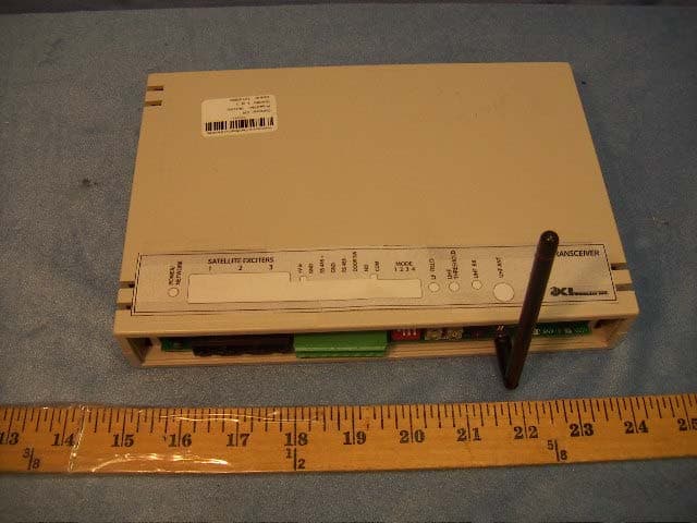
HE7EAC
Feb 07, 2005Transceiver
Equipment Class
DCD - Part 15 Low Power Transmitter Below 1705 kHz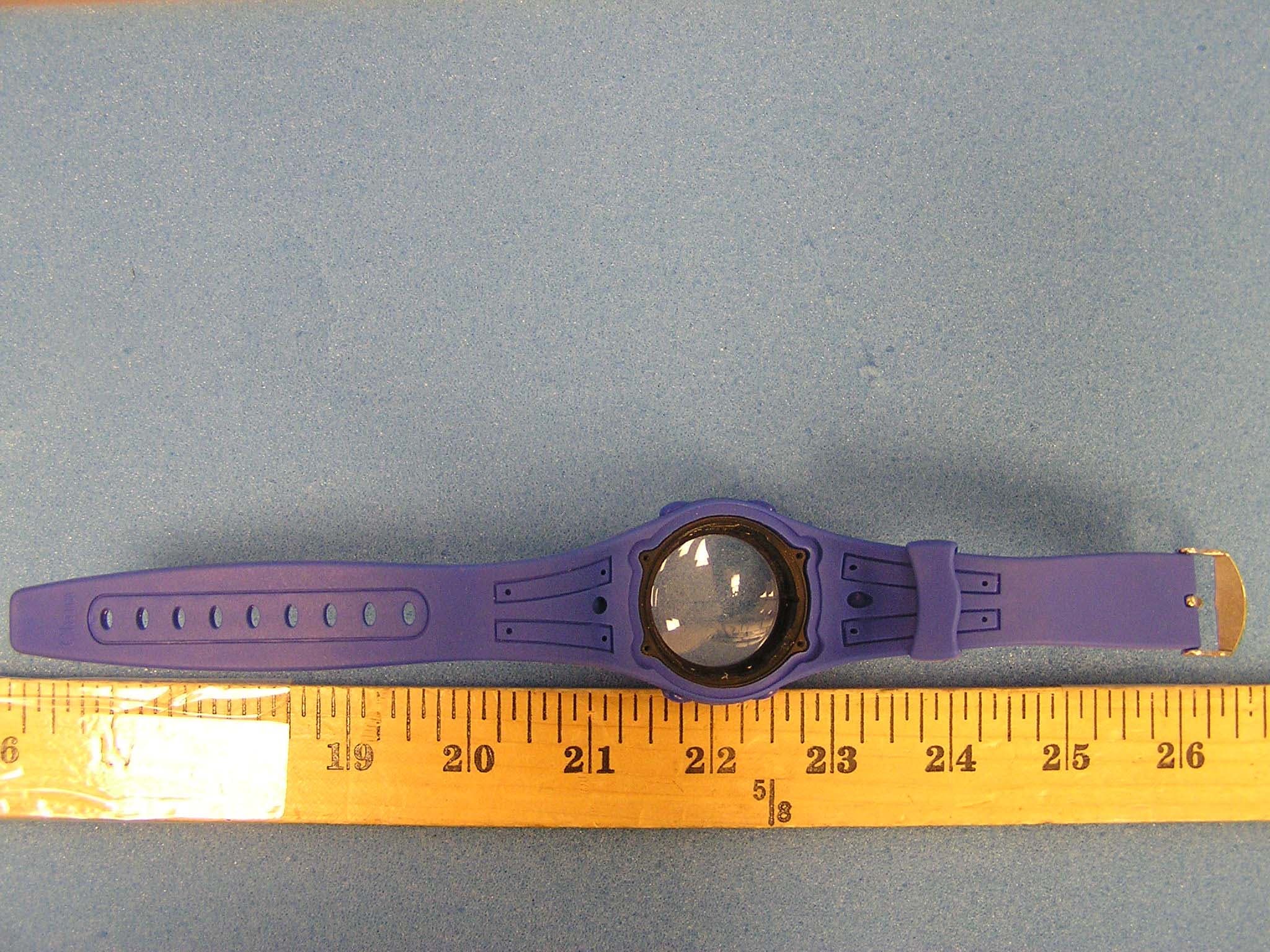
HE7MT2
Sep 29, 2004RFID Tag Reader
Equipment Class
DSR - Part 15 Remote Control/Security Device Transceiver