HE7R2RSUPERHETERODYNE RECEIVER
Xmark CorporationApplication Details
- Equipment Class
- CYY - Communications Receiver used w/Pt 15 Transmitter
- Date of Grant
- Nov 28, 1999
- Application Purpose
- Original Equipment
- Date of Application
- Nov 15, 1999
- Equipment Note
- SUPERHETERODYNE RECEIVER
- Frequency Range
- 434.00000000 - 434.00000000
- Company
- Xmark Corporation
- Country
- Canada
Documents & Files
Document Text
Text extracted from the exhibit documents filed with the FCC. Open a document above to read the original.
Users Manual
“Halo” System Communication Protocol Revision 0.1 July 27, 1999 970-00002-000 “Halo” System: Communication Protocol970-00002-000 EXI Wireless Systems, ConfidentialPage 2 of 33July 27, 1999 Revisions VersionDateChanged byDescription 0.16/29/99Dalibor PokrajacInitial Release “Halo” System: Communication Protocol970-00002-000 EXI Wireless Systems, ConfidentialPage 3 of 33July 27, 1999 Approvals COO______________________________________Date:___________________ Engineering______________________________________Date:___________________ Manufacturing______________________________________Date:___________________ Quality______________________________________Date:___________________ Purchasing______________________________________Date:___________________ “Halo” System: Communication Protocol970-00002-000 EXI Wireless Systems, ConfidentialPage 4 of 33July 27, 1999 1.Document Purpose..........................................................................................................6 2.Introduction.....................................................................................................................7 3.System Architecture.........................................................................................................8 3.1.Host..............................................................................................................................8 3.2.Data Gathering and Control Nodes...........................................................................8 3.2.1.Controller......................................................................................................................................9 3.2.2.Elevator.........................................................................................................................................9 3.2.3.Receiver.........................................................................................................................................9 3.3.Sensors.........................................................................................................................9 3.4.Communication...........................................................................................................9 3.4.1.RF Communication....................................................................................................................10 3.4.2.Weigand Communication...........................................................................................................10 3.4.3.Control Lines Communication..................................................................................................10 3.4.4.EIA-485 Communication...........................................................................................................10 4.RF Communication Protocol.......................................................................................11 4.1.Tag in the Field (TIF Alarm)....................................................................................11 4.1.1.Field of coverage........................................................................................................................11 4.1.2.Bit By Bit Interrogation..............................................................................................................12 4.1.3.Respond Command.....................................................................................................................13 4.1.4.Reset Command..........................................................................................................................14 4.2.Tag Initiated Communication (TIC alarm).............................................................14 4.2.1.Message format...........................................................................................................................15 ID number format........................................................................................................................................16 5.Weigand Communication Protocol.............................................................................17 5.1.General......................................................................................................................17 5.2.Weigand Messages....................................................................................................17 5.2.1.Parity Bits (Even and Odd).........................................................................................................18 5.2.2.Control Code...............................................................................................................................19 5.2.2.1.Normal................................................................................................................................19 5.2.2.2.Bypassed..............................................................................................................................19 5.2.2.3.TIF Alarm............................................................................................................................19 5.2.2.4.Loiter...................................................................................................................................19 5.2.2.5.Host Alarm ON...................................................................................................................20 5.2.2.6.Unlock Request ON...........................................................................................................20 5.2.2.7.TIC Alarm...........................................................................................................................20 5.2.2.8.Test Mode...........................................................................................................................20 5.2.2.9.Pin Number Entry...............................................................................................................20 5.2.2.10.Event (Door Open).....................................................…
Text truncated - open the document above for the full version.
Users Manual
© Copyright 1999, EXI Wireless Systems Inc. All rights reserved. Installation Manual for Controllers and Receivers June, 1999 EXI HALO Installation ManualRev 2.0 EXI Wireless Systems Inc.Page 2June, 1999 Revisions DateChanged byDescription 6/9/99Zahir AbjiFirst Release 6/17/99Zahir AbjiSystem Wiring section added and Halo Wiring Diagram corrected Any changes or modifications not expressly approved by the manufacturer could void the user’s authority to oper- ate the equipment. NOTICE: This equipment has been tested and found to comply with the limits of a class B digital device, pursuant to Part 15 of the FCC rules. These limits are designed to provide reasonable protection against harmful interference in a residential installation. This equipment generates, uses and can radiate radio frequency energy and, if not installed and used in accordance with the instructions, may cause harmful interference to radio communications. However, there is no guarantee that interference will not occur in a particular installation. If this equipment does cause harmful inter- ference to radio or television reception, which can be determined by turning the equipment off and on, the user is en- couraged to try and correct the interference by one or more of the following measures. (1) Reorient or locate the re- ceiving antenna. (2) Increase separation between the equipment and the receiver. (3) Connect the equipment into an outlet on a circuit different from that to which the receiver is connected. (4) Consult the dealer or an experienced radio/TV technician for help. NOTICE: Operation is subject to the following two conditions: (1) This device may not cause interference, and (2) This device must accept any interference, including interference that may cause undesired operation of the device. EXI HALO Installation ManualRev 2.0 EXI Wireless Systems Inc.Page 3June, 1999 LIMITED WARRANTY EXI Electronic Systems a division of Diversity Products Ltd. (collectively, “EXI”) hereby warrants the prod- uct(s) accompanying this limited warranty (the “Product(s)”) to be free of defects in materials and workmanship for a period of two years (excluding any batteries that may be added to or used in conjunction with the Prod- ucts(s)) from the date of delivery of the original purchase of the Product(s) subject to the limiting conditions set forth below, provided that EXI has received notification of such defects no later than 30 days after expiration of the applicable warranty period and provided further that EXI has received a fully completed registration card (below) within 30 days from the date of original purchase of the Product(s). The responsibility of EXI under this warranty is and shall be limited to repairing or replacing the Product(s) or any part thereof determined by EXI in its sole discretion to be defective in workmanship or material. The installation of the Product(s) shall be deemed as acceptance by the original purchaser and any subsequent purchaser of the Product(s) (collectively the “Purchaser”) of the terms set out in this limited warranty including the following further limiting conditions: (a)EXI shall not be responsible for any repair or replacement of any Product(s) which has been found, upon inspection, to have been subjected to abuse, misuse or negligence, or any damage attributable to accident, light- ning, power surge, brown-out, leaking, damaged or inoperative batteries or to have been installed, altered or repaired contrary to factory designated procedures without the prior written consent of EXI; (b)It is understood, and the Purchaser agrees further to so inform any user of the Product(s) that the Product(s) is not, nor can it be, infallible in the detection of wandering patients, the prevention of infant abduction, the pre- vention of theft of assets or any other contemplated use of the Product(s). The Purchaser will warn all users and acknowledges on it’s own behalf that it has read and understands the above-mentioned limitations of the Product(s). The Purchaser further acknowledges that the Product(s) are solely intended to provide an addi- tional safeguard in notifying staff and accordingly do not guarantee the prevention of wandering patients or the attempted abduction of an infant or the theft of assets; (c)It is further agreed by the Purchaser that the Purchaser has received no additional promises or statements of fact from EXI or its agents relative to the Product(s) upon which the Purchaser might have relied in purchasing the Product(s); (d)The warranty set out above excludes and is in lieu of all other express or implied warranties, conditions or obligations, and no person is authorized to give any further representation or warranty or assume any further obligation on behalf of EXI. Although the Purchaser may have other rights, as they may vary from State to State or Province to Province, where it is legally possible to do so any statutory warranty is hereby expressly ex- cluded. The warranty is subject to the domestic laws of the Province of Manitoba, Canada and the Purchaser agrees to attorn to the jurisdiction of the courts of competent jurisdiction in the Province of Manitoba; and (e)EXI shall not be liable for any damages, whether direct or, indirect, incidental, consequential or arising out of contact or tort with the sole exception of the warranty set out above and any rights expressly created by appli- cable statute. THIS WARRANTY IS VALID ONLY IN THE USA AND CANADA EXI HALO Installation ManualRev 2.0 EXI Wireless Systems Inc.Page 4June, 1999 Table of Contents 1.INTRODUCTION..............................................................................................................................................5 1.1.INTENDED AUDIENCE...................................................................................................................................5 1.2.SYSTEM OPERATION......................................................................................…
Text truncated - open the document above for the full version.
Users Manual
© Copyright 1999, EXI Wireless Systems Inc. All rights reserved. EXI HALO User ManualHalo User Manual R4 EXI Wireless Systems Inc.Page 2 of 33June, 1999 User Manual Revision 4 June 1999 © Copyright 1999, EXI Wireless Systems Inc. All rights reserved. HALO is a trade mark of EXI Wireless Systems Inc. Windows and Windows 98 are trade marks of Microsoft Inc. EXI HALO User ManualHalo User Manual R4 EXI Wireless Systems Inc.Page 3 of 33June, 1999 Table of Contents P 1.LIMITED WARRANTY........................................................................................................................5 P 2.SYSTEM MAINTENANCE..................................................................................................................5 P 3.INTENDED AUDIENCE.......................................................................................................................6 P 4.SCOPE......................................................................................................................................................6 P 5.ABOUT HALO INFANT PROTECTION SYSTEM........................................................................7 P 6.ACCESS LEVELS..................................................................................................................................7 P 7.SYSTEM CONVENTIONS...................................................................................................................8 P 8.SYSTEM SUPPORT..............................................................................................................................8 1.SYSTEM INTRODUCTION.................................................................................................................9 1.1.SYSTEM COMPONENTS...........................................................................................................................9 1.2.TERMS USED IN THIS DOCUMENT............................................................................................................9 1.3.COMPUTER DISPLAY CONVENTIONS....................................................................................................10 2.USER LEVEL.......................................................................................................................................11 2.1.ADMITTING A PATIENT..........................................................................................................................11 2.2.DISCHARGING A PATIENT.....................................................................................................................14 2.3.SILENCING AND ACCEPTING ALARMS..................................................................................................16 3.SUPERVISOR LEVEL........................................................................................................................19 3.1.ACCESSING SUPERVISOR LEVEL...........................................................................................................19 3.2.EXITING SUPERVISOR LEVEL................................................................................................................20 4.ACTIVITY LOG MANAGEMENT....................................................................................................21 4.1.ACTIVITY LOGS.....................................................................................................................................21 4.2.NAVIGATING THE ACTIVITY LOG...........................................................................................................22 4.3.ADDING A SUPERVISOR ANNOTATION TO AN ALARM............................................................................22 4.4.BACKING UP ACTIVITY LOGS................................................................................................................23 5.MANAGING TAGS..............................................................................................................................24 5.1.TAGS.....................................................................................................................................................24 5.2.ADDING A NEW P-TAG TO THE SYSTEM................................................................................................25 5.3.DELETING A P-TAG FROM THE SYSTEM................................................................................................26 5.4.DISABLING A P-TAG.............................................................................................................................27 5.5.UNASSIGNING A P-TAG........................................................................................................................27 5.6.EDITING A P-TAG RECORD...................................................................................................................28 5.7.PRINTING..............................................................................................................................................28 6.MANAGING SYSTEM USERS..........................................................................................................29 6.1.ADDING A NEW USER TO THE SYSTEM..................................................................................................30 6.2.DELETING A USER FROM THE SYSTEM..................................................................................................31 6.3.DISABLING A SYSTEM USER..................................................................................................................31 6.4.EDITING A SYSTEM USER ACCESS..........................................................................................................31 7.SHUTTING AND RESTARTING THE SYSTEM...........................................................................32 7.1.SHUTTING DOWN..................................................................................................................................32 7.2.RESTARTING THE SYSTEM....…
Text truncated - open the document above for the full version.
Attestation Statements
Authority to Act as Agent to the FCC May 17, 2001 Federal Communications Commission 7435 Oakland Mills Road Columbia, MD 21046 USA Authority to Act as Agent to the Federal Communications Commission On our behalf, I appoint KTL Ottawa to act as agent in the preparation of this application for equipment authorization to the Federal Communications Commission. I certify that submitted Exhibits properly describe the device or system for which equipment authorization is sought. I also certify that each unit manufactured, imported or marketed, as defined in the Commission's regulations will have affixed to it a label identical to that submitted for approval with this application. Dated this 9th Day of November 1999 Agency agreement expiration date: 10 month Denis Beaudoin By : ........................................................... ......................................................... SignaturePrinted Title: Director of Engineering Telephone: (604) 207 7760 Applicant: EXI Wireless Systems Inc. Suite 100 13551 Commerce Parkway Richmond, BC Canada V6V 2L1 Phone (604) 207-7760 1-800-667-9689 Fax (604) 207-7765 e-mail: [email protected] www.exi.com
Cover Letter(s)
Re: Change of address. May 17, 2001 Federal Communications Commission 7435 Oakland Mills Road Columbia, MD 21046 USA As of May 1999 we have moved to a new address and our company name has changed. Please update your records. (Our grantee code is HE7) Thank you Old address and company name: Diversity Products Ltd. 495 Madison St. Winnipeg, Manitoba, Canada, R3J 1J2 New address and company name: EXI Wireless Systems Inc. Suite 100 13551 Commerce Parkway Richmond, British Columbia Canada V6V 2L1 Dated this 9th Day of November 1999 Denis Beaudoin By : ........................................................... ......................................................... SignaturePrinted Title: Director of Engineering Telephone: (604) 207 7760 Fax: (604) 207 7765 Suite 100 13551 Commerce Parkway Richmond, BC Canada V6V 2L1 Phone (604) 207-7760 1-800-667-9689 Fax (604) 207-7765 e-mail: [email protected] www.exi.com
Cover Letter(s)
November 17, 1999 Federal Communications Commission Equipment Authorization Branch 7435 Oakland Mills Road Columbia, Maryland 21046 USA Dear Sir/Madam:Our File Ref. 9R05172.1 FCC ID: HE7R2R Applicant: EXI Wireless Systems Inc. Equipment: Standalone Superheterodyne Receiver FCC Confirmation no.: EA95998 We have successfully electronically filed all the required documentation for an application for certification in accordance with FCC Part 15 on the above mentioned equipment, November 17, 1999. Enclosed, please find a cheque in the amount of $365.00 US, a copy of FCC Remittance Form 159, a copy of the FCC Form 731 confirmation number and a copy of the list of exhibits. Please note that I made an error on the Form 731. Under item 13 of the FCC Form 731, it asks if the equipment in this application is a) a composite device or b) part of a system. It is b) part of a system but under c) The related application has been filed at same time as this application under the FCC ID listed to the right. The FCC ID for the related application should be HE7MAX not HE7R2C as stated. Please correct this on the Form 731. I apologize for any inconvenience this may have caused. If you require additional administrative information, please do not hesitate to contact me at 1-800-563-6336 (extension 232). If you require additional technical information, please contact Mr. Russell Grant at same (extension 223). Thank you in advance for your assistance in this matter. Sincerely, Ruby Dulmage Administrative Clerk KTL Ottawa Encl.
Cover Letter(s)
Re: Change of address. May 17, 2001 Federal Communications Commission 7435 Oakland Mills Road Columbia, MD 21046 USA As of May 1999 we have moved to a new address and our company name has changed. Please update your records. (Our grantee code is HE7) Thank you Old address and company name: EXI Electronic Systems 495 Madison St. Winnipeg, Manitoba, Canada, R3J 1J2 New address and company name: EXI Wireless Systems Inc. Suite 100 13551 Commerce Parkway Richmond, British Columbia Canada V6V 2L1 Dated this 9th Day of November 1999 Denis Beaudoin By : ........................................................... ......................................................... SignaturePrinted Title: Director of Engineering Telephone: (604) 207 7760 Fax: (604) 207 7765 Suite 100 13551 Commerce Parkway Richmond, BC Canada V6V 2L1 Phone (604) 207-7760 1-800-667-9689 Fax (604) 207-7765 e-mail: [email protected] www.exi.com
ID Label/Location Info
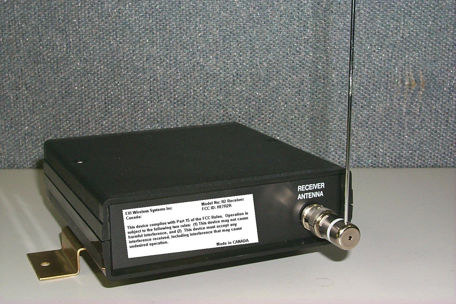
Label for the receiver. Size: 1.14 x 3.15 in (29 x 80 mm) This label will be placed on the side of the receiver as approximated on the "R2 receiver.jpg" picture. EXI Wireless Systems Inc Model No: R2 Receiver Canada: FCC ID: HE7R2R This device complies with Part 15 of the FCC Rules. Operation is subject to the following two rules: (1) This device may not cause harmful interference, and (2) This device must accept any interference received, including interference that may cause undesired operation. Made in CANADA
Parts List/Tune Up Info
5/17/01 EXI-202-A2 ROAM II RECEIVER PCA (600-000011-000) PARTS LIST # SITE EXI # PART VALUE Description Manufacturer Supplier Quantity 01 C6 4-01111 T491D106K035AS 10 μF capacitor, tantalum, SMD, 35V, 10% KEMET Electrosonic 1 02 C7,C8 ,C85 4-01105 T491B105K035AS 1.0 μF capacitor, tantalum, SMD, 35V, 10% KEMET Electrosonic 3 03 C9 4-01113 T491C106K016AS 10 μF capacitor, tantalum, SMD, 16V, 10% KEMET Electrosonic 1 04 C10 , C24, C86 4-01104 B37872K5104K62 100 nF capacitor, SMD, 1206, 50V, 10% SIEMENS Electrosonic 3 05 C13, C106 4-01116 B37941K5103K62 10 nF capacitor, SMD, 0805, 50V, 10% SIEMENS Electrosonic 2 06 C21, C22 B37940K5180J62 18pF capacitor, SMD, 0805, 50V, 5% SIEMENS Electrosonic 2 07 C33,C83 4-01119 B37940K5560J62 56 pF capacitor, SMD, 0805, 50V, 5% SIEMENS Electrosonic 2 08 C34,C90 4-01120 B37940K5561J62 560 pF capacitor, SMD, 0805, 50V, 5% SIEMENS Electrosonic 2 09 C38 4-01117 T491B225K020AS 2.2 μF capacitor, tantalum, SMD, 20V, 10% KEMET Electrosonic 1 10 C42,C43 ,C84, C100 4-01109 B37941K5102K62 1.0 nF capacitor, SMD, 0805, 50V, 10% SIEMENS Electrosonic 4 11 C80,C81 4-01126 B37940K5220J62 22 pF capacitor, SMD, 0805, 50V, 5% SIEMENS Electrosonic 2 12 C82 4-01127 B37940K5820J62 82 pF capacitor, SMD, 0805, 50V, 5% SIEMENS Electrosonic 1 13 C87,C88, C104 4-01106 B37940K5330J62 33 pF capacitor, SMD, 0805, 50V, 5% SIEMENS Electrosonic 3 14 C89 4-01128 B37940K5010C562 1.5 pF capacitor, SMD, 0805, 50V, 5% SIEMENS Electrosonic 1 15 C98 1-01048 353-037-50221 220μF capacitor, electrolytic, 35V, 20% PHILIPS 1 16 C99, C105 B37940K5020C762 2.7 pF capacitor, SMD, 0805, 50V, 5% SIEMENS Electrosonic 2 17 C101 4-01114 ECU-V1H050CCN 100 pF capacitor, SMD, 0805, 50V, 5% PANASONIC Digi-Key 1 18 C102 B37940K5030C362 3.3 pF capacitor, SMD, 0805, 50V, 5% SIEMENS Electrosonic 1 1920 L7, L8, L11 4-13424 ELJ-RE68NJF3 68 nH inductor, SMD, 0603, 5% PANASONIC Digi-Key 3 21 L3, L10 4-13425 ELJ-RE47NJF2 47 nH inductor, SMD, 0603, 5% PANASONIC Digi-Key 2 22 L4 4-13426 ELJ-RE18NJF2 18 nH inductor, SMD, 0603, 5% PANASONIC Digi-Key 1 Page 1 5/17/01 EXI-202-A2 ROAM II RECEIVER PCA (600-000011-000) PARTS LIST # SITE EXI # PART VALUE Description Manufacturer Supplier Quantity 23 R1, R180, R189 4-08171 2.7 kOhm resistor, SMD, 0.5W, 2010, 5% 3 24 R13 4-08161 470 Ohm resistor, SMD, 0.1W, 0805, 5% 1 25 R14 4-08162 12 kOhm resistor, SMD, 0.1W, 0805, 5% 1 26 R15 ,R174,R175 4-08163 47 kOhm resistor, SMD, 0.1W, 0805, 5% 3 27 R16, R60 4-08149 100 kOhm resistor, SMD, 0.1W, 0805, 5% 2 28 R176 4-08194 18 kOhm resistor, SMD, 0.1W, 0805, 5% 1 29 R181 4-08152 4.7 kOhm resistor, SMD, 0.1W, 0805, 5% 1 30 R182 4-08196 390 kOhm resistor, SMD, 0.1W, 0805, 5% 1 31 R187 4-08158 82 Ohm resistor, SMD, 0.5W, 2010, 5% 1 32 R190, R191 160 Ohm resistor, SMD, 0.5W, 2010, 5% 2 33 R192, R193 0 Ohm resistor, SMD, 0.1W, 0805 2 34 R32 4-08167 22 Ohm resistor, SMD, 0.1W, 0805, 5% 1 35 R33,R34 4-08168 33 kOhm resistor, SMD, 0.1W, 0805, 5% 2 36 R35,R36 4-08169 820 Ohm resistor, SMD, 0.1W, 0805, 5% 2 37 R38 4-08176 1.0 kOhm resistor, SMD, 0.1W, 0805, 5% 1 38 R57 4-08178 5.1 kOhm resistor, SMD, 0.1W, 0805, 5% 1 39 R58 4-08179 24 kOhm resistor, SMD, 0.1W, 0805, 5% 1 40 R59 4-08180 51 kOhm resistor, SMD, 0.1W, 0805, 5% 1 41 R61 4-08181 200 kOhm resistor, SMD, 0.1W, 0805, 5% 1 42 R88, R188 4-08166 10 kOhm resistor, SMD, 0.1W, 0805, 5% 2 43 R95, R96 4-08202 1.5 kOhm resistor, SMD, 0.1W,0805,5% 2 44 R98 4-08204 390 Ohm resistor, SMD, 0.1w, 0805, 5% 1 45 R173 150kOhm resistor, SMD, 0.1W, 0805, 5% 1 464748 D1 4-03019 DL4002 diode, SMD,1A, 100V NS 1 49 D10, D14 4-03021 MMBD914LT1 diode, SMD, 70V, 200mA MOTOROLA 2 50 D12,D13 4-03022 MLL4736 ZENER diode, SMD, 6.8V, 1W MOTOROLA / NS 2 51 D2 1-13119 HLMP-1302-010 LED, red HEWLET-PACK Electrosonic 1 52 D32 1-13115 HLMP-1523-010 LED, green HEWLET-PACK Electrosonic 1 53 D34 1-13121 HLMP-1402-010 LED, yellow HEWLET-PACK Electrosonic 1 5455 DV1 4-03027 SMV1235-011(1104-35) VARACTOR diode ALPHA 1 5657 Q6, Q14, Q15, Q31 4-11016 MMBT3904LT1 transistor, NPN, SMD MOTOROLA 4 Page 2 5/17/01 EXI-202-A2 ROAM II RECEIVER PCA (600-000011-000) PARTS LIST # SITE EXI # PART VALUE Description Manufacturer Supplier Quantity 58 Q1 MMBR941LT1 transistor, NPN, SMD MOTOROLA Active/Fai 1 59 U11 4-04112 LM2904D dual OP-AMP, SMD MOTOROLA Active/FAI 1 60 U16 4-04109 PIC16C63-20/P microcontroller MICROCHIP Active/FAI 1 61 U16.1 (SOCKET for U16) 1-09007 28 PIN SOCKET, 300 MILS WIDE, Robinson Nugen Active/FAI 1 62 U3,U4 4-04106 MC78L05 voltage regulator, TO-92, 5V, 100mA MOT., TI Active/FAI 2 63 U5 4-04107 KESRX01 ASK RF receiver, SMD GEC Plessey GMA 1 64 U75 1-13271 LM7812 voltage regulator, TO-220, 12V, 1 amp NATIONAL Active/FAI 1 65 U75.1 385-257 4-40, 1/4" pan-head machine screw SPAENAUR 1 66 U75.2 B-753 4-40 hex machine screw nut SPAENAUR 1 U75.3 54-SN No. 4 tooth lockwasher SPAENAUR 1 67 F1 4-13429 218.500 fuse, 0.5A, slow blow LITTLEFUSE 1 68 F1.1 1-13073 111501 fuse clip LITTLEFUSE 2 6970 RY1 1-13189 G6A-274P-ST-US-DC12 relay, DPDT,2A OMRON Electrosonic 1 7172 X1 4-13431 A-20.000000-18 20 MHz crystal RALTRON Electrosonic 1 73 X4 4-13434 A-6.77578-18 6.77578 MHz crystal RALTRON Electrosonic 1 74 X1.1, X4.1 CI-192-028 crystal Insulators for X1 & X4 BIVAR 2 7576 SF1 RF1172 433.92 MHz SAW filter RFM Kaytronics 1 77 SF1.1 520-021 SAW filter insulator BIVAR Active/FAI 1 78 S7 4-10025 DRD16 switch, rotary DIP, thru-hole AUGAT Electrosonic 1 7980 J6, J7 1-13348 TSW-103-14-T-S terminal strip SAMTEC 2 81 J6.1, J7.1 1-13335 cat.# 36-100-0 shunt MODE Electrosonic 2 8283 P1 4-02077 590-001-00/50 connector, BNC, right-angle A/D Electronics A/D Electronics 1 84 P3 4-02094 120-M-411/10 header WECO 1 85 P3.1 4-02093 120-A-111/10 horizontal plug WECO 1 8687 TP2, TP6, TP10, GROUND PIN TSW-101-14-T-S terminal pin SAMTEC 4 888990 EXI-202-A2 PCB 1 Page 3 5/17/01 EXI-202-A2 ROAM II RECEIVER PCA (600-000011-000) PARTS LIST Page 4 5/17/01 EXI-202-A2 ROAM II RECEIVER PCA (600-000011-000) PARTS LIST Page 5 5/17/01 EXI-202-A2 ROAM II RECEIVER PCA (600-000011-000)…
Text truncated - open the document above for the full version.
Test Report
Master: ktlPT15BR Date: October 8, 1999 KTL Test Report:9R05172.1 Applicant:EXI Wireless Systems Inc. Suite 100-13551 Commerce Parkway Richmond, B.C. V6V 2L1 Equipment Under Test:Standalone Super-Heterodyne Receiver (E.U.T.) FCC ID:HE7R2R In Accordance With:FCC Part 15, Subpart B Radio Receivers Tested By:KTL Ottawa Inc. 3325 River Road, R.R. 5 Ottawa, Ontario K1V 1H2 Authorized By: R. Grant, Wireless Group Manager Date: Total Number of Pages:19 KTL OttawaFCC PART 15, SUBPART B RADIO RECEIVERS PROJECT NO.: 9R05172.1 EQUIPMENT: Standalone Super-Heterodyne Receiver FCC ID: HE7R2R Page 2 of 19 Table Of Contents Section 1. Summary of Test Results .....................................................................................................3 Section 2. Equipment Under Test (E.U.T.) ..........................................................................................5 Section 3. Receiver Antenna Conducted Emissions......................................…
Text truncated - open the document above for the full version.
Contact Information
Applicant
Chris Bisaillion(Senior RF Designer)
Technical Contact
Non-Technical Contact
KTL OTTAWARUBY C DULMAGE
[email protected]800-563-6336
Test Firm
Nemko Canada Inc.Stuart Beck
Technical Specifications
| # | Rule Parts | Frequency Range | Power Output |
|---|---|---|---|
| 1 | 15B | 434 MHz - 434 MHz | - |
Other Applications from Xmark Corporation
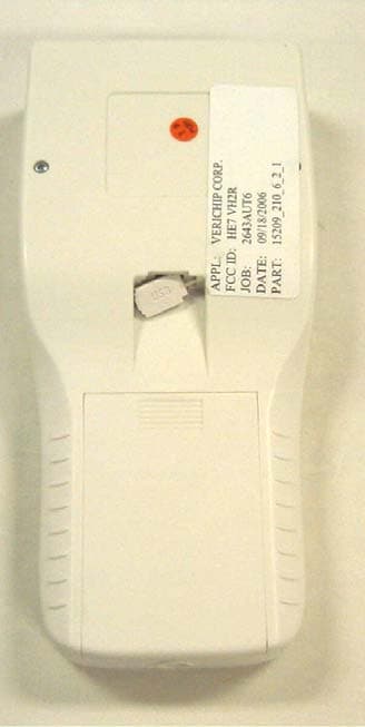
HE7VH2R
Oct 18, 2006VERICHIP H2 READER
Equipment Class
DXX - Part 15 Low Power Communication Device Transmitter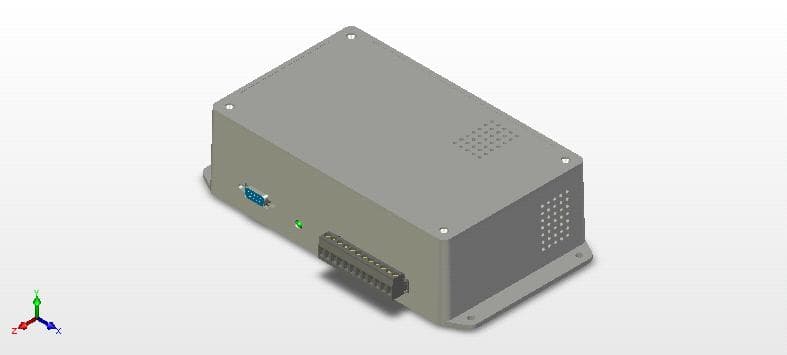
HE7VACR
May 21, 2006VERIGUARRD ACCESS CONTROL READER
Equipment Class
DXX - Part 15 Low Power Communication Device Transmitter
HE7PCR
Apr 06, 2005Receiver
Equipment Class
CYY - Communications Receiver used w/Pt 15 Transmitter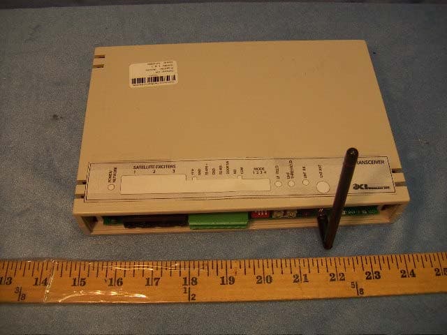
HE7EAC
Feb 07, 2005Transceiver
Equipment Class
DCD - Part 15 Low Power Transmitter Below 1705 kHz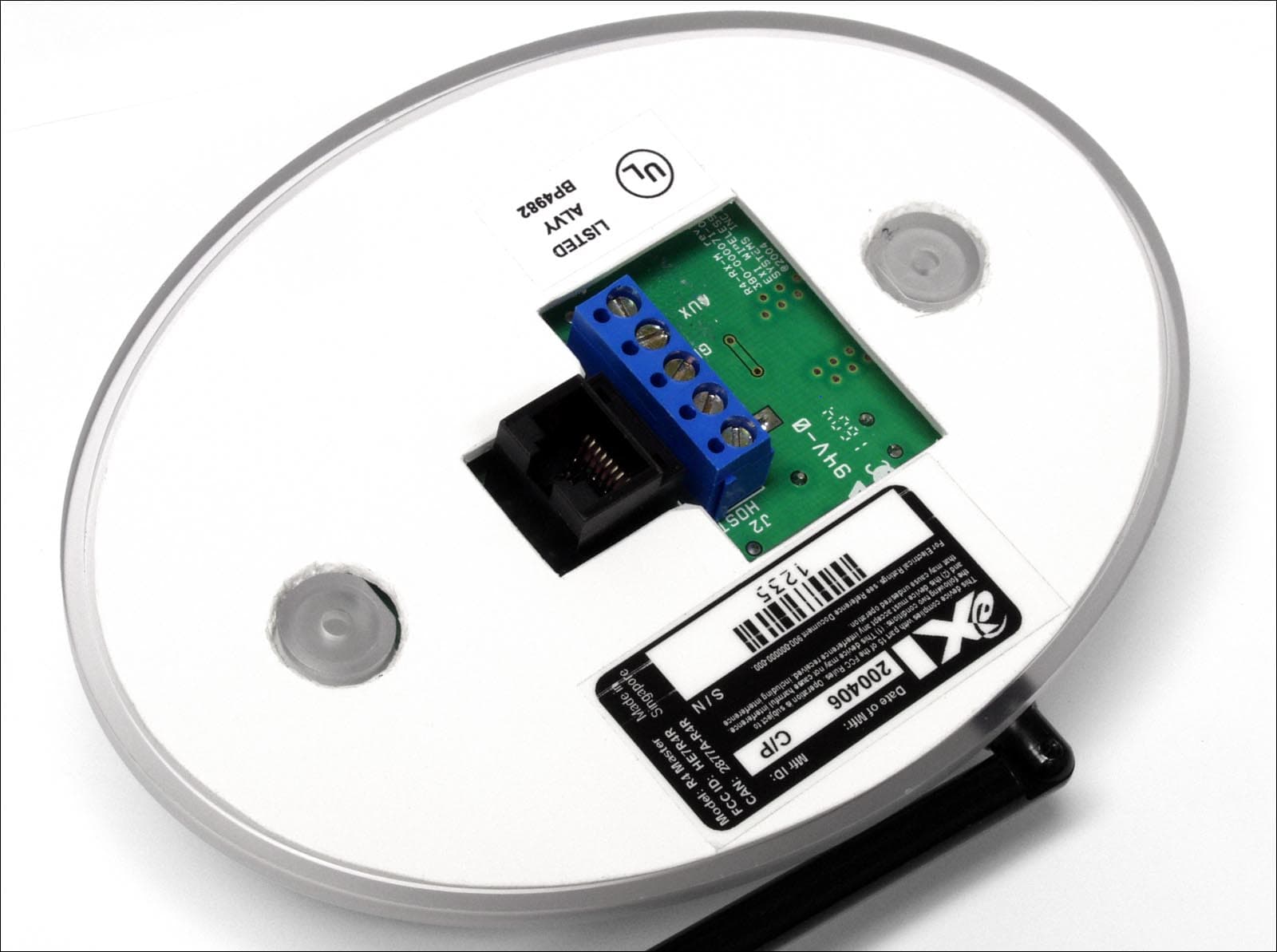
HE7R4R
Oct 13, 2004Communications Receiver
Equipment Class
CYY - Communications Receiver used w/Pt 15 Transmitter