HE7WKPWireless Keypad
Xmark Corporation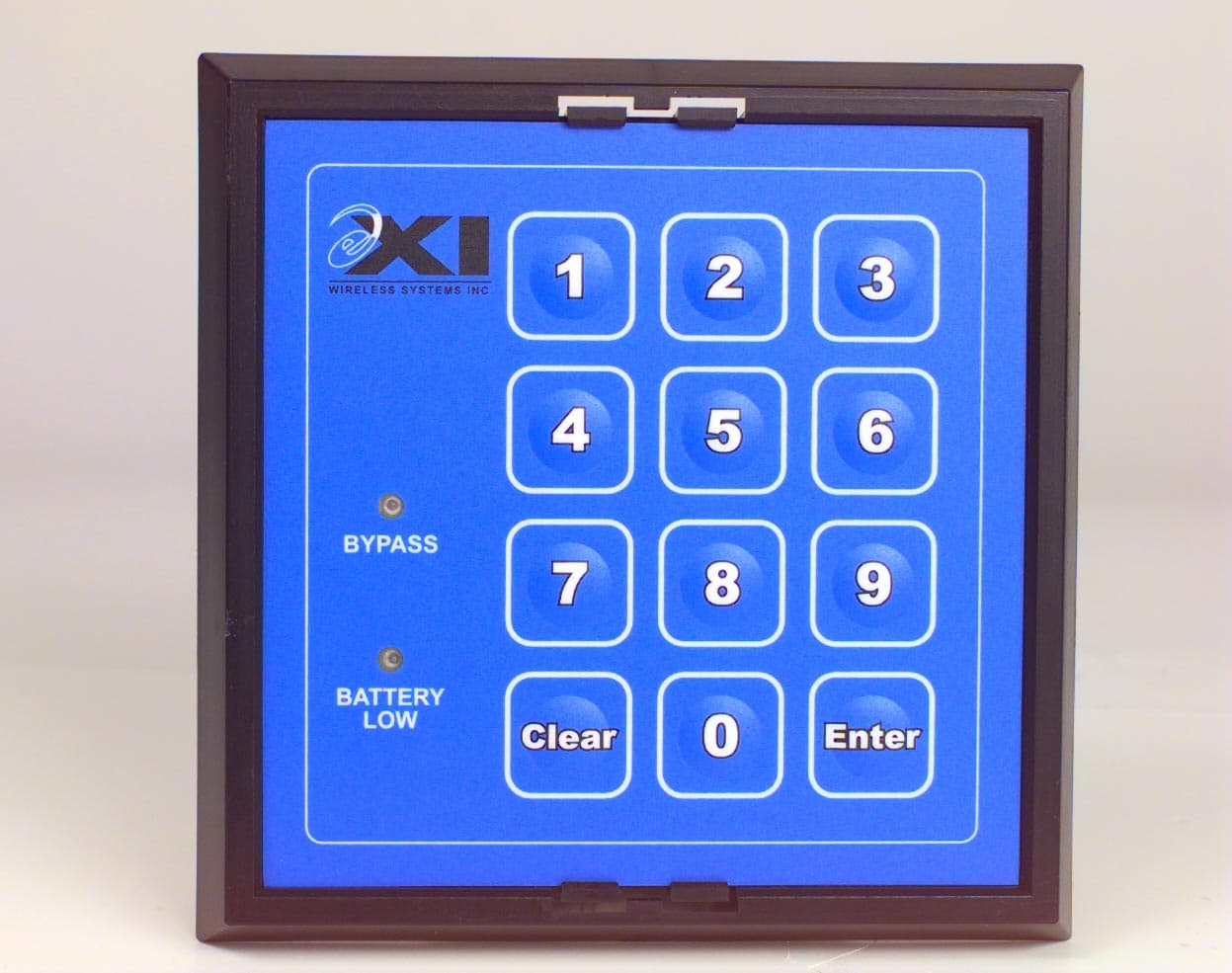
Click to zoom
Application Details
- Equipment Class
- DSC - Part 15 Security/Remote Control Transmitter
- Date of Grant
- Jun 25, 2000
- Application Purpose
- Original Equipment
- Date of Application
- Jun 12, 2000
- Equipment Note
- Wireless Keypad
- Frequency Range
- 433.92000000 - 433.92000000
- Company
- Xmark Corporation
- Country
- Canada
Documents & Files
Document Text
Text extracted from the exhibit documents filed with the FCC. Open a document above to read the original.
Users Manual
Revision 1.0 Installation & User Manual May 2000 © Copyright 2000, EXI Wireless Systems Inc. All rights reserved. EXI ECO-Lite User Manual 980-000004-000 EXI Wireless Systems 2 May 2000 Revision 1.0 Table of Contents 1. Limited Warranty.................................................................................................................................. 3 2. Record of Changes ................................................................................................................................ 4 3. FCC Regulations ................................................................................................................................... 5 4. Introduction........................................................................................................................................... 6 5. Initializing the ECO-Lite System .......................................................................................................... 7 6. ECO-Lite Controller ............................................................................................................................. 8 7. Wireless Keypad ................................................................................................................................... 9 8. Bypassing / Escorting Patients .............................................................................................................. 9 9. Accepting Alarms ................................................................................................................................. 9 10. Password Management.................................................................................................................... 10 10.1. Master Password ..................................................................................................................... 10 10.2. User password ......................................................................................................................... 10 11. Operational Mode Change .............................................................................................................. 11 12. System Settings ............................................................................................................................... 11 12.1. Test Mode “51”....................................................................................................................... 11 12.2. Normal Mode with fixed alarm duration “52” ........................................................................ 11 12.3. Normal Mode with unlimited alarm duration “53” ................................................................. 11 13. Assigning the Keypad to the Controller ..........................................................................................12 14. Tamper Alarm ................................................................................................................................. 12 15. Wrist Tags....................................................................................................................................... 12 16. Power Supply .................................................................................................................................. 12 17. Controller Enclosure ....................................................................................................................... 13 18. Wireless Keypad Enclosure ............................................................................................................ 13 EXI ECO-Lite User Manual 980-000004-000 EXI Wireless Systems 3 May 2000 Revision 1.0 1. Limited Warranty EXI Wireless Systems Inc. (“EXI”) hereby warrants the product(s) accompanying this limited warranty (the “Product(s)”) to be free of defects in materials and workmanship for a period of two years (excluding any batteries that may be added to or used in conjunction with the Products(s)) from the date of delivery of the original purchase of the Product(s) subject to the limiting conditions set forth below, provided that EXI has received notification of such defects no later than 30 days after expiration of the applicable warranty period and provided further that EXI has received a fully completed registration card (below) within 30 days from the date of original purchase of the Product(s). The responsibility of EXI under this warranty is and shall be limited to repairing or replacing the Product(s) or any part thereof determined by EXI in its sole discretion to be defective in workmanship or material. The installation of the Product(s) shall be deemed as acceptance by the original purchaser and any subsequent purchaser of the Product(s) (collectively the “Purchaser”) of the terms set out in this limited warranty including the following further limiting conditions: (a) EXI shall not be responsible for any repair or replacement of any Product(s) which has been found, upon inspection, to have been subjected to abuse, misuse or negligence, or any damage attributable to accident, lightning, power surge, brown-out, leaking, damaged or inoperative batteries or to have been installed, altered or repaired contrary to factory designated procedures without the prior written consent of EXI; (b) It is understood, and the Purchaser agrees further to so inform any user of the Product(s) that the Product(s) is not, nor can it be, infallible in the detection of wandering patients, the prevention of infant abduction, the prevention of theft of assets or any other contemplated use of the Product(s). The Purchaser will warn all users and acknowledges on it’s own behalf that it has read and understands the above-mentioned limitations of the Product(s). The Purchaser further acknowledges that the Product(s) are solely intended to provide an additional safeguard in notifying staff and accordingly do not guarantee the prevention of wandering patients or the attempted abduction of an infant or the theft of a…
Text truncated - open the document above for the full version.
ID Label/Location Info
C:\vcadd\rfkeypad\fcclabel.vcd 5/10/2000C:\vcadd\rfkeypad\fcclabel.vcd 5/10/2000 Sheet: Size: Document Number: Rev Title: EXI Wireless Systems Inc. Date: REAR VIEW REAR VIEW, TOP BATTERY CODE SWITCH CUT OUT EXPOSING PCA FCC ID: HE7 WKP WIRELESS KEYPAD, FCC ID Location ECO#REVNOTES A932-000086-000 P1 10 May, 2000 1 of 1
Operational Description
Wireless Keypad___________________________________________________________953-000001-000 EXI Wireless Systems 953-000001-000 Wireless Keypad___________________________________________________________953-000001-000 EXI Wireless Systems 953-000001-000 ECO Lite Wireless Keypad Circuit Description Revision 1.0 April 19, 2000 953-00001-000 1. Document Purpose The purpose of this document is to describe Wireless Keypad circuitry for the Low Cost CPM. Wireless Keypad___________________________________________________________953-000001-000 EXI Wireless Systems 953-000001-000 2. Introduction This document provides basic description of the Wireless Keypad circuits from the hardware point of view. The firmware overview can be find in the document 940-000002-000. The primary goal of this project was to develop a low cost battery operated Wireless Keypad for ECO Lite system. To achieve these goals we have used mostly discrete components for this design and the microcontroller is powered up when external interrupt is generated or a message transmission is needed only. The Keypad circuitry can be divided into blocks for description purpose as well as for easy troubleshooting. Wireless Keypad___________________________________________________________953-000001-000 EXI Wireless Systems 953-000001-000 2 1 3 4 5 6 ENTER 8 9 7 CLEAR 0 BYPASS BATT LOW Fig. 1 Ke ypad La yo ut 3. Circuit Description 3.1 Timing circuit The keypad timing is based on simple RC charge circuit. We can use this very simple configuration because timing is not critical for any of the keypad functions. This used configuration generates approximately 8 second cycle. This circuit is running all the time, so a high value resistor is used for Vcc connection to decrease a power consumption of this circuit. 3.2 Battery check circuit The battery check circuit is based on two differential circuits and inverter to control the LED indicating low battery voltage. This battery check is activated at time base interval. A single LED is used as reference for comparing battery voltage. A set point for low battery indication is 2.75V. Another simple RC circuit is Wireless Keypad___________________________________________________________953-000001-000 EXI Wireless Systems 953-000001-000 used for the low battery volta ge w arning to be sent to the co ntroller. The co nfi guratio n used here gives us time base approximately 30 minutes. 3.3 Keypad circuit The keypad is organized in 3x4 matrix. All three columns are connected through inverters to PIC inputs able to generate interrupt. When any key is pressed the analog switch is activated to connect power to PIC microcontroller. Then interrupt recognition process starts to find out source of the interrupt (keypad, low battery voltage, or tamper switch). The proper message is transmitted to the controller. 3.4 Tamper switch circuit The keypad mounted in the bezel is protected against unauthorized removing by a tamper switch circuit. The circuit uses a magnetic reed switch (normally closed) and a small magnet glued to the bezel. If keypad is removed from the bezel the magnetic field holding the reed switch open is lost and voltage from a simple RC circuit ge nerates an i nterrup t si milar to the keypad i nterr upt. Because no ne of the ke ys is pressed the microcontroller decodes this situation as a tamper switch interrupt and alarm message is sent to the controller. To disable the alarm (controller is beeping ) the proper password must be entered on the keypad. When the keypad is placed back to the bezel it takes approximately 20 seconds before the tamper switch circuit is ready to protect the keypad again. 3.5 Transmitter circuit The keypad transmitter is using 433.92 MHz frequency to communicate with the controller. The antenna is a small surface mount inductor. The microcontroller output controlling the transmitter normally maintains high-level signal to keep RF transistor disable. 3.6 Microcontroller and memory circuits The PIC16LC505 microcontroller is used for controlling all keypad’s activities. The both Master and User customized passwords are stored into an external serial EEPROM. The eight position rotary switch with a serial shift register is used for the ID number selection. This allows selecting specific communication path between the keypad and controller. An internal delay timer is used to power down microcontroller after each task is finished.
Parts List/Tune Up Info
6/14/00 ECO-LITE CONTROLLER PC ASSEMBLY BOM page 1 of 2 Bill of Material: ECO-Lite Wireless Keypad PCB Assembly: 600-000034-000 Item # EXI # DESCRIPTION QTY SCHEMATIC REF Alternate EXI # MFR MFG PN 1 380-000012-000 PCB, ECO LITE Wireless Keypad 1 2 303-000001-000 Battery, Li-Mn, Size 2032, 230mAH, 3V, with Straight Horiz. Tabs, -30 to +70C 1 BT1 Panasonic CR2032-SM 3 110-002023-105 CAP, 1uF, SMD, Tantalum, 35V, 10%, -55 to +125C, B size 3 C1, C12, C14 Matsuo 267M3502105KR 4 110-000042-103 CAP, 10nF, SMD, 0805, X7R, 25V, 10%, -55 to +125C 2 C2, C11 Kemet C0805C103K3RAC 5 110-000039-102 CAP, 1000pF, SMD, 0805, NPO, 50V, 5%, -55 to +125C 2 C3, C8 Panasonic ECUV1H102JCX 6 110-000037-3P9 CAP, 3.9pF, SMD, 0805, NPO, 50V, +/-0.5pF, -55 to +125C 1 C4 Kemet C0805C399D5GAC 7 110-002022-475 CAP, 4.7uF, SMD, Tantalum, 25V, 10%, -55 to +125C, B size 1 C5 Matsuo 267E2502475KR 8 110-000042-104 CAP, 100nF, SMD, 0805, X7R, 25V, 10%, -55 to +125C 2 C6, C13 Kemet C0805C104K3RAC 9 110-000039-120 CAP, 12pF, SMD, 0805, NPO, 50V, 5%, -55 to +125C 1 C7 Panasonic ECUV1H120JCN 10 110-002006-474 CAP, 0.47uF, SMD, Tantalum, 25V, 10%, -55 to +125C, A size 1 C9 Matsuo 267M2502474KR 11 200-000008-000 Diode, Switching, 100mA, 70V, 225mW, SOT-23, -55 to +150C 4 D1, D2, D5, D6 Motorola BAL99LT1 12 201-000001-000 Diode, Ultra Fast Switch., Dual, Com. Cath., 300mA, SOT-23, -55 to +150C 2 D11, D14 Rohm BAV70 13 330-000005-002 LED, Z-Bend Lead, Green, Water Clear, 20mCD@20mA, 25 degrees 1 D12 Lumex SSL-LXA228GC-TR31 14 330-000006-000 LED, SMD, 1206, Green, Clear, 12mCD@20mA, 70 degrees 1 D31 Lumex SML-LX1206GC-TR 15 330-000004-002 LED, Z-Bend Lead, Super Red, Water Clear, 170mCD@20mA, 25 degrees 1 D4 Lumex SSL-LXA228SRC-TR31 16 201-000002-000 Diode, Ultra Fast Switch., Dual, Com. Anode, 300mA, SOT-23, -55 to +150C 1 D9 Rohm BAW56 17 120-000004-220 Inductor, 22nH, SMD, Size 1008, High-Q, 5%, -40 to +125C 1 L1 Coilcraft 1008CS-220XJBC 18 204-000002-000 Transistor, PNP, SOT-23, Vceo=40V, Ic=200mA 6 Q1, Q2, Q3, Q7, Q8, Q10 Motorola MMBT3906LT1 19 204-000001-000 Transistor, NPN, SOT-23, Vceo=40V, Ic=200mA 2 Q4, Q5 Motorola MMBT3904LT1 20 204-000008-000 Transistor, NPN, VHF/UHF, SOT-23, Vceo=25V, 225mW, -55 to +150C 1 Q6 Motorola MMBTH10LT1 21 204-000009-000 Transistor, N-chan MOSFET, SOT-23, Vds=20V, 0.39A, -55 to +150C 1 Q9 Vishay/Siliconix TN0201T 22 100-000013-103 RES, 10K, SMD, 5%, 1/10W, 0805, -55 to +125C 3 R1, R12, R42 Panasonic ERJ6GEYJ103V 23 100-000013-683 RES, 68K, SMD, 5%, 1/10W, 0805, -55 to +125C 6 R13, R15, R24, R26, R27, R29 Panasonic ERJ6GEYJ683V 24 100-000013-225 RES, 2.2M, SMD, 5%, 1/10W, 0805, -55 to +125C 6 R14,18,19,20,33,39 Panasonic ERJ6GEYJ225V 25 100-000013-331 RES, 330, SMD, 5%, 1/10W, 0805, -55 to +125C 2 R16, R32 Panasonic ERJ6GEYJ331V 26 100-000013-106 RES, 10M, SMD, 5%, 1/10W, 0805, -55 to +125C 4 R2, R4, R38, R43 Panasonic ERJ6GEYJ106V 27 100-000013-334 RES, 330K, SMD, 5%, 1/10W, 0805, -55 to +125C 1 R22 Panasonic ERJ6GEYJ334V 28 100-000013-821 RES, 820, SMD, 5%, 1/10W, 0805, -55 to +125C 1 R23 Panasonic ERJ6GEYJ821V 29 100-000013-474 RES, 470K, SMD, 5%, 1/10W, 0805, -55 to +125C 5 R25, R30, R35, R36, R37 Panasonic ERJ6GEYJ474V 30 100-000013-104 RES, 100K, SMD, 5%, 1/10W, 0805, -55 to +125C 6 R3, R10, R11, R17, R21, R28 Panasonic ERJ6GEYJ104V 31 100-000013-206 RES, 20M, SMD, 5%, 1/10W, 0805, -55 to +125C 1 R34 KOA RM73B2AT206J 32 100-000013-102 RES, 1K, SMD, 5%, 1/10W, 0805, -55 to +125C 1 R40 Panasonic ERJ6GEYJ102V 33 100-000013-226 RES, 22M, SMD, 5%, 1/10W, 0805, -55 to +125C 1 R41 KOA RM73B2AT226J 34 100-000013-333 RES, 33K, SMD, 5%, 1/10W, 0805, -55 to +125C 3 R5, R6, R31 Panasonic ERJ6GEYJ333V 35 100-000013-134 RES, 130K, SMD, 5%, 1/10W, 0805, -55 to +125C 1 R7 Panasonic ERJ6GEYJ134V 36 100-000013-823 RES, 82K, SMD, 5%, 1/10W, 0805, -55 to +125C 1 R8 Panasonic ERJ6GEYJ823V 37 100-000013-223 RES, 22K, SMD, 5%, 1/10W, 0805, -55 to +125C 1 R9 Panasonic ERJ6GEYJ223V 38 310-000001-000 Switch, Rotary, Octal (8-pos.), SMD, Sealed 1 SW1 Grayhill 94HAB08W 39 312-000002-000 Switch, Reed, Pull-in Range 15-25 A-turns, 5W, 175V, 0.25A, -40 to +125C 1 SW2 Hamlin MDRR-DT 15-25 40 210-000003-000 IC, Quad Analog Switch, CMOS, 4066, SO-14, -55 to +125C 1 U1 Motorola MC14066BD 41 210-000001-000 IC, Hex Inverter, CMOS, 4069, SO-14, -55 to +125C 3 U2, U5, U7 Motorola MC14069UBD 42 210-000004-000 IC, 8-bit Shift Reg., Async. P-to-S, CMOS, 4021, SO-16, -55 to +125C 1 U3 Motorola MC14021BD 43 601-000002-000 Programmed PIC for ECO Lite Wireless Keypad 1 U4 44 212-000001-001 IC, Serial EEPROM, I2C, SO-8, 1Kbits, 1.8V-5.5V, 0 to 70C 1 U6 Microchip 24AA01T/SN 45 124-000001-000 Resonator, SAW, 433.92MHz,+/-75kHz, SMD, -40 to +85C 1 Y1 RFM RO2101A 46 911-000012-000 Schematic, ECO Lite Wireless Keypad 0 600-000029 REV 1.1 Apr 7,2000 RELEASED FOR 30 PIECE PILOT BUILD 6/14/00 ECO-LITE CONTROLLER PC ASSEMBLY BOM page 2 of 2 47 932-000077-000 Assembly Instructions, ECO Lite Wireless Keypad PCB Assembly 0 48 931-000018-000 Manufacturing Test Spec., ECO LIte Wireless Keypad PCB Assembly 0 49 953-000001-000 Detailed Circuit Description, ECO Lite Wireless Keypad 0 600-000029 REV 1.1 Apr 7,2000 RELEASED FOR 30 PIECE PILOT BUILD
Schematics
5 5 4 4 3 3 2 2 1 1 DD CC BB AA EXI WIRELESS SYSTEM INC 911-0000012-000 1.0 Wireless Keypad 11Thursday, March 30, 2000 Title SizeDocument NumberRev Date:Sheetof V1 B B Vbat Vbat Vbat Vbat Vbat Vbat VbatVbat C11 10nF R192M2 C8 1nF U1C MC14066B 8 9 6 8 9 C R31 33K R2 10M R202M2 U1B MC14066B 4 3 5 4 3 C R3 100K Y1 433.92MHz Q6 MMBTH10L R4 10M R7 130K R8 82K R36 470K U7A 14069 12 Q9 TN0201T 3 1 2 + C9 0.47uf R37 470K R10 100K R12 10K D11A BAV70 R35 470K D12 LED R5 33K U4 PIC16LC505-04/SL 10 9 8 7 13 12 11 4 3 2 1 14 6 5 RC0 RC1 RC2 RC3 RB0 RB1 RB2 RB3 RB4 RB5VDD VSS RC4 RC5 R6 33K R30470K R11 100K R33 2M2 C2 10nF D31 Green LED + C14 1uF U2B 14069 34 14 7 D2 BAL99LT1 J1 RSTpasswrd 12 12 Q4 MMBT3904 3 1 2 U7B 14069 34 Q5 MMBT3904 3 1 2 U7E 14069 1110 Q7 MMBT3906 3 1 2 U1A MC14066B 1 2 13 1 2 C R39 2M2 U2C 14069 56 14 7 D14A BAV70 C6 .1uF U5B 14069 34 R25 470K U5F 14069 1312 R38 10M R34 20 M U7F 14069 1312 U5A 14069 12 D6 BAL99LT1 + C5 4.7uF C13 100nF U2E 14069 1110 R4210K U2F 14069 1312 R4310M R41 22M SW1 SW OCTAL 652 341 R2968K U1D MC14066B 11 10 12 11 10 C R2768K U7D 14069_0 98 U7C 14069 56 R2668K Q1 MMBT3906 3 1 2 R9 22K R2468K D11B BAV70 Q3 MMBT3906 3 1 2 Q2 MMBT3906 3 1 2 Q10 MMBT3906 3 1 2 R1 10K D4 LED L1 220XGB 21 R16 330 R13 68K D9B BAW56 + C12 1uF R14 2M2 R15 68K U2D 14069 98 R21 100K U6 24AA01-SM 1 2 3 4 5 6 7 8 A0 A1 A2 VSS SDA SCL WP VCC C3 1nF R23820 U5C 14069 56 C4 3.9pF U3 4021 11 7 6 5 4 13 14 15 1 10 9 2 12 3 16 8 SER A B C D E F G H CLK P/S QF QG QH Vbat VSS D1 BAL99LT1 C7 12pF U5D 14069 98 D5 BAL99LT1 + 3V1 BT1 0 1 U5E 14069 1110 Q8 MMBT3906 3 1 2 D14B BAV70 R32 330 R28100K R17 100K R40 1K SW2 SW Reed + C1 1uF U2A 14069 12 1 2 36 5 9 8 7* 0 # 4 KP1 Keypad K L M NOPQ K L M NO P Q D9A BAW56 R182M2 R22 330K
Test Report
Master: ktlPT15231 Date: April 5, 2000 KTL Test Report:0R02491 Applicant:EXI Wireless Systems Inc. Suite 100-13551 Commerce Parkway Richmond, BC V6V 2L1 Equipment Under Test:Wireless Keypad (E.U.T.) FCC ID:HE7 WKP In Accordance With:FCC Part 15, Subpart C For Low Power Transmitters Operating Periodically In The Band 40.66 - 40.77 MHz And Above 70 MHz Tested By:KTL Ottawa Inc. 3325 River Road, R.R. 5 Ottawa, Ontario K1V 1H2 Authorized By: R. Grant, Wireless Group Manager Date: Total Number of Pages:25 KTL Ottawa FCC PART 15, SUBPART C FOR LOW POWER TRANSMITTERS PROJECT NO.: 0R02491 EQUIPMENT: Wireless Keypad FCC ID: HE7 WKP Page 2 of 23 Table of Contents Section 1. Summary of Test Results.......................................................................................... 3 Section 2. Equipment Under Test (E.U.T.) .............................................................................. 5 Section 3. Transmission Requirements .................................................................................. 13 Section 4. Occupied Bandwidth.............................................................................................. 16 Section 5. Periodic Alternate Field Strength Requirements................................................ 19 Section 6. Block Diagrams.......................................................................................................22 Section 7. Test Equipment List ............................................................................................... 23 Annex A Restricted Bands................................................................................................... A1 KTL Ottawa FCC PART 15, SUBPART C FOR LOW POWER TRANSMITTERS PROJECT NO.: 0R02491 EQUIPMENT: Wireless Keypad FCC ID: HE7 WKP Page 3 of 23 Section 1.Summary of Test Results General All measurements are traceable to national standards. These tests were conducted on a sample of the equipment for the purpose of demonstrating compliance with Part 15, Subpart C, Paragraph 15.231. All tests were conducted using measurement procedure ANSI C63.4-1992. Radiated emissions are made on an open area test site. A description of the test facility is on file with the FCC. New SubmissionProduction Unit Class II Permissive ChangePre-Production Unit DS C Equipment Code THIS TEST REPORT RELATES ONLY TO THE ITEM(S) TESTED. THE FOLLOWING DEVIATIONS FROM, ADDITIONS TO, OR EXCLUSIONS FROM THE TEST SPECIFICATIONS HAVE BEEN MADE. See “ Summary of Test Data”. NVLAP LAB CODE: 100351-0 TESTED BY: _____________________________________ DATE: ___________________ Kevin Carr, Technologist KTL Ottawa Inc. authorizes the above named company to reproduce this report provided it is reproduced in its entirety and for use by the company’s employees only. Any use which a third party makes of this report, or any reliance on or decisions to be made based on it, are the responsibility of such third parties. KTL Ottawa Inc. accepts no responsibility for damages, if any, suffered by any third party as a result of decisions made or actions based on this report. This report applies only to the items tested. KTL Ottawa FCC PART 15, SUBPART C FOR LOW POWER TRANSMITTERS PROJECT NO.: 0R02491 EQUIPMENT: Wireless Keypad FCC ID: HE7 WKP Page 4 of 23 Summary Of Test Data Name of TestPara. NumberResults Transmission Requirements15.231(a)Complies Radiated Emissions15.231(b)Not Applicable Occupied Bandwidth15.231(c)Complies Frequency Tolerance15.231(d)Not Applicable Periodic Alternate Field Strength Requirements15.231(e)Complies Powerline Conducted Emissions15.207Not Applicable Footnotes For N/A’s: – Applicant filing under Clause 15.231(e). – Applicant does not transmit within the band 40.66 MHz to 40.70 MHz. – The EUT is battery powered. Test Conditions: Indoor Temperature: 15 °C Humidity:35 % Outdoor Temperature: 15 °C Humidity:35 % KTL Ottawa FCC PART 15, SUBPART C FOR LOW POWER TRANSMITTERS PROJECT NO.: 0R02491 EQUIPMENT: Wireless Keypad FCC ID: HE7 WKP Page 5 of 23 Section 2.Equipment Under Test (E.U.T.) General Equipment Information Manufacturer: EXI Wireless Systems Inc. Model No.: None Serial No.: KP002 Date Received In Laboratory: May 25, 2000 KTL Identification No.: Item #1 Frequency Range: 433.92 MHz Operating Frequency(ies) of Sample: 433.85 MHz Type of Emission: PCM Emission Designator: 41K3L1D Supply Power Requirement: Battery, 3.1 Vdc Duty Cycle Calculation: 20 Log 100 54.060 x ms = -9.79 dB KTL Ottawa FCC PART 15, SUBPART C FOR LOW POWER TRANSMITTERS PROJECT NO.: 0R02491 EQUIPMENT: Wireless Keypad FCC ID: HE7 WKP Page 6 of 23 KTL Ottawa FCC PART 15, SUBPART C FOR LOW POWER TRANSMITTERS PROJECT NO.: 0R02491 EQUIPMENT: Wireless Keypad FCC ID: HE7 WKP Page 7 of 23 KTL Ottawa FCC PART 15, SUBPART C FOR LOW POWER TRANSMITTERS PROJECT NO.: 0R02491 EQUIPMENT: Wireless Keypad FCC ID: HE7 WKP Page 8 of 23 KTL Ottawa FCC PART 15, SUBPART C FOR LOW POWER TRANSMITTERS PROJECT NO.: 0R02491 EQUIPMENT: Wireless Keypad FCC ID: HE7 WKP Page 9 of 23 KTL Ottawa FCC PART 15, SUBPART C FOR LOW POWER TRANSMITTERS PROJECT NO.: 0R02491 EQUIPMENT: Wireless Keypad FCC ID: HE7 WKP Page 10 of 23 KTL Ottawa FCC PART 15, SUBPART C FOR LOW POWER TRANSMITTERS PROJECT NO.: 0R02491 EQUIPMENT: Wireless Keypad FCC ID: HE7 WKP Page 11 of 23 KTL Ottawa FCC PART 15, SUBPART C FOR LOW POWER TRANSMITTERS PROJECT NO.: 0R02491 EQUIPMENT: Wireless Keypad FCC ID: HE7 WKP Page 12 of 23 KTL Ottawa FCC PART 15, SUBPART C FOR LOW POWER TRANSMITTERS PROJECT NO.: 0R02491 EQUIPMENT: Wireless Keypad FCC ID: HE7 WKP Page 13 of 23 Section 3.Transmission Requirements Para. No.: 15.231(a) Test Performed By: Kevin Carr Date of Test: June 6, 2000 Minimum Standard: 15.231(a) Continuous transmissions such as voice, video or data transmissions are not permitted. 15.231(a)(1) A manually operated transmitter shall employ a switch that will automatically deactivate the transmitter within not more than 5 seconds after being released. 15.231(a)(2) A transmitt…
Text truncated - open the document above for the full version.
Contact Information
Applicant
Chris Bisaillion(Senior RF Designer)
Technical Contact
Non-Technical Contact
KTL Ottawa Inc.Ruby C Dulmage
[email protected]800-563-6336
Test Firm
Nemko Canada Inc.Stuart Beck
Technical Specifications
| # | Rule Parts | Frequency Range | Power Output |
|---|---|---|---|
| 1 | 15C | 433.92 MHz - 433.92 MHz | - |
Other Applications from Xmark Corporation
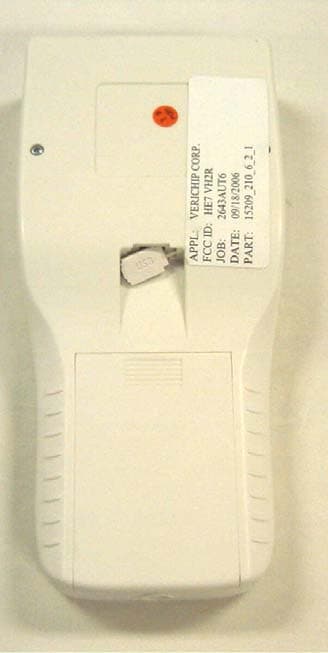
HE7VH2R
Oct 18, 2006VERICHIP H2 READER
Equipment Class
DXX - Part 15 Low Power Communication Device Transmitter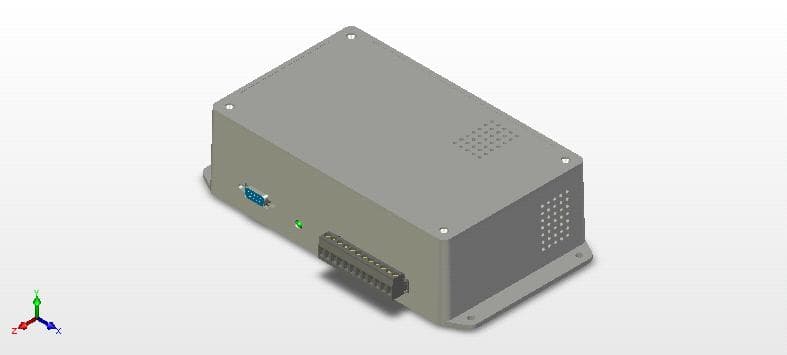
HE7VACR
May 21, 2006VERIGUARRD ACCESS CONTROL READER
Equipment Class
DXX - Part 15 Low Power Communication Device Transmitter
HE7PCR
Apr 06, 2005Receiver
Equipment Class
CYY - Communications Receiver used w/Pt 15 Transmitter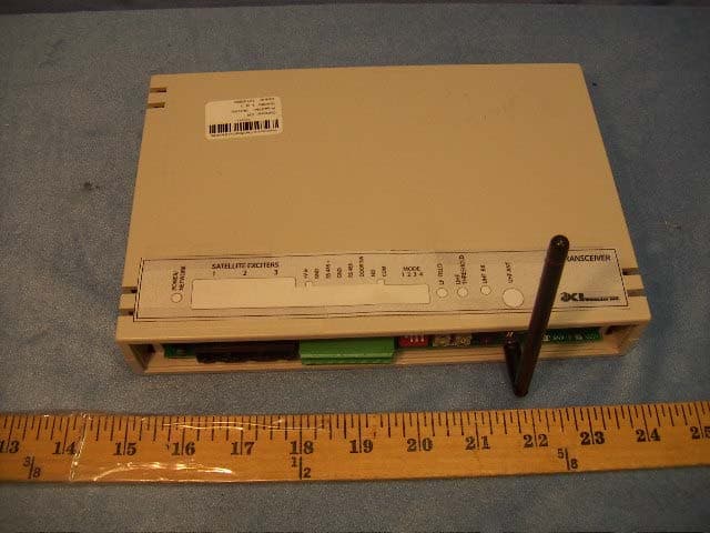
HE7EAC
Feb 07, 2005Transceiver
Equipment Class
DCD - Part 15 Low Power Transmitter Below 1705 kHz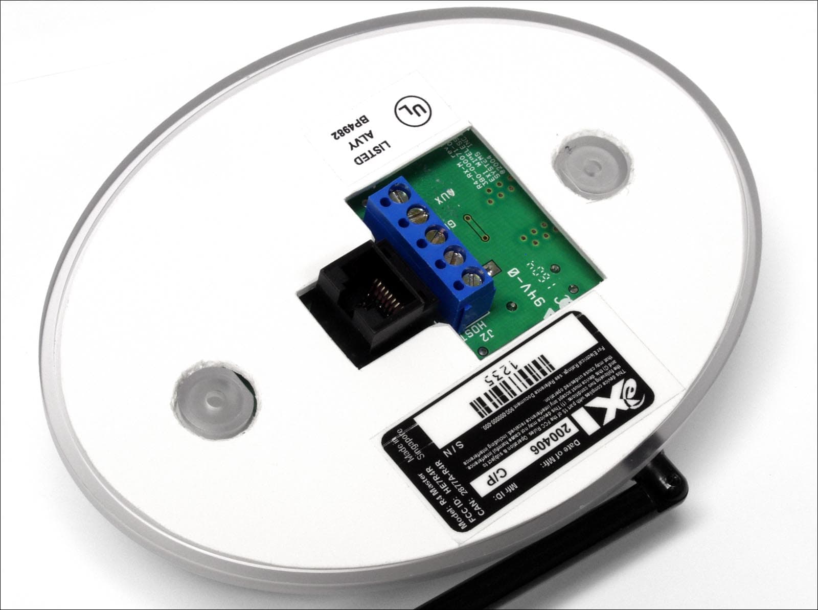
HE7R4R
Oct 13, 2004Communications Receiver
Equipment Class
CYY - Communications Receiver used w/Pt 15 Transmitter