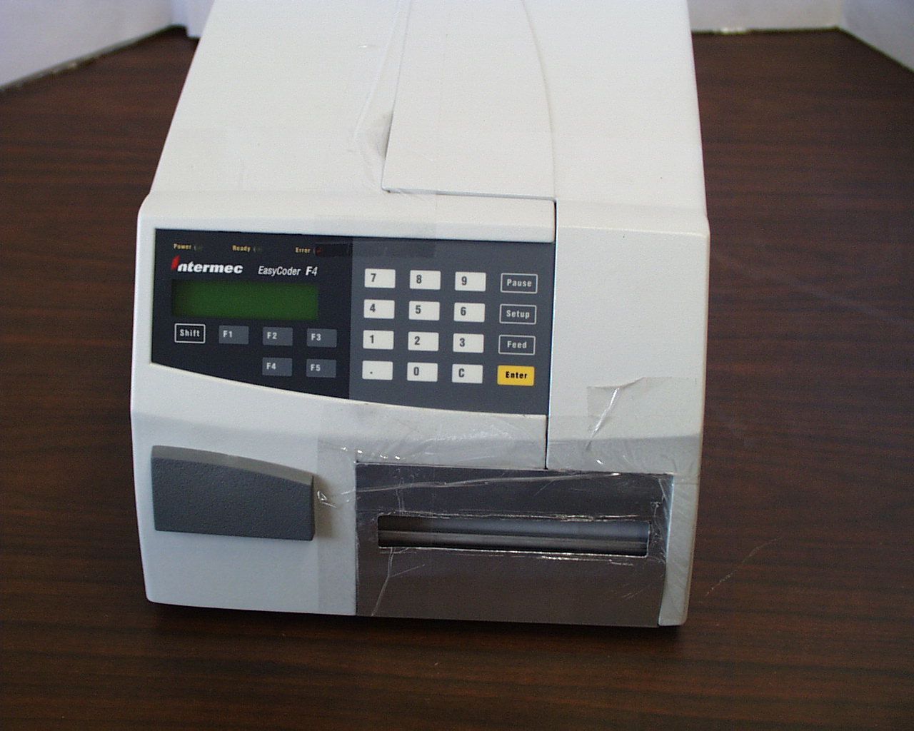
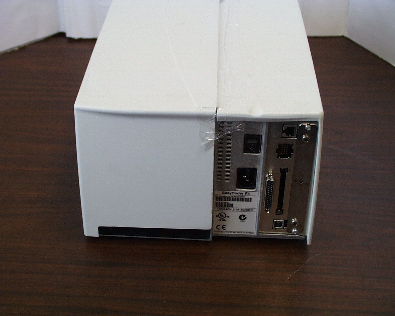
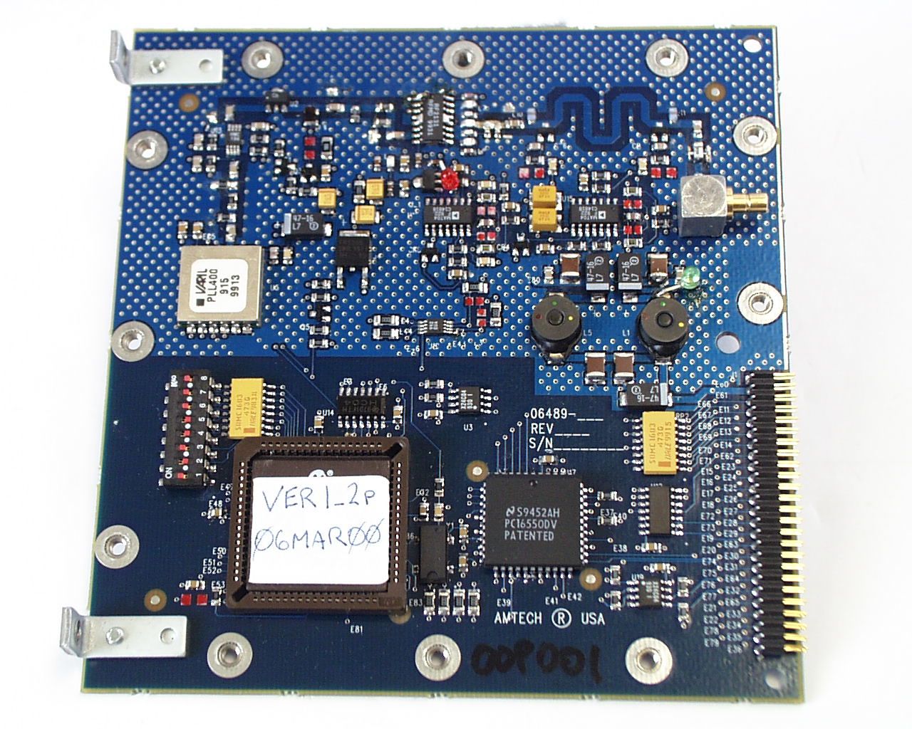
HN2-F4-915-LPRFID Bar Code Printer
Intermec Technologies Corporation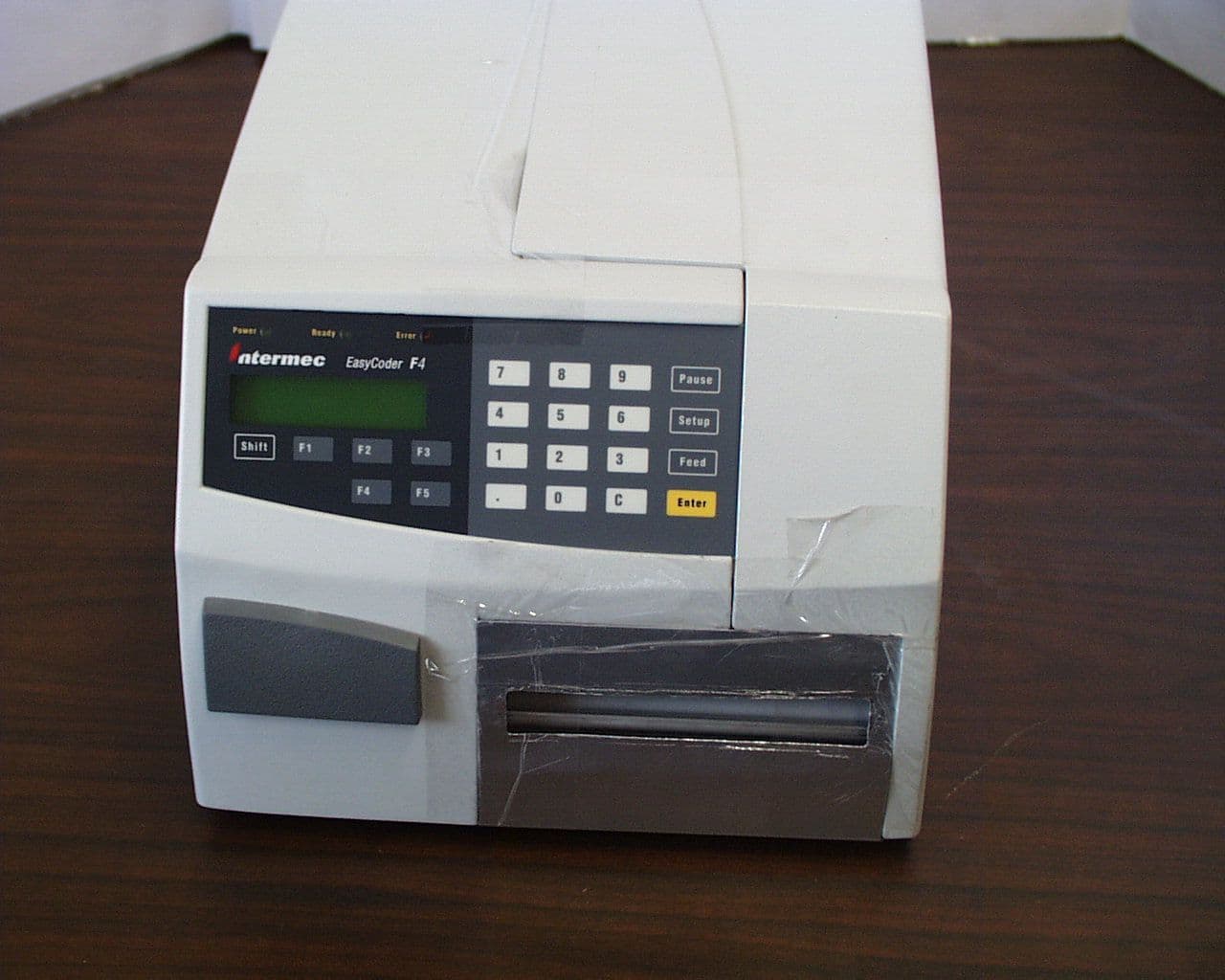
Click to zoom
Application Details
- Equipment Class
- DSS - Part 15 Spread Spectrum Transmitter
- Date of Grant
- Jun 18, 2000
- Application Purpose
- Original Equipment
- Date of Application
- May 16, 2000
- Equipment Note
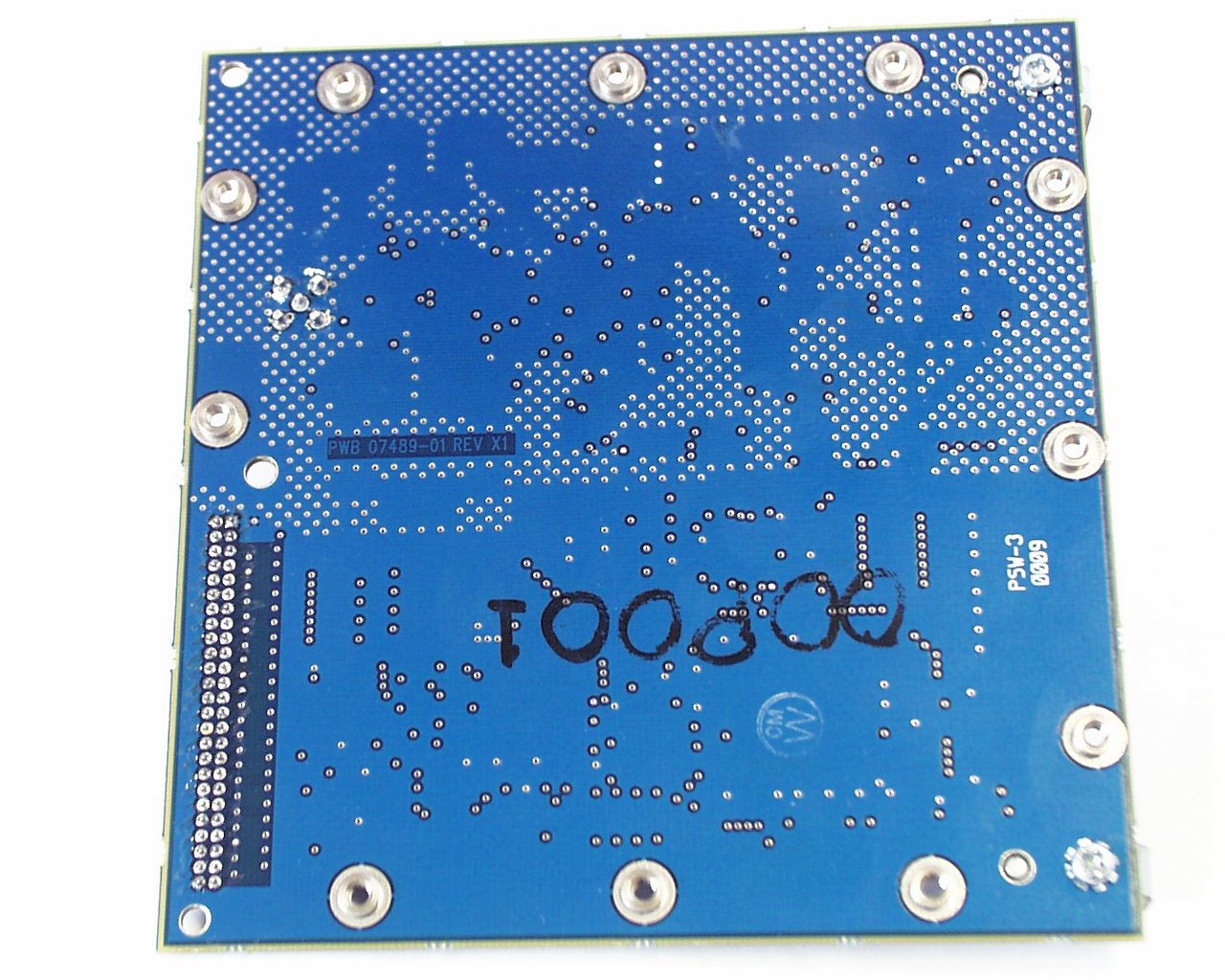
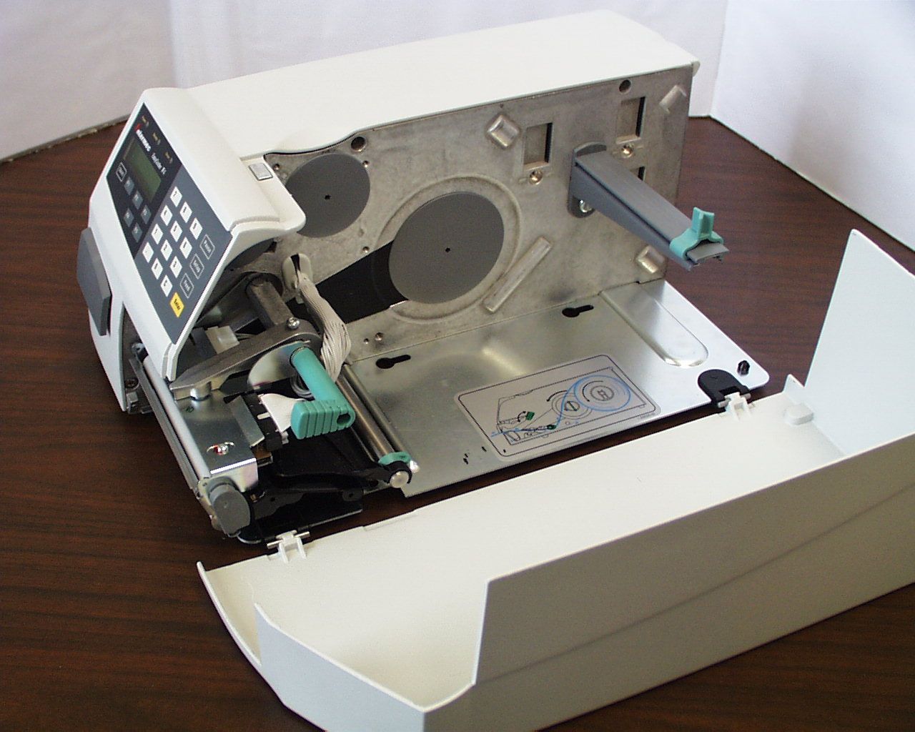
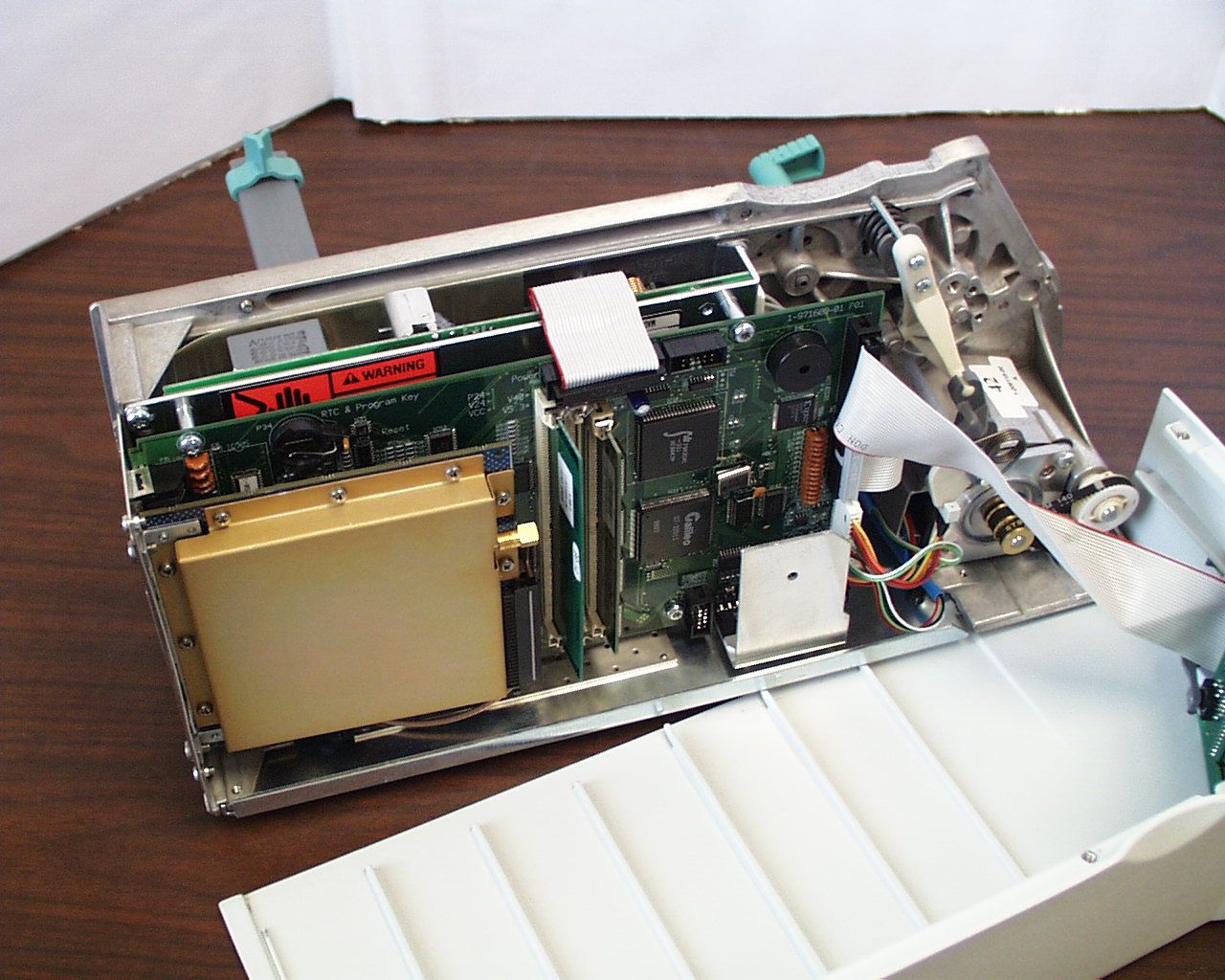
- RFID Bar Code Printer
- Frequency Range
- 902.60000000 - 927.40000000
- Country
- United States
Documents & Files
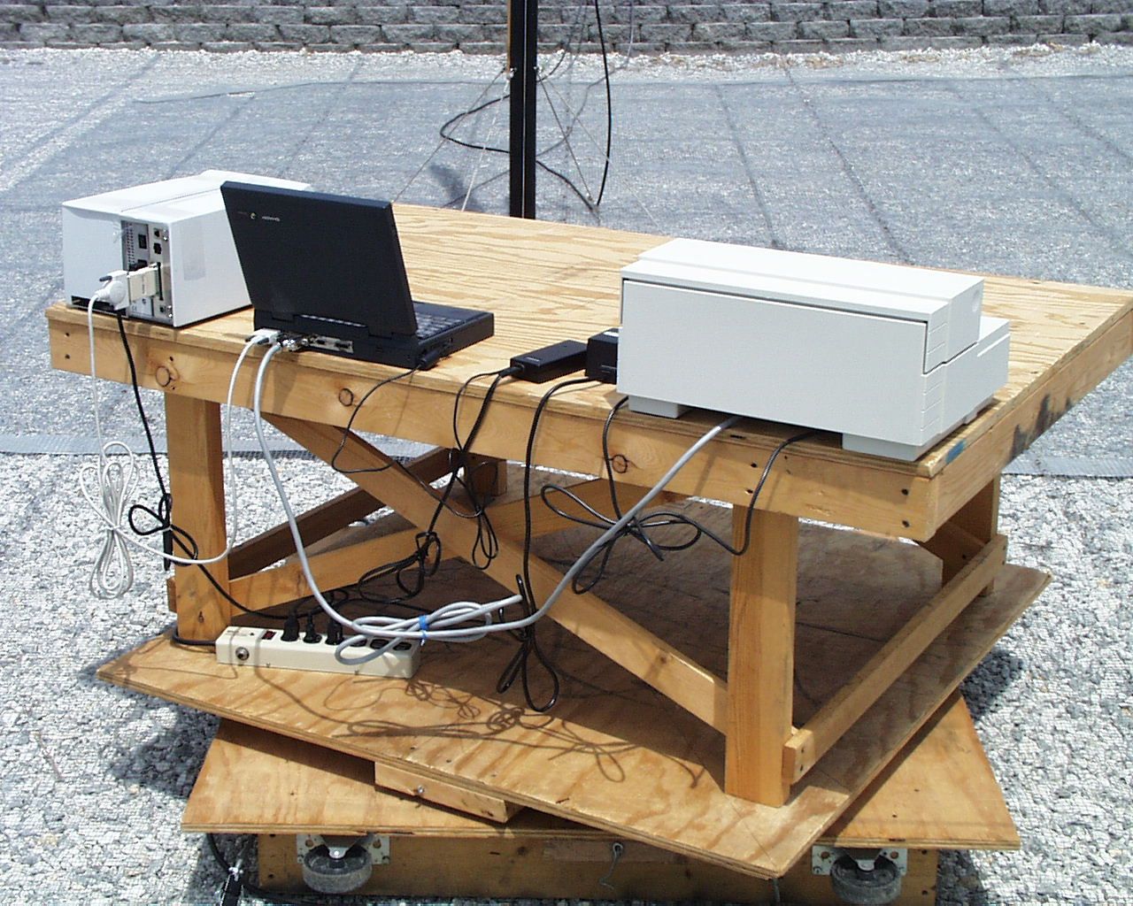
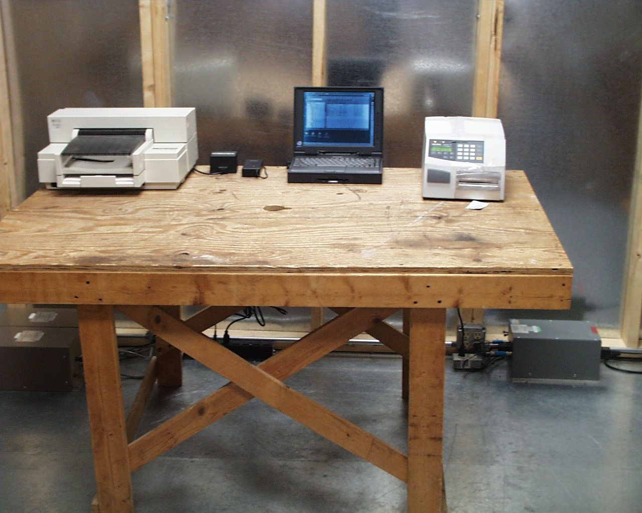
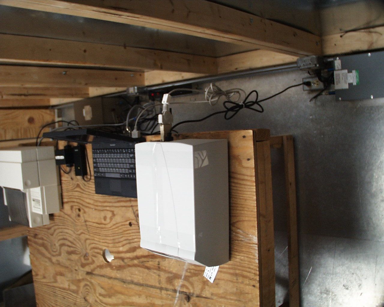
Document Text
Text extracted from the exhibit documents filed with the FCC. Open a document above to read the original.
Users Manual
EasyCoder F4 Bar Code Label Printer Installation & Operation P/N 1-960467-01 Edition 2 March 2000 Intermec EasyCoder F4 – Installation & Operation Ed. 2 1 Preface Preface Table of Contents .................................................................................1 Copyright Information ........................................................................4 Trademarks ..........................................................................................4 FCC Notice (U.S.A.) ...........................................................................5 DOC Notice (Canada).........................................................................5 GS Notice (Germany) .........................................................................5 EU Standard EN 55022 (The European Union) ...............................5 Declaration of Conformity (CE) ........................................................6 1. Introduction Introduction..........................................................................................7 Safety Requirements ...........................................................................8 Product Labelling ................................................................................8 2. Print a Label Introduction..........................................................................................9 Intermec Fingerprint .........................................................................12 Intermec Direct Protocol ..................................................................15 3. Installation Unpacking ..........................................................................................16 Front View ......................................................................................... 17 Rear View ..........................................................................................18 Media Compartment .........................................................................19 Print Mechanism ...............................................................................22 Connections .......................................................................................23 • Power .............................................................................................23 • Computer.......................................................................................23 Controls and Indicators .................................................................... 24 • Control Lamps ............................................................................. 24 • Display.......................................................................................... 24 • Keyboard ...................................................................................... 24 • Beeper ...........................................................................................25 4. Starting Up Startup Files .......................................................................................26 Electronic Keys..................................................................................26 Memory Card ....................................................................................27 Power On............................................................................................27 Display Messages at Startup .............................................................28 EasyCoder F4 Installation & Operation Edition 2, March 2000 Part No. 1-960467-01 Contents Intermec EasyCoder F4 – Installation & Operation Ed. 22 Preface Contents, cont'd. 5. Paper Load Tear-Off..............................................................................................29 Tear-Off with Quick-Load ................................................................33 Peel-Off ..............................................................................................35 External Supply .................................................................................39 6. Setting Up the Printer Description ........................................................................................ 40 Default Setup ..................................................................................... 41 Setup Parameters:..............................................................................42 • Serial Communication: ................................................................42 - Baudrate ......................................................................................42 - Character Length .......................................................................43 - Parity ...........................................................................................43 - Stop Bits ......................................................................................43 - Flow Control...............................................................................43 - New Line ................................................................................... 44 - Receive Buffer ........................................................................... 44 - Transmit Buffer ......................................................................... 44 • Net Communication .....................................................................45 - New Line ....................................................................................45 • Feed Adjust: ..................................................................................45 - Startadjust ...................................................................................45 - Stopadjust....................................................................................45 • Media: ...........................................................................................46 - Media Size ..................................................................................46 - Media Type .................................................................................48 - Paper Type ....................…
Text truncated - open the document above for the full version.
Users Manual
Intermec EasyCoder F4 – Installation & Operation Ed. 2 37 Chapter 5 Paper Load Peel-Off, cont'd. Thread the backing paper around the tear-off edge and back under the print mechanism and guide shaft. Insert the end of the backing paper under the lip of the rewinder, then rotate the rewinder counter-clockwise a few turns. 7 8 This diagram shows the path of the label web. 910 Turn the printhead lift knob counter-clockwise to lower the printhead Intermec EasyCoder F4 – Installation & Operation Ed. 238 Chapter 5 Paper Load Peel-Off, cont'd. Adjust the position of the green paper guide so the paper is guided with a minimum of play. 1112 Close the side door. 13 Adjust the paper feed by pressing the Feed key. Intermec EasyCoder F4 – Installation & Operation Ed. 2 39 Chapter 5 Paper Load External Supply This diagram shows the path of the paper web from an external supply. In case of the standard paper guide ring, it is recommended to turn it to vertical position for better guiding of the web. The EasyCoder F4 can print on labels, tickets, tags, and paper strip in various forms. This chapter describes the case the paper supply is placed behind the printer, usually in the form of fan-folded tickets and tags. External supply can be used in connection with tear-off operation – preferably with Quick-Load. External supply can be used with both short and long side doors and there is no need to remove the paper roll hanger. When using an external paper supply, take care to protect the paper from dust, dirt or other foreign particles, that can impair the printout quality or cause unnecessary wear to the printhead. Direct thermal paper is more or less sensitive to heat, direct sunlight, moisture, oil, plasticizers, fat, and other substances, depending on brand and quality and should be protected accordingly. 1 Intermec EasyCoder F4 – Installation & Operation Ed. 240 Chapter 6 Setting Up the Printer Description The setup is used to control the printer in regard of serial com- munication, paper feed and print speed, and to specify which type of paper is loaded in the printer. Check the list of default setup values below to see if the printer's setup matches your requirements. If not, you will have to change the setup, which can be done manually via the printer's built-in keyboard, remotely from the host computer, or by reading a bar code containing setup data with the optional EasySet bar code wand. The setup may also be changed, partially or completely, by certain application programs. • In the Setup Mode: - Press the <Setup> key on the printer's built-in keyboard to enter the Setup Mode. - Select the Setup option in Intermec Shell to enter the Setup Mode. - Execute the Intermec Fingerprint SETUP instruction to enter the Setup Mode. See chapter 7 “Setup Mode” in this manual. • In Intermec Shell: - Use Terminal Setup option to change the setup remotely from the host. Note that Intermec Shell automatically sets up the printer in regard of communication when an application is selected. See chapter 8 “Intermec Shell” in this manual. • In Intermec Fingerprint: - Use Setup strings to change individual setup parameters remotely from the host. - Use Setup fi les to create sets of setup parameters remotely from the host. See SETUP statement in the Intermec Fingerprint 7.xx Reference Manual. • In the Intermec Direct Protocol: - Use Setup strings to change individual setup parameters remotely from the host. See Intermec Direct Protocol 7.xx Programmer's Guide. • Using the EasySet Bar Code Wand: - Read a Code 128 bar code containing the setup parameter id. and the desired value or choice. See Appendix 4. Intermec EasyCoder F4 – Installation & Operation Ed. 2 41 Chapter 6 Setting Up the Printer Default Setup The printer is by default set up according to the list below: Ser-Com "uart1:" Baudrate: 9600 bps Character length: 8 bits Parity: None Stop bits: 1 bit RTS/CTS: Disable ENQ/ACK: Disable XON / XOF F, data to host: Disable XON/XOFF, data from host: Disable New line: CR/LF Receive buffer: 300 bytes Transmit buffer: 300 bytes Feedadjust : Startadjust: 0 Stopadjust: 0 Media: X-sta r t: 24 Width: 832 Length: 1200 Media Type: Label (w Gaps) Label Constant: 85 Label Factor: 40 Contrast: ±0% Print Defi nes: Print speed: 100 mm/sec. The printer's current setup values can be read from the display by browsing through the Setup Mode, or from the host by browsing through the Terminal Setup of Intermec Shell. You can list the printer's current setup values by printing test label #5 in the Setup Mode or using Intermec Shell. The current setup values can be returned to the host by means of a SETUP WRITE "uart1:" statement (see Intermec Fingerprint 7.xx Reference Manual). Intermec EasyCoder F4 – Installation & Operation Ed. 242 Chapter 6 Setting Up the Printer Setup Parameters Serial Communication • Baudrate • Character Length • Parity • Stop Bits • Flow Control • New Line • Receive Buffer • Transmit Buffer The serial communication setup controls the communication between the printer and the connected computer or other devices on the standard serial channel "uart1:" and the optional serial channels "uart2:" and "uart3:". The latter channels require an optional interface board to be fi tted. The printer's fi rmware detects if an optional interface board is fi tted and presents additional sets of communication setup menus depending on type of communication (refer to diagrams #3 – 5 in chapter 7 “Setup Mode”). The serial communication setup has no consequence whatsoever for parallel communication or for the IN and OUT ports on the optional Industrial Interface Board. For the serial communication channel "uart1", the following parameters can be set. Make sure they match the setup of the connected device or vice versa. If the setup of the printer and the setup of the host do not match, the response from the printer to host will be garbled. Baudrate The baudrate is the transmission speed in bits per second. There are 10 options: • 300 • 6…
Text truncated - open the document above for the full version.
Users Manual
Intermec EasyCoder F4 – Installation & Operation Ed. 278 Chapter 11 Maintenance Printhead Cleaning, cont'd. Wait for approx. 30 seconds to allow the cleaning fl uid to dissolve the residue. Insert most of the cleaning card under the printhead (1). Close the printhead (2). 9 Allow the cleaned parts to dry before loading any paper. Pull out the cleaning card. If necessary, repeat the process with a new cleaning card. 87 10 Intermec EasyCoder F4 – Installation & Operation Ed. 2 79 Chapter 11 Maintenance 1 External Cleaning Always remove the power cord before cleaning! Wipe external surfaces with a soft cloth slightly moistened with water or a mild detergent. 3 Never use any sharp tools for removing stuck labels. The printhead and rollers are delicate. Never spray the printer. Protect it from water when cleaning the premises. 2 4 Intermec EasyCoder F4 – Installation & Operation Ed. 280 Chapter 11 Maintenance Cleaning the Paper Guides Both parts of the label stop sensor, which controls the paper feed, are covered by plastic guides. The guides are provided with seemingly non-transparent areas, through which the light between the two parts of the label stop sensor is transmitted. These areas (indicated by a shade of grey in illustration #2 below) must be kept clean from dust, stuck labels, and adhesive residue. If the printer starts to feeed our labels in an unexpected way. lift the upper guide – as described below – and check for anything that may block the beam of light (dust, stuck labels, adhesive residue etc.). If necessary, clean the guides using a cleaning card or a soft cloth soaked with isopropyl alcohol. Do not use any other the of chemical. Be careful not to scratch the guides. Caution! Isopropyl alcohol [(CH 3 ) 2 CHOH; CAS 67- 63- 0] is a highly fl ammable, moderately toxic and mildly irritating substance. Lift the inner part of the upper guide and pull it outwards,disengaging it from the lower guide. Take care not to damage the cable. Tilt the upper guide upwards and clean the areas marked with grey. After cleaning, reas- semble in reverse order. 12 Intermec EasyCoder F4 – Installation & Operation Ed. 2 81 Chapter 11 Maintenance Printhead Replacement The printhead is subject to wear both from the direct thermal paper and from the rapid heating and cooling process during printing. Thus, the printhead will require periodical replacement. Time between printhead replacements depends on the print images, the type of paper in use, the amount of energy to the printhead, and several other factors. Note! While replacing the printhead, the power should be switched off. Open the side door. Turn the printhead lift knob clockwise to lift the printhead. 12 Intermec EasyCoder F4 – Installation & Operation Ed. 282 Chapter 11 Maintenance Printhead Replacement, cont'd. Pull the printhead bracket away from the magnet in the pressure arm. 3 4 Disconnect the printhead bracket from the print mechanism – as indicated by the arrows – and pull out the printhead as far as the cables allow. 6 5 Disconnect the cables from the printhead. Note the snap-lock on the inner connector. Pull at the connectors – not the cables! Remove the paper, if any. Snap-lock Intermec EasyCoder F4 – Installation & Operation Ed. 2 83 Chapter 11 Maintenance Printhead Replacement, cont'd. Connect the two cables to the replacement printhead. Put back the printhead in reserse order and check that the printhead cables run freely. 9 Load a new supply of paper as described ear- lier in this manual. Close the printhead so the magnet engages the printhead bracket. 87 10 Intermec EasyCoder F4 – Installation & Operation Ed. 284 Chapter 12 Narrow Labels Adjustment The printer is factory-adjusted for full size paper width. When using paper less than full width, it is recommended to adjust the pressure arm so it becomes centred on the paper. Thereby, an even pressure across the paper is obtained. A poorly adjusted pressure arm may be detected by a weaker printout on the inner part of a less than full width paper. Similarly, when reverting to a wider paper, the arm should be adjusted, or the printout on the outer part of the paper could be weak. To adjust the pressure arm, proceed as follows: • Loosen the nut that holds the pressure arm. Move the arm inwards or outwards until the arrow on the tip of the arm becomes centre-aligned with the paper web. While moving the arm, push at the part where the nut is situated, not at the tip. If the arm is hard to move, lift the printhead and pull the printhead bracket free from the magnet in the arm. • After having centred the arm, lock it by tightening the nut. Adjustments Centre of Paper Pressure Arm Nut Intermec EasyCoder F4 – Installation & Operation Ed. 2 85 Chapter 12 Adjustments Label Stop Sensor Position The label stop/black mark sensor (LSS) is a photoelectric sensor that controls the printer's paper feed by detecting gaps between labels, slots in paper strip, or black marks, depending on the printer's setup in regard of media type (see chapter 6 “Setting Up the Printer”). A prerequisite is obviously that the LSS is aligned with the slots or black marks. Thus, the LSS can be moved laterally between 5 fi xed positions. There is one sensor on top of the upper paper guide and underneath the bottom of the print unit. These two guides must be set individually to the same position. Push them inwards as far as they go and then pull them out – one at the time – while counting the clicks from the snap-locks. The various detection points of the sensor in relation to the inner edge of the paper are as follows: One click out 3 mm .118" Two clicks out 8 mm .315" Three clicks out 12 mm .472" Four clicks out 16 mm .639" Five clicks out 20 mm .787" If using irregularly shaped labels, align the LSS with the front tips of the labels Upper part of LSS Print Unit (printhead and headlift shaft omitted for improved visibility) One Diode + One Sensor Lower part of LSS One Sensor Intermec EasyCoder F4 – Installation & Ope…
Text truncated - open the document above for the full version.
Cover Letter(s)
Inte rme c Te chnologie s Corporation Amtech Systems Division 8600 Jefferson St. NE Albuquerque, NM 87113 Phone: (505) 856-8054 Fax: (505) 857-0715 May 17, 2000 E- ma il: wma ys @ a s c tmd . c o m Federal Communications Commission Equipment Authorization Division 7435 Oakland Mills Road Columbia, MD 21046 RE:Request for Confidential Treatment FCC ID No: HN2-F4-915-LP Dear Sirs: Amtech Systems Division of Intermec Technologies Corp. requests that the materials in the Block Diagram, Schematics, and Operational Description be withheld from public disclosure in accordance with Section 0.459 of the Commission’s Rules, 47 C.F.R. § 0.459 (1998), following grant of the application. In support of this request, Intermec submits the following: (1) identification of the specific information for which confidential treatment is sought: The materials set forth in the Operational Description, Block Diagram, Parts List, and Schematics, which are segregated from the non-confidential exhibits of the application, are those for which confidentiality is sought. (2) identification of the Commission proceeding in which the information was submitted or a description of the circumstances giving rise to the submission: The proceeding is that involving the application for equipment authorization (certification) under FCC ID No.: HN2-F4-915-LP (3) explanation of the degree to which the information is commercial or financial, or contains a trade se cre t or is privile ge d: This material includes detailed theory of operation, circuit diagrams (schematics and blocks), and parts list. As such, this material is treated as highly confidential business information (4) explanation of the degree to which the information concerns a service that is subject to competition: The material for w hich confidentiality is sought is employed in the design and manufacture of Radio Frequency Identification (RFID) transmitting equipment that is offered on a highly competitive basis. Customers for this equipment have a variety of competing sources of supply. (5) e xplanation of how disclosure of the information could re sult in substantial compe titive harm: Disclosure would, in effect, give away the fruits of the labors of Intermec’s engineering personnel, who have designed the equipment and the manufacturing processes. Disclosure would also offer competitors additional unwarranted insight into the state of product development thereby allowing such competitors an advantage that would not be available to Intermec. page 2 (6) ide ntification of any me asure s take n by the submitting party to pre ve nt unauthoriz e d disclosure : The information for w hich confidential treatment is sought is kept confidential by Intermec and not made available to third parties except pursuant to non-disclosure agreements. (7) identification of whether the information is available to the public and the extent of any previous disclosure of the information to third partie s: To the knowledge of those preparing this application, the information has not been disclosed publicly heretofore. While the general theory of operation of this non-multilateration equipment has been the subject of numerous disclosures in industry and standards groups as well as in rule making proceedings at the FCC, the protection sought is narrow ly draw n and pertains to certain specific implementations of modulated backscatter radio technology. (8) justification of the period during which the submitting party asserts that material should not be available for public disclosure : This material should not be disclosed for at least 25 years. While improvements in design are made relatively frequently, disclosure of the design information would lead to insights into both designs and manufacturing techniques and could have an adverse competitive effect for many years to come. This equipment is designed for commercial, industrial, and governmental transportation applications. As such, unlike most consumer equipment, it is expected to be used for more than a decade in some cases. Moreover, this equipment will be used in revenue collection (e.g. toll collections) and secure access control applications (e.g. freight handling facilities). As such, it is important that its design not be made available to unauthorized persons who might attempt to use knowledge of the design to compromise the applications for which the equipment will be employed. (9) any other information that the party seeking confidential treatment believes may be useful in assessing whether its request for confidentiality should be granted: See item 8 above. Note that the equipment for which approval is being sought will be employed in applications that inherently carry a premium on security. Respectfully, Wesley M. Mays Engineering Manager Amtech Systems Division Intermec Technologies Corporation
Parts List/Tune Up Info
Inte rme c Te chnologie s Corporation Amtech Systems Division 8600 Jefferson St. NE Albuquerque, NM 87113 Phone: (505) 856-8054 Fax: (505) 857-0715 May 17, 2000 E- ma il: wma ys @ a s c tmd . c o m Federal Communications Commission Equipment Authorization Division 7435 Oakland Mills Road Columbia, MD 21046 RE:Part Lists/ Tune Up Info FCC ID No: HN2-F4-915-LP Dear Sirs: Pursuant to section 2.983(d)(6), the list of active devices and description of the function of each semiconductor and other active circuit elements are included as a portion of the operational description and are included under separate cover in the exhibit titled “Operational Description”. Pursuant to section 2.983(d)(9), the RFID printer module has no user adjustable controls. The device has no provisions for any type of alignment and therefore requires no tuning. The power level is set at the factory at final test is not adjustable. Respectfully, Wesley M. Mays Engineering Manager Amtech Systems Division Intermec Technologies Corporation
Test Report
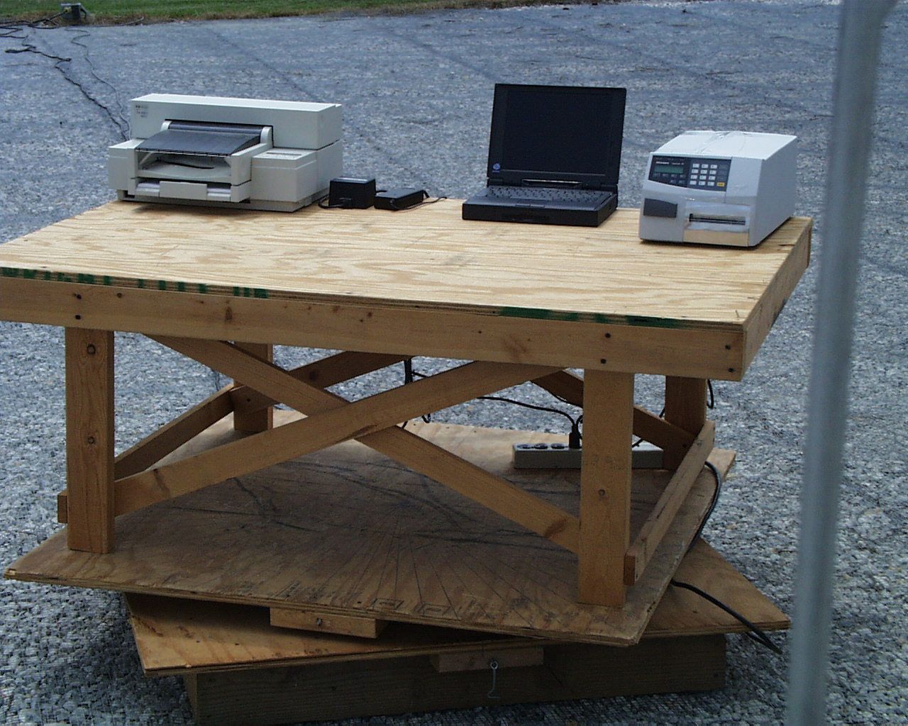
TEST REPORT For APPLICATION of CERTIFICATION For INTERMEC TECHNOLOGIES CORPORATION 6001 36th Avenue West Everett, WA 98203-9280 Phone: (505) 856-8054 Wes Mays, Manager of Microwave Designs MODEL: F4 915 Printer Reader Frequency 902.6 – 927.4 MHz FCC ID: HN2-F4-915-LP Test Date:May 8, 2000 Certification Date: May 8, 2000 Certifying Engineer: Scot D. Rogers ROGERS LABS, INC. 4405 West 259 th Terrace Louisburg, KS 66053 Phone: (913) 837-3214 FAX: (913) 837-3214 This report shall not be reproduced except in full, without the written approval of the laboratory. This report must not be used by the client to claim product endorsement by NVLAP or any agency of the U.S. Government. ROGERS LABS, INC. 4405 West 259 th Terrace Louisburg, KS 66053 Phone / Fax (913) 837-3214 NVLAP Accredited LaboratoryNVLAP Lab Code: 200087-0 ROGERS LABS, INC.INTERMEC TECHNOLOGIES CORPORATION 4405 W. 259th TerraceMODEL: F4 915 Printer Reader Louisburg, KS 66053Test #: 000508FCCID#: HN2-F4-915-LP Phone/Fax: (913) 837-3214Test to: FCC Parts 2 and 15c 15.247Page 2 of 35 CERTIFICATION\F4915LP 05/12/2000 TABLE OF CONTENTS FORWARD:.....................................................................................................................3 1)APPLICABLE STANDARDS & TEST PROCEDURES............................................3 2)APPLICATION FOR CERTIFICATION PER 2.1033(B)............................................4 3)EQUIPMENT TESTED..............................................................................................5 4)EQUIPMENT FUNCTION AND TESTING PROCEDURES......................................5 5)EQUIPMENT AND CABLE CONFIGURATIONS......................................................5 Conducted Emission Test Procedure................................................................................................................5 Radiated Emission Test Procedure...................................................................................................................6 6)LIST OF TEST EQUIPMENT....................................................................................6 7)UNITS OF MEASUREMENTS..................................................................................7 8)TEST SITE LOCATIONS..........................................................................................7 9)SUBPART B – UNINTENTIONAL RADIATORS......................................................8 Conducted EMI...................................................................................................................................................8 Radiated EMI....................................................................................................................................................10 Data: Conducted (8 Highest Emissions):..........................................................................................................13 Data: EUT and System Radiated Emissions (8 Highest) :................................................................................13 Summary of Results for Conducted Emissions:................................................................................................13 Summary of Results for Radiated Emissions:...................................................................................................14 Statement of Modifications:..............................................................................................................................14 10)SUBPART C - INTENTIONAL RADIATORS.........................................................14 15.203 Antenna Requirements........................................................................................................................14 Restricted Bands of Operation Per 15.205.....................................................................................................14 Data 15.205:......................................................................................................................................................15 15.209 Radiated Emissions Limits; General Requirements..........................................................................16 Radiated EMI....................................................................................................................................................16 Data 15.209:......................................................................................................................................................17 Summary of Results for Radiated Emissions:...................................................................................................17 15.247 Operation in the Band 902-928 MHz.................................................................................................17 Summary of Results for Radiated Emissions of Intentional Radiator:..............................................................24 Statement of Modifications:..............................................................................................................................24 NVLAP Accredited LaboratoryNVLAP Lab Code: 200087-0 ROGERS LABS, INC.INTERMEC TECHNOLOGIES CORPORATION 4405 W. 259th TerraceMODEL: F4 915 Printer Reader Louisburg, KS 66053Test #: 000508FCCID#: HN2-F4-915-LP Phone/Fax: (913) 837-3214Test to: FCC Parts 2 and 15c 15.247Page 3 of 35 CERTIFICATION\F4915LP 05/12/2000 FORWARD: The following is submitted for consideration in obtaining a Grant of Certification for low power intentional radiators operated under CFR 47, paragraph 15.247. Name of Applicant: INTERMEC TECHNOLOGIES CORPORATION 6001 36th Avenue West Everett, WA 98203-9280 Model: F4 915 Printer Reader FCC I.D.: HN2-F4-915-LP Frequency Range: 902.6 MHz to 927.4 MHz Operating Power: 1 Watt 1)Applicable Standards & Test Procedures a)In accordance with the Federal Communications Code of Federal Regulations, dated October 1, 1999, Part 2, Subpart J, Paragraphs 2.907, 2.911, 2.913, 2.925, 2.926, 2.1031 through 2.1057, Part 15C Paragraph 15.…
Text truncated - open the document above for the full version.
Contact Information
Applicant
Brian Rudick(VP & GC, Honeywell Scanning & Mobility)
Technical Contact
Amtech Systems DivisionWesley M Mays
[email protected]505-856-8054
8600 Jefferson Street, NE · Albuquerque, New Mexico · United States
Non-Technical Contact
Amtech Systems DivisionWesley M Mays
[email protected]505-856-8054
Test Firm
Rogers Labs, Inc.Scot Rogers
Technical Specifications
| # | Rule Parts | Frequency Range | Power Output | Tolerance |
|---|---|---|---|---|
| 1 | 15C | 902.6 MHz - 927.4 MHz | 500.00 mW | 100.0000000000 ppm |
Other Applications from Intermec Technologies Corporation

HN2-BTM311
Nov 23, 2004BTM311
Equipment Class
DTS - Digital Transmission System
HN2-802CF13E
Nov 07, 2004EasyLAN
Equipment Class
DTS - Digital Transmission System
HN2WAMIG2
Nov 18, 2003802MIG2
Equipment Class
DTS - Digital Transmission System
HN2SB555-2
Sep 04, 2003SB555 Radio in 700C
Equipment Class
PCE - PCS Licensed Transmitter held to ear
HN22011B-2
Jul 28, 20032011B Radio in 700C
Equipment Class
DTS - Digital Transmission System