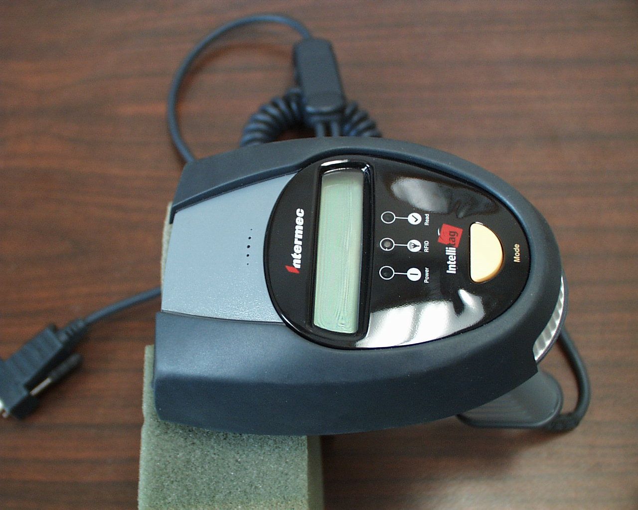
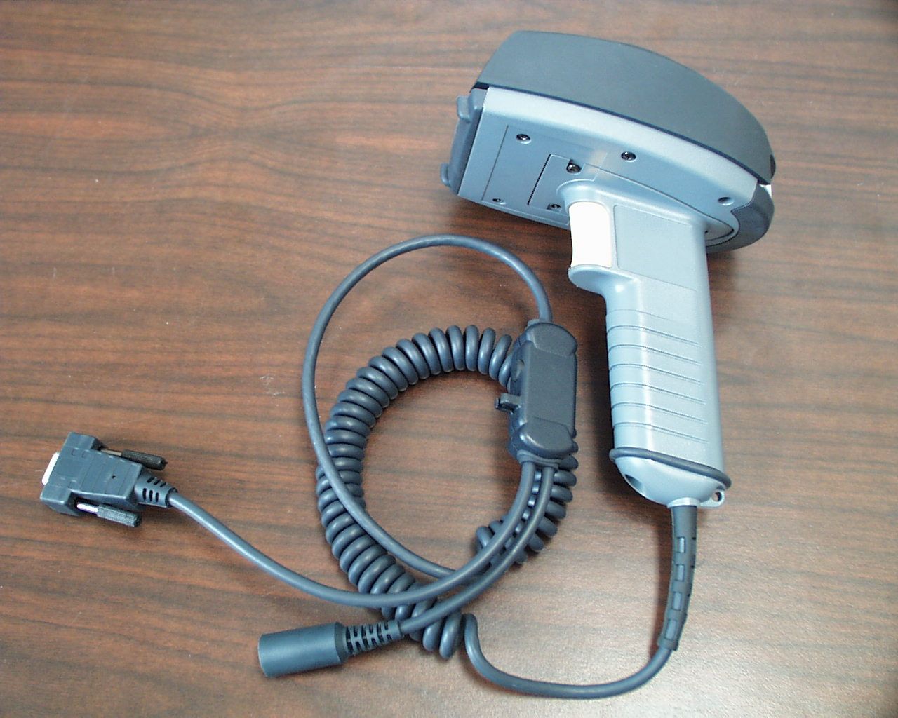
HN21555-900Hand Held Reader
Intermec Technologies Corporation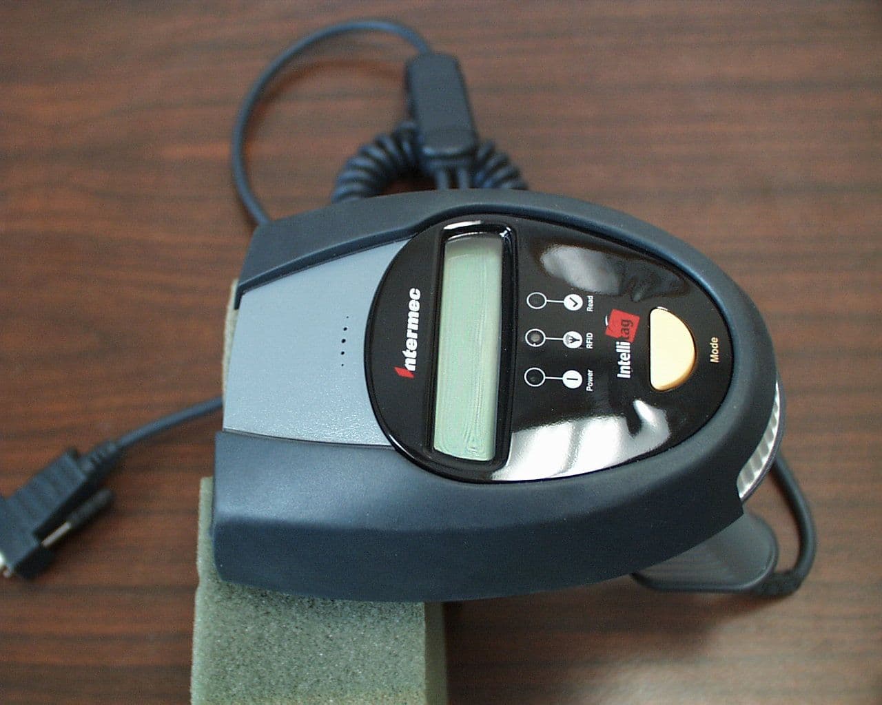
Click to zoom
Application Details
- Equipment Class
- DSS - Part 15 Spread Spectrum Transmitter
- Date of Grant
- Jan 25, 2001
- Application Purpose
- Original Equipment
- Date of Application
- Sep 06, 2000
- Equipment Note
- Hand Held Reader
- Frequency Range
- 902.60000000 - 927.40000000
- Country
- United States
Documents & Files
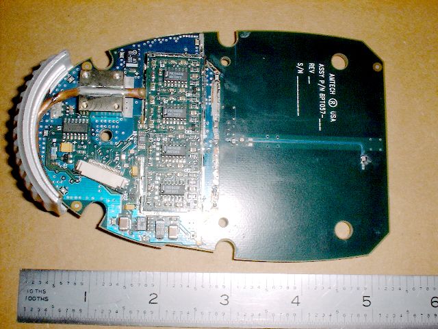
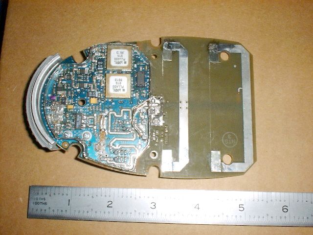
Document Text
Text extracted from the exhibit documents filed with the FCC. Open a document above to read the original.
Users Manual
P/N x-xxxx49-01 Sabre 1555 Laser Scanner & RFID Reader/Programmer Getting Started Guide Anleitung für Einsteiger Guia de IniciaçãoGuide de Démarrage Guida IntroduttivaGuía de Iniciación 2 Introduction Use this Getting Started Guide to set up the Sabre 1555 laser scanner and RFID reader/ programmer for most terminal connections and symbologies. If necessary, use the EasySet setup software or Installation Manual for additional configuration possibilities and terminal connections. Basic setup Configuración básica Configuration de base Grundkonfiguration Configurazione di base Getting Started Guide EasySet Full setup Configuración completa Configuration complète Vollständige Konfiguration Configurazione completa Configuração completa EasySet setup software (on the CD-ROM or to order) Installation Manual Operating Uso Utilisation Betrieb Utilizzazione Operator’s Guide Interactive Programming (need translations to other languages) Interactive Programming Guide 3 Connect scanner cable (standard version shown) Scanner cable depends on your terminal Cables Accessories 4 RFID reader/programmer reading distance RFID reader/programmer operation Sabre 1555 2450 MHz Sabre 1555 915 MHz 2.5 cm - 200 cm (1" - 80") 1 cm - 60 cm (0.4" - 24") "beep" 5 Scanner reading distance Scanner operation "beep" Sabre 1555 Standard Range Sabre 1555 Long Range 6 cm - 34 cm (2.5" - 13.5") 28 cm - 100 cm (11" - 39") 6 Ê Ë Ì Í Î RS-232 C Connect cable Scanner power ON Direct RS-232 C cable P/N 3-604032-00 System power OFF System power ON Select standard RS-232 C (PC serial port compatible) 9600 baud, 7 data bits, even parity, 2 stop bits postamble = carriage return + line feed Ê Ë Ì Í Î 7 Customize parameters (optional) (*) = default value Ï 9600 baud (*) 19200 baud 7 data bits (*) 8 data bits No parity Postamble = Carriage Return Postamble = none Even parity (*) Odd parity Postamble = Carriage Return + Line Feed (*) 8 Ê Ë Ì Í Î RS-232 TTL Connect cable Scanner power ON System power OFF System power ON Select RS-232 TTL 9600 baud, 7 data bits, even parity, 2 stop bits postamble = carriage return + line feed Ê Ë Ì Í Î Direct RS-232 TTL cable P/N x-xxxxxx-xx 9 Customize parameters (optional) (*) = default value Ï 9600 baud (*) 19200 baud 7 data bits (*) 8 data bits No parity Postamble = Carriage Return Postamble = none Even parity (*) Odd parity Postamble = Carriage Return + Line Feed (*) 10 Ê Ë Ì Í Î Universal Serial Bus (USB) Connect cable Scanner power ON Direct USB cable P/N x-xxxxxx-xx System power OFF System power ON Select standard USB (PC serial port compatible) 9600 baud, 7 data bits, even parity, 2 stop bits postamble = carriage return + line feed Ê Ë Ì Í Î 11 Customize parameters (optional) (*) = default value Ï Intermec representative needs to supply USB symbologies when the symbols are available. 12 EAN 13 1234567890128 Code 128 CODE-128 Code 39 CODE-39 UPC-A, UPC-E, EAN-8, EAN-13 (UPC-A -> EAN-13) UPC-A, UPC-E, EAN-8, EAN-13 (UPC-A -> UPC-A) Code 39 Code 128 / EAN 128 Symbology Disable all symbologies Ê Select symbology Ë Test Ì UPC-A 13 EasySet Online setup Reset Connect RS-232 C cable (P/N 3-604032-00) Scanner power ON System power OFF System power ON Start EasySet software Scan EasySet setup code Ê Ë Ì Í Î Ï 14 CAUTION – Use of controls or adjustments or performance of procedures other than those specified herein result in hazardous laser light. VORSICHT – Bei einer anders als hier beschriebenen Verwendung der Bedienelemente oder Veränderungen oder einer anderen Ausführung der Arbeitsabläufe entsteht gefährliches Laserlicht. ATTENTION – L’utilisation de contrôles/commandes ou de réglages ou l’exécution de procédures autres que ceux précisés par le présent document provoquent une lumière laser dangereuse. Laser warnings Fix these warning labels onto the product if they are not already present. The Sabre 1555 has a maximum laser output of 1mW at 630-680 nm and complies with the following safety standards: USA: CDRH - Class II Laser Product (CFR 21 Subpart J) IEC 825-1 EN 60825-1 - Class 2 Laser Product Cole as etiquetas de precaução no equipamento. Un’etichetta di avviso per il laser è da applicare sul prodotto. Collez les étiquettes d’avertissement sur votre produit. Bringen Sie Warnetiketten auf dem Produkt an. Fije la etiqueta de advertencia en el producto. 15 N309 Regulatory statements © 09/00 Intermec Technologies Corporation.1.0EditionEditionAll rights reserved. USA & Canada: This Class B digital apparatus meets all requirements of the Canadian Interference-Causing Equipment Regulations. This device requires a radio license, unless it is used totally inside of a building. (The user must obtain this license.) Cet appareil numérique de la classe B respecte toutes les exigences du Règlement sur le matériel brouilleur du Canada. Cet appareil exige une license radio à moins d’être entièrement installé dans un bâtiment. (L’utilisateur doit obtenir cette license.) This device complies with Part 15 of the FCC Rules and with RSS-210 of Industry Canada. Operation is subject to the following two conditions: (1) this device may not cause harmful interference, and (2) this device must accept any interference received, including interference that may cause undesired operation. This equipment is intended for operation in a commercial environment, in compliance with the requirements for a Class A digital device, pursuant to Part 15 of the FCC Rules, and it must not be used in a residential environment. It generates, uses, and can radiate radio frequency energy. If not installed and used in accordance with the instruction manual, it may cause interference to radio communications. If this equipment causes interference, the user will be required to correct the interference at the user’s own expense. To maintain compliance with the FCC Rules, the input/output (I/O) cables that interconnect between the device and any peripheral (such as a reader) must be as specified by Intermec. Operator Warning: FCC regulations limit expos…
Text truncated - open the document above for the full version.
Users Manual
P/N x-xxxx49-00 Sabre 1555 Laser Scanner & RFID Reader/Programmer Operator’s Guide Bedieneranleitung Guida dell'operatore Guía del Usuario Guia do Utilizador Guide de l'Opérateur 2 RFID reader/programmer reading distance RFID reader/programmer operation Sabre 1555 2450 MHz Sabre 1555 915 MHz 2.5 cm - 200 cm (1" - 80") 1 cm - 60 cm (0.4" - 24") Sabre 1555 915 MHz Sabre 1555 2450 MHz "beep" "beep" 3 Scanner reading distance Scanner operation "beep" Sabre 1555 Standard Range Sabre 1555 Long Range 6 cm - 34 cm (2.5" - 13.5") 28 cm - 100 cm (11" - 39") 4 CAUTION – Use of controls or adjustments or performance of procedures other than those specified herein result in hazardous laser light. VORSICHT – Bei einer anders als hier beschriebenen Verwendung der Bedienelemente oder Veränderungen oder einer anderen Ausführung der Arbeitsabläufe entsteht gefährliches Laserlicht. ATTENTION – L’utilisation de contrôles/commandes ou de réglages ou l’exécution de procédures autres que ceux précisés par le présent document provoquent une lumière laser dangereuse. Laser warnings Fix these warning labels onto the product if they are not already present. The Sabre 1555 has a maximum laser output of 1mW at 630-680 nm and complies with the following safety standards: USA: CDRH - Class II Laser Product (CFR 21 Subpart J) IEC 825-1 EN 60825-1 - Class 2 Laser Product Collez les étiquettes d’avertissement sur votre produit. Bringen Sie Warnetiketten auf dem Produkt an. Fije la etiqueta de advertencia en el producto. Cole as etiquetas de precaução no equipamento. Un’etichetta di avviso per il laser è da applicare sul prodotto. 5 USA & Canada: This Class B digital apparatus meets all requirements of the Canadian Interference-Causing Equipment Regulations. This device requires a radio license, unless it it used totally inside a building. (The user must obtain this license.) Cet appareil numérique de la classe B respecte toutes les exigences du Règlement sur le matériel brouilleur du Canada. Cet appareil exige une license radio à moins d’être entièrement installé dans un bâtiment. (L’utilisateur doit obtenir cette license.) This device complies with Part 15 of the FCC Rules and with RSS-210 of Industry Canada. Operation is subject to the following two conditions: (1) this device may not cause harmful interference, and (2) this device must accept any interference received, including interference that may cause undesired operation. This equipment is intended for operation in a commercial environment, in compliance with the requirements for a Class A digital device, pursuant to part 15 of the FCC Rules and it must not be used in a residential environment; however, it has also been tested and found to comply with the more stringent requirements for a class B device, pursuant to Part 15 of the FCC rules. It generates, uses, and can radiate radio frequency energy. If not installed and used in accordance with the instructions, it may cause interference to radio communications. If this equipment causes interference, the user will be required to correct the interference at the user’s own expense. To maintain compliance with the FCC Rules, the I/O cables that interconnect between the device and any peripheral (such as a reader) must be as specified by Intermec. This product complies with the American National Standards Institute NCIT 256-1999 standard for RFID Item Management. Operator Warning: FCC regulations limit exposure to radio frequency (RF) radiation. To comply with these regulations, the operator of this device must maintain a distance of at least 4 cm (2 inches) from the front part of the device to any bystanders under normal operating conditions. While the device is on, the operator’s body and parts of the body, such as eyes, hands, or head, must be 4 cm (2 inches) or farther from the front of the device. This device is UL listed (UL 1950/C22.2 No. 950) for safety when powered by a host system or by one of the following external Intermec power supplies: Catalog No. and P/N 043230 ~100V, 50/60 Hz or Catalog No. and P/N 047793 ~120V, 60 Hz. This device is CSA certified. Intermec hereby declares that the Sabre 1555 has been tested and found compliant with the below listed standards as required by the EMC Directive 89/336/EEC as amended by 92/31/EEC and by the Low Voltage Directive 73/23/EEC as amended by 93/68/EEC: EN55022, EN50082-2, EN60950 This device is TÜV GS licensed (EN 60950 and EN 60825-1) for safety when powered by a host system or by the following external Intermec power supply: Catalog No. and P/N 047795 ~230V, 50 Hz. For 240V applications use the power supply: Catalog No. 047794 (P/N 5014UK) ~240V, 50 Hz. The device is CSA certified. Australia-New Zealand: This equipment has been tested and found to conform to the Australian EMC framework concerning Class B digital devices, prescribed by the Australian and New-Zealand standard AS/NZS 3548. Mexico: Este equipo cumple con la certificatión NOM. The information contained in this document is for informational purposes only and is subject to change without notice. No part of this document may be copied or reproduced in any manner without the prior written permission of Intermec Technologies Corporation. Sabre products are covered by patents issued or pending in the USA and other countries. The word Intermec, the Intermec logo, Sabre and EasySet are either trademarks or registered trademarks of Intermec. Throughout this document, trademarked names may be used. Rather than put a trademark (™ or ®) symbol in every occurrence of a trademarked name, we state that we are using the names only in an editorial fashion, and to the benefit of the trademark owner, with no intention of infringement. Caution Changes or modifications not expressly approved by Intermec could void the user's authority to operate this equipment. North America / Asia Pacific / Latin America • 6001 36th Avenue West, PO Box 4280, Everett, WA 98203-9280 Tel: +1 425 348 2600 • Fax: +1 425 348 2833 • U.S. …
Text truncated - open the document above for the full version.
Attestation Statements
Intermec Technolo gies Corporation Amtech S ystems Division 8600 Jefferson St. NE Albu querque, NM 87113 Phone: (505) 856-8059 Fax: (505) 857-0715 E-mail: [email protected] August 31, 2000 Federal Communications Commission Equipment Authorization 7435 Oakland Mills Road Columbia, MD 21046 RE:Part Lists / Tune Up Info FCC ID No: HN21555-900 Dear Sirs: Pursuant to section 2.983 (d)(6), the list of active devices and description of the function of each semiconductor and other active circuit elements are included as a portion of the operational description, and are included under a separate cover in the exhibit titled “Operational Description”. Pursuant to section 2.983(d)(9), the Hand Held Reader has no user adjustable controls. The device has no provisions for any type of alignment, therefore no tuning is required. The power level is set at the factory test and is not adjustable. Respectfully, Jerry Johnson Project Manager Amtech Systems Division Intermec Technologies Corporation
Cover Letter(s)
September 7, 2000 Federal Communications Commission Equipment Approval Services P.O. Box 35815 Pittsburgh, PA 15251-3315 Applicant:INTERMEC TECHNOLOGIES CORPORATION 6001 36th Avenue West Everett, WA 98203-9280 Phone: (505) 856-8054 Equipment:FCC ID: HN21555-900 FCC Rules:Part 2 and 15.247 Gentlemen: Please find enclosed Application Form 159 with filing fees attached for Certification of Intentional Radiators operated in the frequency range of 902 – 928 MHz. The 731 form and application have been electronically submitted and any attachments will be up loaded to the FCC web site. It is requested that the information contained in the block diagrams, operational description and schematics of the application be held confidential per Section 0.459. A statement of confidentiality will be attached with the schematics at the time of submittal. The special fee for request of confidentiality will be submitted with the application. Should you require any further information, please contact the undersigned. Thank you for your consideration in this matter. Sincerely, Scot Rogers Rogers Labs, Inc. Enclosures ROGERS LABS, INC. 4405 West 259 th Terrace Louisburg, KS 66053 Phone / Fax (913) 837-3214
Cover Letter(s)
Intermec Technolo gies Corporation Amtech S ystems Division 8600 Jefferson St. NE Albu querque, NM 87113 Phone: (505) 856-8059 Fax: (505) 857-0715 E-mail: [email protected] August 31, 2000 Federal Communications Commission Equipment Authorization 7435 Oakland Mills Road Columbia, MD 21046 RE:Request for Confidential Treatment FCC ID No: HN21555-900 Dear Sirs: Intermec Technologies Corporation requests that the material in the Block diagram, Schematics, and Operational Description be withheld from public disclosure in accordance with Section 0.459 of the Commissions Rules, 47 C.F.R. 0.459 (1998), following grant of the application. In support of this request, Intermec submits the following: 1. Identification of the specific information for which confidential treatment is sought: The materials set fourth in the Operational Description, Block Diagram, and Schematics, which are segregated from the non-confidential exhibits of the application, are those for which confidentiality is sought. 2. Identification of the Commission proceeding in which the information was submitted or a description of the circumstances giving rise to the submission: The proceeding is that involving the application for equipment authorization (certification) under FCC ID No: HN21555-900. 3. Explanation of the degree to which the information is commercial or financial, or contains a trade secret or is privileged: This material includes a detailed theory of operation and circuit diagrams, (scematics and Block diagrams). As such this material is treated as highly confidential business information. 4. Explanation of the degree to which the information concerns a service that is subject to competition: The material for which confidentiality is sought is employed in the design and manufacture of Location and Monitoring Service transmitting equipment that is offered on a highly competitive basis. Customers for this equipment have a variety of competing sources. 5. Explanation of how disclosure of the information could result in substantial competitive harm: Disclosure would, in effect, give away the fruits of the labors of Intermec’s engineering personnel, who have designed the equipment and the manufacturing process. Disclosure would also offer competitors additional unwarranted insight into the state of the product development, thereby allowing competitors an advantage, not available to Intermec. 6. Identification of any measures taken by the submitting party to prevent unauthorized disclosure: The information for which confidential treatment is sought is kept confidential by Intermec and not made available to third parties except pursuant to non-disclosure agreements. 7. Identification of whether the information is available to the public and the extent of any previous disclosure of the information to third parties: To the knowledge of those preparing this application, the information has not been disclosed publicly heretofore. While the general theory of operation of this equipment has been the subject of numerous disclosures in industry and standards groups as well as in rule making proceedings of the FCC, the protection sought is narrowly drawn and pertains to certain specific implementations of the modulated backscatter radio technology. 8. Justification of the period during which the submitting party asserts that the material should not be available for public disclosure: This material should not be disclosed for at least 25 years. While improvements in design are made relatively frequently, disclosure of the design information would lead to insights into both design and manufacturing techniques that could have an adverse competitive effect for many years to come. Thus equipment is designed for commercial, industrial, and governmental transportation applications. As such, unlike most consumer equipment, this equipment will be used for more than a decade in some cases. Moreover, this equipment will be used in revenue collection (e.g. toll collections) and secure access control applications (e.g. freight handling facilities). As such, it is important that the design not be made available to unauthorized persons who might attept to use knowledge of the design to compromise the applications for which the equipment will be employed. 9. Any other information that the party seeking confidential treatment believes may be useful in assessing whether its request for confidentiality should be granted: See item 8 above. Note that the equipment for which approval is being sought will be employed in applications that inherently place a premium on security. Respectfully, Jerry Johnson Project Manager Amtech Systems Division Intermec Technologies Corporation
Cover Letter(s)
ROGERS LABS, INC.INTERMEC TECHNOLOGIES CORPORATION 4405 W. 259th TerraceMODEL: 1555 Hand Held Reader Louisburg, KS 66053Test #: 000815FCCID#: HN21555-900 Phone/Fax: (913) 837-3214Test to: FCC Parts 2 and 15FCCresponseletterref16801.doc 11/13/2000 November 13, 2000 Federal Communications Commission Equipment Approval Services P.O. Box 35815 Pittsburgh, PA 15251-3315 Applicant:INTERMEC TECHNOLOGIES CORPORATION 6001 36th Avenue West Everett, WA 98203-9280 Phone: (505) 856-8054 RE: Correspondence Reference Number: 16801 Equipment:FCC ID: HN21555-900 Gentlemen: Please find enclosed the response to request for additional information regarding the submittal for grant of certification of Intentional Radiators operated in the frequency range of 902 – 928 MHz. It has been requested that the information contained in the block diagrams, operational description and schematics of the application be held confidential per Section 0.459. A copy of the information request has been reproduced here for reference. To:Scot Rogers, Rogers Labs, Inc From:Joe Dichoso [email protected] FCC Application Processing Branch Re:FCC ID HN21555-900 Applicant:Intermec Corporation Correspondence Reference Number:16801 731 Confirmation Number:EA98687 1) The block diagram, schematics, internal photo's and user manual were unreadable. Please resend them. 2) If the device is a Class B peripheral, it will require DOC approval or Certification. File a composite application for Certification or provide the DOC certificate and correct the label to include DOC label requirements. 3) The transmitter cannot coordinate its hopping sequence with the hopping sequence of other transmitters, or vice versa, for the purpose of avoiding the simultaneous occupancy of individual hopping frequencies by multiple transmitters. Provide a description on how the device complies with this rule. 4) Each frequency must be used equally on the average by each transmitter. ROGERS LABS, INC. 4405 West 259 th Terrace Louisburg, KS 66053 Phone / Fax (913) 837-3214 l Page 2November 13, 2000 ROGERS LABS, INC.INTERMEC TECHNOLOGIES CORPORATION 4405 W. 259th TerraceMODEL: 1555 Hand Held Reader Louisburg, KS 66053Test #: 000815FCCID#: HN21555-900 Phone/Fax: (913) 837-3214Test to: FCC Parts 2 and 15FCCresponseletterref16801.doc 11/13/2000 Except for voice systems, each new transmission must start at a different point in the sequence so that on average the full sequence is used. Therefore, Describe where the next transmission starts when all frequencies are not used for a previous message. This is required because some transmissions may need only a few frequency hops to be completed. i.e. If the transmission started on the same frequency each time, this frequency would be used more than the others if many short transmissions were sent. 5) Section 15.247(a)1 indicates that the system receivers shall have input bandwidths that match the hopping channel bandwidths of their corresponding transmitters and shall shift frequencies in synchronization with the transmitted signals. Please explain how the device complies with this rule when a packet is repeated or when multiple packets are sent. What is the receiver input bandwidth? How does the receiver shift frequencies and determine which frequency to shift to in order to synchronize with this transmitter? 6) What was the measured output power? 7) Please address the following RF safety questions and place in the RF exposure info folder. Intermec, EA 98687 - 1. The field strengths on page 19 of the EMC report are is indicating less than 100 mW EIRP, but the filing is requesting for 1.0 W peak conducted output; please clarify the discrepancy. 2. The submitted manual info is indicating a separation distance of 4 cm for using this product. The MPE info is indicating about 16 cm separation. Please clarify discrepancies. In order to use MPE estimates, rules in 2.1091 require a minimum separation distance of 20 cm. Otherwise, SAR limit will be applied and this filing will be reviewed with respect to SAR requirements. Please either provide the supporting info for the 4 cm indicated in the manual or revise the info accordingly. It also needs to be indicated to users that this is a hand-held and hand operated only device (as done in several previous filings). Note: Filing is requesting for 1.0 W for this hand-held tag reader ? Kwok Chan RESPONSE 1.) As requested the block diagram, schematics, internal photos and users manual, have been uploaded to the web site. 2.) This product is an RFID tag reader and is intended for use in business and industrial environments for inventory control and similar purposes. It does not have any residential applications. The device is NOT a class B computer peripheral and does not require additional FCC approval. The device has been tested for the requirements of class A equipment and has been correctly labeled to reflect this. The information that is required in part 15.19(a)(3), 15.21, and 15.105, are included in the owner’s manual. 3 and 4.) The transmitter control is discussed in the following paragraphs: Derivation of Pseudo-Random Hop Sequence Hop Sequence The hop sequence for 900 MHz RFID Reader (FCC ID: HN21555-900) is: l Page 3November 13, 2000 ROGERS LABS, INC.INTERMEC TECHNOLOGIES CORPORATION 4405 W. 259th TerraceMODEL: 1555 Hand Held Reader Louisburg, KS 66053Test #: 000815FCCID#: HN21555-900 Phone/Fax: (913) 837-3214Test to: FCC Parts 2 and 15FCCresponseletterref16801.doc 11/13/2000 Table 1 Hopping sequence index and channel number Hopping index Channel number Hopping index Channel number Hopping index Channel number 1721104126 23422564259 31123274342 45024604420 52325364546 6612616461 73827474730 8212834812 94829354952 10430135028 112931535162 12932225239 135433585315 142434405444 15633517555 164136495631 17183765714 184338325855 1923985925 203340516057 6137 6219 6345 Basis of Hop Sequence The pseudo random hop sequence of 63 channels is derived from two subsets of random patterns, which fo…
Text truncated - open the document above for the full version.
Cover Letter(s)
ROGERS LABS, INC.INTERMEC TECHNOLOGIES CORPORATION 4405 W. 259th TerraceMODEL: 1555 Hand Held Reader Louisburg, KS 66053Test #: 000815FCCID#: HN21555-900 Phone/Fax: (913) 837-3214Test to: FCC Parts 2 and 15FCCresponseletterref16801.doc 12/04/2000 December 4, 2000 Federal Communications Commission Equipment Approval Services P.O. Box 35815 Pittsburgh, PA 15251-3315 Applicant:INTERMEC TECHNOLOGIES CORPORATION 6001 36th Avenue West Everett, WA 98203-9280 Phone: (505) 856-8054 RE: Correspondence Reference Number: 17151 Equipment:FCC ID: HN21555-900 Gentlemen: Please find enclosed the response to request for additional information regarding the submittal for grant of certification of Intentional Radiators operated in the frequency range of 902 – 928 MHz. It has been requested that the information contained in the block diagrams, operational description and schematics of the application be held confidential per Section 0.459. A copy of the information request has been reproduced here for reference. To:Scot Rogers, Rogers Labs, Inc From:Joe Dichoso [email protected] FCC Application Processing Branch Re:FCC ID HN21555-900 Applicant:Intermec Corporation Correspondence Reference Number:17151 731 Confirmation Number:EA98687 With regard to items 3 and 4, your reply only indicated how the hop sequence was derived. Please answer these items explicitly. 3) The transmitter cannot coordinate its hopping sequence with the hopping sequence of other transmitters, or vice versa, for the purpose of avoiding the simultaneous occupancy of individual hopping frequencies by multiple transmitters. Provide a description on how the device complies with this rule. 4) Each frequency must be used equally on the average by each transmitter. Except for voice systems, each new transmission must start at a different point in the sequence so that on average the full sequence is used. Therefore, Describe where the next transmission starts when all frequencies are not used for a previous message. This is required because some transmissions may need ROGERS LABS, INC. 4405 West 259 th Terrace Louisburg, KS 66053 Phone / Fax (913) 837-3214 l Page 2December 4, 2000 ROGERS LABS, INC.INTERMEC TECHNOLOGIES CORPORATION 4405 W. 259th TerraceMODEL: 1555 Hand Held Reader Louisburg, KS 66053Test #: 000815FCCID#: HN21555-900 Phone/Fax: (913) 837-3214Test to: FCC Parts 2 and 15FCCresponseletterref17215.doc 12/04/2000 only a few frequency hops to be completed. i.e. If the transmission started on the same frequency each time, this frequency would be used more than the others if many short transmissions were sent. 5) What is the receiver inpunt bandwidth with must match the transmitter bandwidth? FYI, The measured conducted output power will be placed on the grant and depending on the pending RF safety review. The items indicated above must be submitted before processing can continue on the above referenced application. Failure to provide the requested information within 60 days of the original e-mail date may result in application dismissal pursuant to Section 2.917 (c) and forfeiture of the filing fee pursuant to section 1.1108. DO NOT reply to this e-mail by using the Reply button. In order for your response to be processed expeditiously, you must upload your response via the Internet at www.fcc.gov, Electronic Filing, OET Equipment Authorization Electronic Filing. If the response is submitted through Add Attachments, in order to expedite processing, a message which informs the processing staff that a new exhibit has been submitted must also be submitted via Submit Correspondence. Also, please note that partial responses increase processing time and should not be submitted. Any questions about the content of this correspondence should be directed to the e-mail address listed below the name of the sender. l Page 3December 4, 2000 ROGERS LABS, INC.INTERMEC TECHNOLOGIES CORPORATION 4405 W. 259th TerraceMODEL: 1555 Hand Held Reader Louisburg, KS 66053Test #: 000815FCCID#: HN21555-900 Phone/Fax: (913) 837-3214Test to: FCC Parts 2 and 15FCCresponseletterref17215.doc 12/04/2000 RESPONSE 3) The transmitter cannot coordinate its hopping sequence with the hopping sequence of other transmitters, or vice versa, for the purpose of avoiding the simultaneous occupancy of individual hopping frequencies by multiple transmitters. Provide a description on how the device complies with this rule. 4) Each frequency must be used equally on the average by each transmitter. Except for voice systems, each new transmission must start at a different point in the sequence so that on average the full sequence is used. Therefore, Describe where the next transmission starts when all frequencies are not used for a previous message. This is required because some transmissions may need only a few frequency hops to be completed. i.e. If the transmission started on the same frequency each time, this frequency would be used more than the others if many short transmissions were sent. As was described before, the Handheld reader uses a pseudo random hop sequence that consists of 63 channels between th…
Text truncated - open the document above for the full version.
Contact Information
Applicant
Brian Rudick(VP & GC, Honeywell Scanning & Mobility)
Technical Contact
Rogers Labs, IncScot Rogers
[email protected]913 837-3214
4405 West 259th Terrace · Louisburg, Kansas · United States
Non-Technical Contact
Rogers Labs, Inc.Scot Rogers
[email protected]913 837-3214
Test Firm
Rogers Labs, Inc.Scot Rogers
Technical Specifications
| # | Rule Parts | Frequency Range | Power Output |
|---|---|---|---|
| 1 | 15C | 902.6 MHz - 927.4 MHz | 955.00 mW |
Other Applications from Intermec Technologies Corporation

HN2-BTM311
Nov 23, 2004BTM311
Equipment Class
DTS - Digital Transmission System
HN2-802CF13E
Nov 07, 2004EasyLAN
Equipment Class
DTS - Digital Transmission System
HN2WAMIG2
Nov 18, 2003802MIG2
Equipment Class
DTS - Digital Transmission System
HN2SB555-2
Sep 04, 2003SB555 Radio in 700C
Equipment Class
PCE - PCS Licensed Transmitter held to ear
HN22011B-2
Jul 28, 20032011B Radio in 700C
Equipment Class
DTS - Digital Transmission System