HN22011B700C
Intermec Technologies Corporation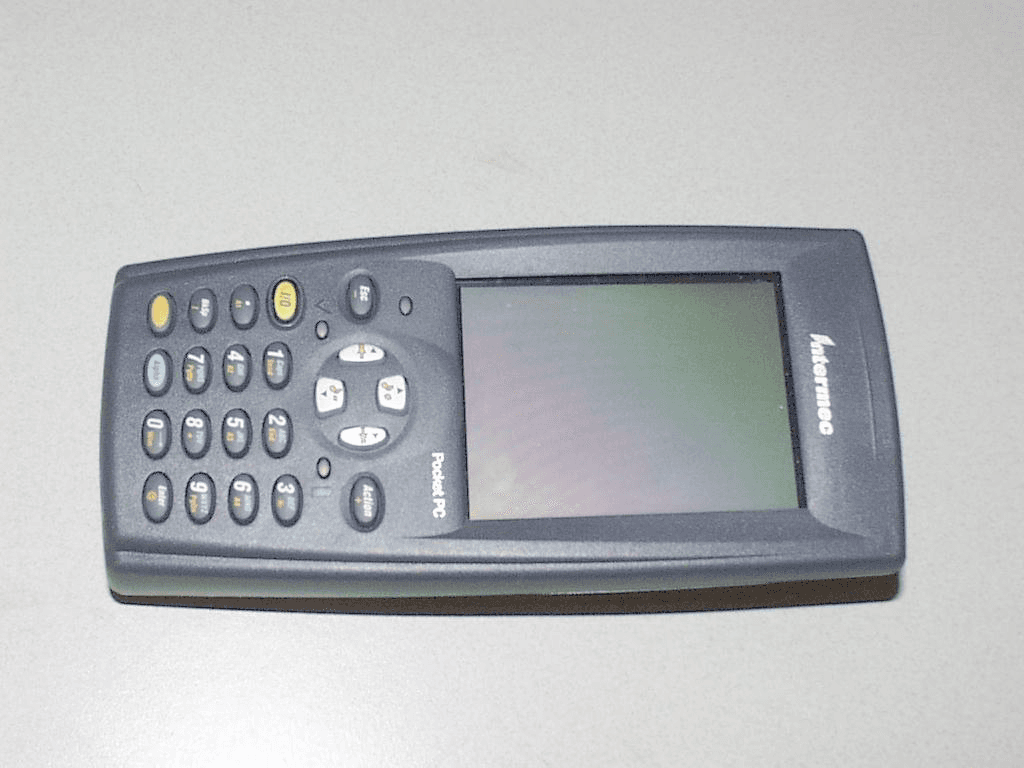
Click to zoom
Application Details
- Equipment Class
- DTS - Digital Transmission System
- Date of Grant
- Oct 13, 2002
- Application Purpose
- Original Equipment
- Date of Application
- Oct 13, 2002
- Equipment Note
- 700C
- Frequency Range
- 2412.00000000 - 2462.00000000
- Country
- United States
Documents & Files
Document Text
Text extracted from the exhibit documents filed with the FCC. Open a document above to read the original.
Users Manual
Exhibit J: User Manual FCC ID: HN22011B Part No. 072719-001 Important 700C-802.11b Information! Contents For Users in the United States and Canada ........................................................................2 For Users Outside of the United States and Canada ..............................................................3 Pour les utilisateurs en dehors du Canada et des Etat-unis .....................................................4 Für Benutzer außerhalb von Kanada und den Vereinigten Staaten .............................................5 Per gli utenti al di fuori del Canada o degli Stati Uniti ...........................................................6 Para Usuarios Fuera de Canada o de los Estados Unidos........................................................7 Para Usuários Fora do Canadá ou dos Estados Unidos ...........................................................8 2 For Users in the United States and Canada Place this supplement in your manual. This device complies with Part 15 of the FCC Rules and with RSS-210 of Industry Canada. Operation is subject to the following two conditions: (1) This device may not cause harmful interference, and (2) This device must accept any interference received, including interference that can cause undesired operation. Federal Communications Commission Compliance FCC Digital Emissions Compliance This equipment has been tested and found to comply with the limits for a Class B digital device, pursuant to Part 15 of the FCC Rules. These limits are designed to provide reasonable protection against harmful interference in a residential installation. This equipment generates, uses, and can radiate radio frequency energy and, if not installed and used in accordance with the instructions, may cause harmful interference to radio communications. However, there is no guarantee that interference will not occur in a particular installation. If this equipment does cause harmful interference to radio or television reception, which can be determined by turning the equipment off and on, the user is encouraged to try to correct the interference by one or more of the following measures: •Reorient or relocate the radio or television receiving antenna. •Increase the separation between the computer equipment and receiver. •Connect the equipment to an outlet on a circuit different from that to which the radio or television receiver is connected. •Consult the dealer or an experienced radio television technician for help. Operation Warning To comply with the FCC’s RF exposure requirements and minimize health hazards: The user shall not touch the antenna of this device when the device is in use. The user shall ensure that the device is at least 20 cm (8 in) away from their body when the transceiver is in use. Caution Changes or modifications not expressly approved by Intermec could void the user’s authority to operate this equipment. Industry Canada Compliance This Class B digital apparatus meets all requirements of the Canadian Interference-Causing Equipment Regulations. This device requires a radio license unless it is used totally inside a building. (The user must obtain this license.) Cet appareil numérique de la classe B respecte toutes les exigences du Règlement sur le matériel brouilleur du Canada. Cet appareil exige une license radio à moins d’être entièrement installé dans un bâtiment. (L’utilisateur doit obtenir cette license.) 3 Agency Approvals This device is UL Listed. For Users Outside of the United States and Canada The Intermec product you purchased transmits and receives data using a 2.4 GHz Direct Sequence Spread Spectrum system. Programming and configuration information for the transceivers is also provided in the host device documentation. Please check the Intermec Web site for additional documentation at www.intermec.com. Hereby, Intermec Technologies Corporation declares that this Model 700C-802.11b is in compliance with the essential requirements and other relevant provisions of R&TTE Directive (1999/5/EC). This product has been assessed to the following standards: •ETSI EN 300 328-2 v1.2.1 (2001-12) •ETSI EN 301 489-17 v1.1.1 (2001-09) •EN 60950:1992 (incl. Amdt. 1-4, 11) •SP/DGPT/ATAS 23 (1995-02) The original Declaration of Conformity is available on the Intermec Technologies Corporation Web site at www.intermec.com. This product transmits electromagnetic waves at 2.4 GHz frequency range. It has been tested and found compliant with U.S. (OET Guide 65) and Canadian (RSS 102) RF exposure regulations. There are no regulations covering this product type in the EU at this time. The transmitter module’s output power is 89 mW. The products using this module are intended for business and industrial environments. They should not be used in residential environments and by children. This product is marked with this logo and uses radio frequency bands that are not harmonized throughout the European Community. The following table indicates the areas of intended use of the equipment and any known restrictions. 4 Country of Intended UseLicense YesNoRequiredRestrictions Details AustriaX BelgiumXXIf this product is used outdoors, then it is restricted to 2460 MHz to 2483.5 MHz. DenmarkX FinlandX FranceXXFrequency operation restricted to 2462 MHz to 2472 MHz. GermanyX GreeceX IrelandX ItalyX LuxembourgX The NetherlandsX PortugalX SpainX SwedenX United KingdomX Other non-EU: IcelandX LiechtensteinX NorwayX SloveniaX SwitzerlandX Additional EMI/RFI Compliance This device meets the Class B limit requirements of CISPR 22. Pour les utilisateurs en dehors du Canada et des Etat-unis Le produit Intermec que vous avez acheté peut transmettre et recevoir des données à l’aide d’un système d’étalement du spectre en séquence directe de 2,4 GHz. Les informations de programmation et de configuration pour les émetteurs-récepteurs sont également fournies dans la documentation de l’appareil hôte. Pour obtenir toute documentation supplémentaire, veuillez consulter le si…
Text truncated - open the document above for the full version.
Cover Letter(s)
Exhibit K: Request for Confidentiality FCC ID: HN22011B
Cover Letter(s)
Northwest EMC TCB Approval Opinion Revision 05//02 INMC0019 Information about the Applicant Applicant: Intermec Corporation Address: 6001 36 th Avenue West City, State, Zip Everett, WA 98203-9280 Test Requested By: Carl Turk Model: 700C FCC ID: HN22011B Agent Applicant Approval Type Reference Northwest EMC Technical Report – General Information Equipment Type Reference Northwest EMC Technical Report – General Information Rule Part Reference Northwest EMC Technical Report – General Information Overview This radio is compliant with IEEE 802.11b specifications, and will be used only in the applicant’s 700C terminal as a mobile transmitter. Symbol Technologies was previously granted certification for this same radio module (FCC ID: H9PLA4137P). The applicant is not seeking to modify or alter Symbol Technologies grant in any way. A separate technical report prepared by Intertek Testing Services for the Symbol Technologies application documents compliance of the radio. The applicant certifies that the radios described in both technical reports are identical. The applicant has provided attestations supporting that certification. The only changes the applicant is proposing are for two different antennas and to operate it in the 700C terminal. Since no other changes have been made, only those tests that are directly affected were repeated, the approval is based upon the previous testing for all other tests. That information has been reviewed, but taken at face value as an approved product. The 700C also uses a Bluetooth radio, FCC ID: HN2ABTM3-2. It is a mobile transmitter that will be approved for use in the 700C. The RF Exposure exhibit demonstrates compliance of both co-located radios. General Comments Item The TCB 410, Application for Certification, is incorrect; it states the wrong model number. A corrected application must be submitted. Resolution The applicant has submitted a corrected form. Item Provide statement that provides evidence that the antenna meets the requirements of 47 CFR, 15.203. Resolution The applicant to satisfy the requirement has provided information. Northwest EMC TCB Approval Opinion Revision 05//02 INMC0019 Opinion Specification Requirements Description 15.207 Conducted Emissions Opinion: The Equipment meets the intent specified by the requirements listed above. Discussion: The Applicant has submitted test results in the form of a test report. Reference: Exhibit L, M, and N Specification Requirements Description 15.247(a) Bandwidth Opinion: The Equipment meets the intent specified by the requirements listed above. Discussion: The Applicant has submitted test results in the form of a test report Reference: Exhibit L, M, and N Specification Requirements Description 15.247(b) Power Output Opinion: The Equipment meets the intent specified by the requirements listed above. Discussion: The Applicant has submitted test results in the form of a test report Reference: Exhibit L, M, and N Specification Requirements Description 15.247( c ) Spurious Emissions, Antenna Conducted Opinion: The Equipment meets the intent specified by the requirements listed above. Discussion: The Applicant has submitted test results in the form of a test report Reference: Exhibit L, M, and N Specification Requirements Description 15.247( c ) Spurious Emissions, Radiated Emissions Opinion: The Equipment meets the intent specified by the requirements listed above. Discussion: The Applicant has submitted test results in the form of a test report. Reference: Exhibit O Northwest EMC TCB Approval Opinion Revision 05//02 INMC0019 Specification Requirements Description 15.247(d) Power Spectral Density Opinion: The Equipment meets the intent specified by the requirements listed above. Discussion: The Applicant has submitted test results in the form of a test report Reference: Exhibit L, M, and N Specification Requirements Description 15.247(b)(4) RF Exposure Opinion: The Equipment meets the intent specified by the requirements listed above. Discussion: The Applicant has submitted MPE estimates demonstrating compliance. Reference: Exhibit H
External Photos
Exhibit C: External Photos from Intel FCC ID: HN22011B
External Photos
Exhibit C: External Photos from Intel FCC ID: HN22011B
External Photos
Exhibit C: External Photos from Intel FCC ID: HN22011B
ID Label/Location Info
Exhibit A: FCC ID Label FCC ID: HN22011B
Internal Photos
Exhibit D: Internal Photos FCC ID: HN22011B Bottom of Radio, Shield Removed Top of Radio, Shield Removed Bottom Of Radio Top of Radio
Internal Photos
Exhibit D: Internal Photos FCC ID: HN22011B
Operational Description
Exhibit G: Antenna Information FCC ID: HN22011B 700C Antennas: Antenna Type Gain Manufacturer Part Number External Tuned Dipole 1.3 dBi Mobilemark 805-606 Internal Folded monopole -2 dBi (avg.) SeaRay 805-608 Intermec Technologies Corporation 6001 36 th Avenue West Everett, WA 98203-9280 425.356.1765 tel 425.348.2633 fax www.intermec.com October 1, 2002 To Whom It May Concern: Intermec complies with the unique connector requirement of FCC Part 15.203 by using a custom made reverse gender SMA connector. This custom made antenna connector is not available off-the-shelf to consumers. If you have any questions regarding this product, please feel free to contact me (phone: 425 348 2600 ext 6214, fax: 425 348 2633, email: [email protected]). Sincerely, Cheryl D. White Compliance Engineer Intermec Technologies Corp.
Operational Description
Exhibit I: Operational Description FCC ID: HN22011B TABLE OF CONTENTS 1. Introduction 1.1 Trilogy Product Background Trilogy products transfer data at Ethernet speeds (11Mbps instantaneous data rate) over the air between two or more users or between a user and the wired network. The WLAN is not a single product, it is a digital radio system with product components that can be configured to meet a multitude of customer requirements. The Trilogy Access Point links to a wired LAN via a wired Ethernet connection. Wireless NICs communicate to the wired LAN through the AP. Multiple Access Points are deployed in a cellular layout plan similar in concept to the cellular telephone base station layout. 1.2 Purpose This document defines the functional characteristics of the Trilogy 3 CF Adapter Mobile Unit (MU). Much of the basic functionality is provided by Intersil as part of their 802.11 DS implementation for the Intersil PRISM radio using the Intersil HFA3842/3873 microcontroller. In particular, the host interface access mechanisms, packet send, receive, queuing, timer services, and buffer management are already implemented and do not require further development. Therefore, this document primarily addresses the Symbol radio configuration and firmware enhancements required for the Trilogy product. Detailed descriptions of the operation of the CF host interface (PCMCIA) may be found in the Programmer’s Manual from Intersil and CF+ and CompactFlash Specification Revision 1.4 . 1.3 Goals The adapter will support all required modes of operation as an 802.11 Direct Sequence MU or as an AP transmit/receive sub-system The adapter will support station operation in CAM and PSP modes, as well as certain features required for site survey 1. Introduction 1.2 TrilogyProduct Background 1.3 Purpose 1.4 Goals 1.5 Key Features 1.6 What Will Not be Supported 1.7 References 2. Architecture 2.1 System Architecture 2.2 Component Descriptions 2.3 Hardware Environment 3. Block Diagrams 3.1 Transmitter Path 3.2Receive Path 3.3 Microprocessor Control 3.4Frequency Generation 4. RF Signal Performance 4.1 Specifications 4.2 State Timing 4.3 Carrier Sense/ Clear Channel Assessment 5. Product Power Requirements 5.1 Operating Current 6. REGULATORY Page 1 of 9Product Name 6/12/2002http://quality.intel.com/CPR/telecom/wlo/Trilogy%20III%20Compact%20Flash/WCF2011/T3%20CF%20description.htm... The adapter will support adaptive frequency changes for compatible DS Access Points, in countries that support more than one channel In production, the adapter will utilize the HFA3873 combination MAC and Baseband in place of the individual HFA3842 and 3863 devices outlined in this specification. The primary purpose for the conversion is to reduce product cost and achieve a single sided PCB design. 1.4 Key Features • Direct Sequence 802.11 physical layer • High data rate capability – 11 MBPS, 5.5 MBPS, 2 and 1 MBPS • 3.3 volt CF Type I thickness with and Type II thickness on the extended section for the internal antenna package. • 16 bit host interface using PCMCIA/CF IO mode • In-line WEP algorithm • Enhanced power save algorithm • Robust roaming and dynamic rate switching • Pin 45(SPKR) can be wired to provide an active high Media Free (MF) signal level for S24/BloothTooth coexistence support 1.5 What Will Not be Supported The adapter will not support an ultra-low power mode of operation (< 1 ma). For PSP mode, it will remove power to as many circuits as possible, but clock control limitations prevent the HFA3842 controller from using a 32 KHz or other low power oscillator for sleep mode. The adapter will not support sleep mode, nor will the driver require wake- up/resume operations since the controller and clock will always be active (although the adapter will consume as little power as possible when there are no receive, transmit, internal (roam) or host activities in progress) 1.6 References 1.6.1 Internal References • Trilogy MU Firmware-Driver Interface Specification, Bob Neilsen • Trilogy Network Interface PC Card Product Requirements Document • Trilogy Network Interface PCI Card Product Requirements Document • Trilogy Access Point Product Requirements Document • qual_environmental_PCI_plan, Qualification plan for the PCI Card • qual_environmental_PCC_plan Qualification plan for the PC Card • qual_environmental_ AP_plan Qualification plan for the Access Point Page 2 of 9Product Name 6/12/2002http://quality.intel.com/CPR/telecom/wlo/Trilogy%20III%20Compact%20Flash/WCF2011/T3%20CF%20description.htm... • SS-03800-74, Environmental Guideline and Qualification Test Standard 1.6.2 HFA3842 References Note – The following documents are proprietary and confidential • HFA3842 Programmer’s Manual • HFA3842 Hardware Reference Manual 1.6.3 Other Device Specifications • HFA3863A Direct Sequence Spread Spectrum Baseband Processor, Intersil Semiconductor, 1999 • HFA 3783/3685A Direct Sequence RF Modem, Intersil • EM128C16 - 128K by 16 bit Ultra Low power Asynchronous Static RAM bit, Enable Semiconductor, www.enablesemi.com, 10/98 • M24C08-W, ST Microelectronics , 8K by 1 bit 3-volt only, Serial I2C EEPROM. 1.6.4 External References • Wireless LAN Medium Access Control (MAC) and Physical Layer (PHY) Specifications, IEEE 802.11, D8.0 1 May 1998 (Or current approved specification) • Draft 802.11 Specification for High Speed Wireless LANs (TBS) • PC Card Standard (Version 2.01), Personal Computer Memory Card Internal Association, 1995 (or latest revision) • CF+ and CompactFlash Specification Revision 1.4 . 2. Architecture 2.1 System Architecture The adapter consists of a 2.4 GHz radio with direct sequence transmit and receive circuitry using Intersil 3863 Base Band Processor and HFA3685/HFA3783 Intersil chipset known as the PRISM 2.5 chipset. The controller circuitry consists of an Intersil HFA3842/3873 MAC controller with PCMCIA interface, EEPROM and SRAM. Crystal oscillators are used to drive the controller and transmit/receive circuits. Power control …
Text truncated - open the document above for the full version.
RF Exposure Info
Exhibit H: RF Exposure FCC ID: HN22011B Compliance with 47 CFR 15.247(b)(5) “Systems operating under the provisions of this section shall be operated in a manner that ensures that the public is not exposed to radio frequency energy levels in excess of the Commission's guidelines. See § 1.1307(b)(1) of this chapter.” The EUT will only be used with a separation distance of 20 centimeters or greater between the antenna and the body of the user or nearby persons and can therefore be considered a mobile transmitter per 47 CFR 2.1091 (b). No radiating structure will be within 2.5cm of the user’s hands or wrists. The EUT will only be used in the applicant’s Model 700C Hand-held Terminal. There are no provisions for body worn configurations. The 700C can be configured with the EUT and a Bluetooth radio (FCC ID: HN2ABTM3- 2). The maximum peak power was measured to be 73.2 mW (ERP) for FCC ID: HN2011B, and 0.61 mW (ERP) for FCC ID: HN2ABTM3-2. The transmit frequency is greater than 1.5 GHz, therefore the EUT is categorically excluded from routine environmental evaluation per 47 CFR 2.1091(c). The MPE estimates are as follows: Table 1 in 47 CFR 1.1310 defines the maximum permissible exposure (MPE) for the general population as 1mW/cm 2 . The exposure level at a 20 cm distance from the EUT’s transmitting antenna is calculated using the general equation: S = (PG)/4πR 2 Where: S = power density (mW/cm 2 ) P = power input to the antenna (mW) G = numeric power gain relative to an isotropic radiator R = distance to the center of the radiation of the antenna (20 cm = limit for MPE estimates) PG = EIRP Solving for S, the maximum power densities 20 cm from the transmitting antennas are summarized in the following tables: MPE Estimates for Self Co-located Device FCC ID: HN2011B 802.11 (b) Radio Antenna Type Antenna Part No. Transmit Frequency Max Peak Conducted Output Power Antenna Gain Minimum Antenna Cable Loss Power Density @ 20 cm General Population Exposure Limit from 1.1310 Ratio of Power Density to the Exposure Limit (MHz) (mW) (dBi) (dB) (mW/cm 2 ) (mW/cm 2 ) External tuned dipole 805-606 2400 89 1.3 0 0.024 1 0.024 Internal folded monopole 805-608 2400 89 -2 0 0.011 1 0.011 Worst Case Ratio of Power Density to the Exposure Limit = 0.024 ( External Tuned Dipole Antenna) FCC ID: HN2ABTM3-2 Bluetooth Radio Antenna Type Antenna Part No. Transmit Frequency Max Peak Conducted Output Power Antenna Gain Minimum Antenna Cable Loss Power Density @ 20 cm General Population Exposure Limit from 1.1310 Ratio of Power Density to the Exposure Limit (MHz) (mW) (dBi) (dB) (mW/cm 2 )(mW/cm 2 ) Internal Integral Antenna ABTM3 2400 3.78 -5.77 0 0.000201 0.00020 Worst Case Ratio of Power Density to the Exposure Limit = 0.00020 (Internal Integral Antenna) Exposure Scenarios for 700C Per Note 24 shown below (taken from FCC slides), the Sum of Worst Case Power Ratios cannot exceed 1.0 802.11b Radio Worst Case Ratio of Power Density to the Exposure Limit (FCC ID: HN2011B) Bluetooth Radio Worst Case Ratio of Power Density to the Exposure Limit (FCC ID: HN2ABTM3-2) Sum of Worst Case Ratios (Power Density to the Exposure Limit) FCC Limit for Sum of Worst Case Ratios 0.02400 0.00020 0.02420 1.0 PASS no radio 0.00020 0.00020 1.0 PASS 0.02400 no radio 0.02400 1.0 PASS The results shown in the above table are equivalent to the Sum of the EIRP of the Two Co-located Transmitters (EIRP TX1 + EIRP TX2) compared to the exposure limit. The benefit of this method, is that it accounts for transmitters operating at different frequencies against different exposure limits. Please note that EIRP = ERP x 1.64, so EIRP is worst case. However, because some parties would prefer to see the calculation as the Sum of the ERP of the Two Co-located Transmitters, the table below shows compliance with ERP TX1 + ERP TX2 802.11b Radio (FCC ID: HN2011B) Worst Case ERP Bluetooth Radio (FCC ID: HN2ABTM3-2) Worst Case ERP Sum of Worst Case ERPs Power Density @ 20 cm General Population Exposure Limit from 1.1310 (mW) (mW) (mW) (mW/cm 2 )(mW/cm 2 ) 73.21 0.61 73.82 0.01469 1.0 PASS no radio 0.61 0.61 0.00012 1.0 PASS 73.21 no radio 73.21 0.01456 1.0 PASS Excerpts from TCB Training, April 3, 2002, “Mobile Transmitters”, Slide 6: “Devices operating in multiple frequency bands When RF exposure evaluation is required for TCB approval o Separate antennas – estimated minimum separation distances may be considered for the frequency bands that do not require evaluation or TCB approval, however, the estimated distance should take into account the effect of co-located transmitters. (Note 24) Note 24 According to multiple frequency exposure criteria, the ratio of field strength or power density to the applicable exposure limit at the exposure location should be determined for each transmitter and the sum of these ratios must not exceed 1.0 for the location to be compliant .” The sum of the worst-case power ratios in any scenario does not exceed 1.0 (see Note 24 above); therefore, the exposure condition is compliant with FCC rules.
Test Report
Exhibit B: Technical Report-General Information FCC ID: HN22011B Measurement/Technical Report General Information Applicant: Intermec Corporation Address: 6001 36 th Avenue West City, State, Zip Everett, WA 98203-9280 Test Requested By: Carl Turk Model: 700C FCC ID: HN22011B First Date of Test: June 10, 2002 Last Date of Test: September 22, 2002 Receipt Date of Samples: June 10, 2002 Job Number INMC0019 Scope Regulatory Authority Federal Communications Commission Approval Type Certification Equipment Type Unlicensed, Low Power Spread Spectrum Transmitter Rule Part 47 CFR 15.247(c) Rule Exemptions None Related Submittals or Grants None Report Information Prepared By Vicki Albertson, Technical Report and Documentation Manager Northwest EMC, Inc. Signature Issued By Northwest EMC, Inc. 22975 NW Evergreen Parkway, Suite 400 Hillsboro, Oregon 97124 Ph. (503) 844-4066 Fax (503) 844-3826 Report Number INMC0019 Date Issued September 26, 2002 Test Facility The measurement facility used to collect the radiated and conducted data is located at Northwest EMC, Inc. 22975 NW Evergreen Parkway, Suite 400 Hillsboro, OR 97124 (503) 844-4066 Fax: 844-3826 This site has been fully described in a report filed with the FCC (Federal Communications Commission), and accepted by the FCC in a letter maintained in our files. Laboratory Accreditation A2LA has granted accreditation to Northwest EMC, Inc. to perform the Electromagnetic Compatibility (EMC) tests described in the Scope of Accreditation. Assessment performed to ISO/IEC 17025. Certificate Number: 1936-01, Certificate Number: 1936-02, Certificate Number 1936-03 FCC ID: HN22011B Exhibit A FCC ID Label Exhibit B Technical Report-General Information Exhibit C External Photos Exhibit D Internal Photos Exhibit E Schematics Exhibit F Block Diagram Exhibit G Antenna Information Exhibit H RF Exposure Exhibit I Operational Description Exhibit J User Manual Exhibit K Request for Confidentiality Exhibit L Symbol Test Report 1 Exhibit M Symbol Test Report 2 Exhibit N Symbol Test Report 3 Exhibit O Spurious Radiated Emissions Exhibit P Test Setup Photos Exhibit Q Attestation Letter for Equiv. to H9PLA4137P
Test Report
Exhibit L: Symbol Test Report 1 FCC ID: HN22011B 1365 Adams Court Menlo Park, CA 94025 Symbol Technologies, Model No. LA-4137Date of Test: April 1 to May 24, 2001 FCC ID: H9PLA4137P File: 2046983D1Version 1.0Page 2 of 55 15.247 Direct Sequence Table of Contents 1.0Summary of Tests.................................................................................................................................3 2.0General Description.............................................................................................................................4 2.1Product Description..................................................................................................................4 2.2Related Submittal(s) Grants.....................................................................................................4 2.4Test Facility...............................................................................................................................5 3.0System Test Configuration..................................................................................................................6 3.1Support Equipment and description.........................................................................................6 3.2Block Diagram of Test Setup...................................................................................................6 3.3Justification...............................................................................................................................7 3.4Software Exercise Program.......................................................................................................7 3.5Mode of Operation During Test...............................................................................................7 3.6Modifications Required for Compliance..................................................................................7 4.0Measurement Results...........................................................................................................................8 4.1Conducted Output Power at Antenna Terminals......................................................................8 4.26 dB RF Bandwidth..................................................................................................................9 4.3Power Density.........................................................................................................................13 4.4Out-of-Band Conducted Emissions........................................................................................22 4.5Out-of-Band Radiated Emissions...........................................................................................45 4.6Transmitter Radiated Emissions in Restricted Bands............................................................46 4.7AC Line Conducted Emission.................................................................................................50 4.8Radiated Emissions from Digital Section of Transceiver (Transmitter)................................52 4.9Radiated Emissions from Receiver Section of Transceiver (L.O. Radiation)........................53 5.0 List of test Equipment........................................................................................................................54 6.0Document History...............................................................................................................................55 1365 Adams Court Menlo Park, CA 94025 Symbol Technologies, Model No. LA-4137Date of Test: April 1 to May 24, 2001 FCC ID: H9PLA4137P File: 2046983D1Version 1.0Page 4 of 55 15.247 Direct Sequence 2.0General Description 2.1Product Description The Symbol Technologies model LA-4137 is a 2.4 GHz Direct Sequence Spread Spectrum radio in the form of a PC Card that is used for wireless communication form a LAN to remote wireless devices. This device is used in a portable configuration and can be located close to personnel. Antennas are mounted in pairs for diversity. Overview of WLAN Compact Flash Card Model: LA-4137 ApplicantSymbol Technologies Trade Name & Model No.Symbol Technologies, LA-4137 FCC IdentifierH9PLA4137P Use of ProductWireless LAN communications Manufacturer & Model of Spread Spectrum Module Symbol Technologies Type of TransmissionDirect Sequence Spread Spectrum Rated RF Output89 mW, 19.5 dBm Frequency Range2412 - 2462 Number of Channel(s)11 Antenna(s) & Gain, PCB Chip, Model Trilogy CF, 2 dBi Antenna Requirement [X] The EUT uses a permanently connected antenna. [ ] The antenna is affixed to the EUT using a unique connector which allows for replacement of a broken antenna, but DOES NOT use a standard antenna jack or electrical connector. [ ]The EUT requires professional installation (attach supporting documentation if using this option). Manufacturer name & addressSymbol Technologies 6480 Via Del Oro San Jose, CA 95119-1208 2.2Related Submittal(s) Grants None. 1365 Adams Court Menlo Park, CA 94025 Symbol Technologies, Model No. LA-4137Date of Test: April 1 to May 24, 2001 FCC ID: H9PLA4137P File: 2046983D1Version 1.0Page 5 of 55 15.247 Direct Sequence 2.3Test Methodology Radiated emissions measurements were performed according to the procedures in ANSI C63.4 (1992). Radiated tests were performed at an antenna to LA-4137 distance of 3 meters, unless stated otherwise in the "Data Sheet" of this Application. All other measurements were made in acco…
Text truncated - open the document above for the full version.
Contact Information
Applicant
Brian Rudick(VP & GC, Honeywell Scanning & Mobility)
Technical Contact
Northwest EMC, Inc.Greg V Kiemel
[email protected]503-844-4066
22975 NW Evergreen Parkway · Hillboro, Oregon · United States
Non-Technical Contact
Northwest EMC, Inc.Vicki Albertson
[email protected]503-844-4066
Test Firm
Northwest EMC, Inc.Greg Kiemel
Technical Specifications
| # | Rule Parts | Frequency Range | Power Output |
|---|---|---|---|
| 1 | 15C | 2.41 GHz - 2.46 GHz | 89.00 mW |
Other Applications from Intermec Technologies Corporation

HN2-BTM311
Nov 23, 2004BTM311
Equipment Class
DTS - Digital Transmission System
HN2-802CF13E
Nov 07, 2004EasyLAN
Equipment Class
DTS - Digital Transmission System
HN2WAMIG2
Nov 18, 2003802MIG2
Equipment Class
DTS - Digital Transmission System
HN2SB555-2
Sep 04, 2003SB555 Radio in 700C
Equipment Class
PCE - PCS Licensed Transmitter held to ear
HN22011B-2
Jul 28, 20032011B Radio in 700C
Equipment Class
DTS - Digital Transmission System