HN22106Access Point, 2106
Intermec Technologies Corporation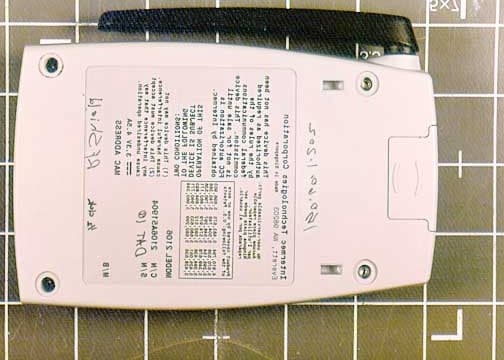
Click to zoom
Application Details
- Equipment Class
- NII - Unlicensed National Information Infrastructure TX
- Date of Grant
- Feb 05, 2002
- Application Purpose
- Original Equipment
- Date of Application
- Feb 05, 2002
- Equipment Note
- Access Point, 2106
- Frequency Range
- 5250.00000000 - 5327.50000000
- Country
- United States
Documents & Files
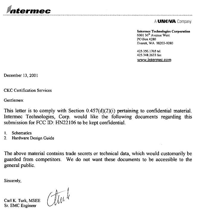
Document Text
Text extracted from the exhibit documents filed with the FCC. Open a document above to read the original.
Users Manual
Caution You must use the appropriate Intermec power supply with this device or equipment damage may occur. Conseil Vous devez utiliser la source d’alimentation Intermec adéquate avec cet appareil sinon vous risquez d’endommager l’équipement. Caution Government regulatory agencies mandate that the antenna not be alterable. Therefore, the access point uses a custom antenna connector. Do not attempt to use a different antenna or you may damage the connector and the access point. Conseil Les agences responsables de la réglementation gouvernementale exigent que l’antenne ne soit pas modifiable. Par conséquent, le point d’accès est doté d’un connecteur d’antenne personnalisé. Ne pas essayer d’utiliser une antenne différente au risque d’endommager le connecteur et le point d’accès. Quick Start Guide MobileLAN ™ access 2106 More Information About the 2106 Safety First Specifications Physical 14.66 cm x 9.32 cm x 3.53 cm Operating 0∞C to +40∞C Dimensions (5.77 in x 3.67 in x 1.39 in) Temperature (+32∞F to +104∞F) Weight 205 g (0.45 lb) Electrical rating ~100 to 240V 1.0 to 0.5A 50 to 60 Hz For more information on using the 2106, please see: • 21XX Universal Access Point Technical Reference Manual (Part No. 067150) • Intermec Web Site at www.intermec.com Part No. 072215-001 *072215-001* *072215-001* 072215-001 6001 36th Avenue West Everett, WA 98203-9280 © 2001 Intermec Technologies Corp. All Rights Reserved Intermec’s 2106 access point is a wireless local area network (LAN) product that lets your wireless end devices roam anywhere throughout an enterprise while maintaining a continuous, high-quality network connection. Your 2106 has been certified with an IEEE 802.11a radio. CAUTION ! CAUTION ! MobileLAN ™ access 2106 Quick Start Guide Power After the 2106 boots, this LED remains steadily on. Wired LAN This LED flashes when a frame is transmitted or received on the Ethernet port. Root/error This LED flashes if this access point is configured as the root. It remains steadily on if an error has occurred. Radio This LED flashes when a frame is transmitted or received on the Radio port. 1. Install the MobileLAN access Utility by clicking Install Software from the enclosed CD and following the instructions that appear on your screen. You can also install the software from www.mobilelan.intermec.com. 2. Reboot the access point and configure parameters A through C in the MobileLAN access Utility main screen. Note: You must configure parameters A through C within 60 seconds after the access point has started. In addition, if the access point you are setting is connected wirelessly, you must have an active radio connection. Your PC must also be on the same Ethernet segment and subnet as the access point. 11 3 Use this position when storing the 2106. Use this position when the 2106 is mounted on a desktop. Use this position when the 2106 is mounted to a wall. 0∞ 90∞ 180∞ Defining the LEDs, Ports, and Antenna Positions Connecting, Mounting, and Applying Power to the 2106 Setting an Initial IP Address Plug the AC power cord into an AC power outlet. Plug the power supply into the power port of the 2106. Power Supply Ethernet connection A Enter the IP address of the access point. B Enter the MAC address of the access point (located on the bottom of the access point). C Click Set AP. Click Configure AP to use the Web browser interface to continue configuring the access point. Power port 10/100 BaseT Ethernet port Congratulations! Your 2106 is now ready to begin transmitting data packets between your end devices and your wired network. Mounting screw (not provided) (2 places) Screws fasten into mounting surface. Fit the slots on the back of the 2106 over the hooks on the mounting bracket.
Block Diagram
Model 2106 Block Diagram MOT 8245 Processor SDRAM 8 Meg Bytes Flash 4 Meg Bytes Advanced 802.11a Radio, 5.25 GHz 100/10 Base T ETHERNET MAC and PHY INTEGRATED ACCESS POINT, HIGH RATE RADIO BLOCK DIAGRAM Memory Bus PCI Bus EJTAG PCI pad out J1 J2 J3 2.5 V and 2.0 V Regulator Parallel Expansion port Reset Circuitry 33 MHz Clock J4 LED Status Indicators Card ID I2C bus . Serial 25 MHz Clock Power Ethernet
RF Exposure Info
Part No. 072382-001 Important 2106 Information! Place this supplement in your manual. For Users in the United States and Canada This device complies with Part 15 of the FCC Rules and with RSS-210 of Industry Canada. Operation is subject to the following two conditions: (1) This device may not cause harmful interference, and (2) This device must accept any interference received, including interference that can cause undesired operation. Federal Communications Commission Compliance This equipment is intended for operation in a commercial environment, in compliance with the requirements for a Class A digital device, pursuant to Part 15 of the FCC Rules, and it must not be used in a residential environment. It generates, uses, and can radiate radio frequency energy. If not installed and used in accordance with the instruction manual, it may cause interference to radio communications. If this equipment causes interference, the user will be required to correct the interference at the user’s own expense. The operation of this device is restricted to indoors on. Note: To maintain compliance with FCC Rules, the input/output (I/O) cables that interconnect between the device and any peripheral must be as specified by Intermec. Operation Warning To comply with the FCC’s RF exposure requirements and minimize health hazards: The user shall stay at least 20 cm (8 in) away from the antenna of this device, when the device is in use. Installation Warning To comply with the FCC’s RF exposure requirements and minimize health hazards: Access points must be installed in such a way that the user will be at least 20 cm (8 in) away from the antenna, when the device is in use. The installers should not forget that the burden of maintaining this distance is on the installer and not the user. The antennas should be installed in a manner that will comply with this requirement. Caution Changes or modifications not expressly approved by Intermec could void the user’s authority to operate this equipment. Industry Canada Compliance This Class A digital apparatus meets all requirements of the Canadian Interference- Causing Equipment Regulations. This device requires a radio license, unless it is used totally inside a building. (The user must obtain this license.) Cet appareil numérique de la classe A respecte toutes les exigences du Règlement sur le matériel brouilleur du Canada. Cet appareil exige une license radio à moins d’être entièrement installé dans un bâtiment. (L’utilisateur doit obtenir cette license.) Agency Approvals This device is UL and cUL listed (UL 1950/C22.2 #950) for safety when powered by an Intermec power supply. Part No. 072382-001 *072382-001* *072382-001* 6001 36th Avenue West Everett, WA 98203-9280 © 2001 Intermec Technologies Corp. All Rights Reserved
Test Report
Page 1 of 64 Report No.: FC02-008A ADDENDUM TO FC02-008 FOR THE ACCESS POINT, 2106 FCC PART 15 SUBPART C SECTIONS 15.407, 15.207 & 15.209 AND FCC PART 15 SUBPART B SECTIONS 15.107 & 15.109 CLASS B COMPLIANCE DATE OF ISSUE: JANUARY 31, 2002 PREPARED FOR: Intermec Technologies 6001 36th Avenue West WA, 98203-9280 PREPARED BY: Joyce Walker CKC Laboratories, Inc. 5473A Clouds Rest Mariposa, CA 95338 P.O. No.: 4500051648 W.O. No.: 78067 Date of test: December 12, 2001 – January 18, 2002 Report No.: FC02-008A This report contains a total of 64 pages and may be reproduced in full only. Partial reproduction may only be done with the written consent of CKC Laboratories, Inc. Page 2 of 64 Report No.: FC02-008A TABLE OF CONTENTS Administrative Information .........................................................................................................4 Summary of Results.....................................................................................................................5 Modifications Required for Compliance .....................................................................................5 Approvals.....................................................................................................................................5 Equipment Under Test (EUT) Description ..................................................................................6 EUT Operating Frequency..............................................................................................6 15.203 Antenna Requirements........................................................................................6 15.33 Frequency Range Tested.......................................................................................6 15.205 Restricted Bands .................................................................................................6 Equipment Under Test .................................................................................................................7 Peripheral Devices .......................................................................................................................7 Report of Measurements ..............................................................................................................8 Table 1: 15.407(a)(1)&(2) Peak Output Power (ERP) ...................................................8 Table 2: 15.209/15.407(b)(5) Six Highest Radiated Emission Levels: 20-1000 MHz ...9 Table 3: 15.407(b)(1)&(2) Six Highest ERIP Emission Levels: 1-40GHz ....................10 Table 4: 15.209/15.407(b)(1)&(2) Six Highest Radiated Emission Levels: 1-40GHz ...11 Table 5: 15.207 Six Highest Conducted Emission Levels..............................................12 Table 6: 15.107 Six Highest Conducted Emission Levels: Receiver Verification .........13 Table 7: 15.109 Six Highest Radiated Emission Levels: Receiver Verification ............14 15.407(a)(1) Occupied Bandwidth Summary .................................................................15 15.209/15.247(b) Bandedge - 5.15GHz ..........................................................................18 15.209/15.247(b) Bandedge - 250% ...............................................................................19 15.209/15.247(b) Bandedge - 5.35GHz ..........................................................................20 15.407(a)(5) Peak Power Spectral Density - 5.18GHz ...................................................21 15.407(a)(5) Peak Power Spectral Density - 5.24GHz ...................................................22 15.407(a)(5) Peak Power Spectral Density - 5.34GHz ...................................................23 15.407(a)(6) Peak Excursion Ratio - 5.18GHz ...............................................................24 15.407(a)(6) Peak Excursion Ratio - 5.24GHz ...............................................................25 15.407(a)(6) Peak Excursion Ratio - 5.32GHz ...............................................................26 15.407(g) Frequency Stability ........................................................................................27 Measurement Uncertainty ............................................................................................................29 Temperature and Humidity During Testing.................................................................................29 EUT Setup....................................................................................................................................29 Correction Factors........................................................................................................................30 Table A: Sample Calculations ........................................................................................30 Test Instrumentation and Analyzer Settings ................................................................................30 Table B: 15.35 Analyzer Bandwidth Settings Per Frequency Range .............................30 Spectrum Analyzer Detector Functions ..........................................................................31 Peak....................................................................................................................31 Quasi-Peak .........................................................................................................31 Average ..............................................................................................................31 EUT Testing.................................................................................................................................32 Radiated Emissions.........................................................................................................32 Page 3 of 64 Report No.: FC02-008A Mains Conducted Emissions...........................................................................................32 Peak Power Spectral Density ..................................................…
Text truncated - open the document above for the full version.
Test Report
The 2106 802.11a device automatically discontinues transmission in case of either absence of information to transmit or operational failure. 1) The radio adheres to the 802.11a MAC specification, and does not transmit in the absence of data to be sent. 2) The actual transmission of function of the device requires active operation of two independently controlled functions on the access point. If either of these two parts lose controller input the unit will not transmit. Transmission requires the active encoding of digital information into the OFDM modulation envelope by the baseband processor. This function is in the Atheros MAC chip and requires continued input of control and data information to continue to operate. Transmission also requires that the RF output be actively enabled to apply power to the output amplifier and bias of the RF switching network. These functions are performed by the Atheros RF analog chip. There are no known single failure mechanism where the unit will begin or sustain inadvertent transmission. Carl k. Turk Sr. EMC Engineer Intermec Technologies Corp. Phone: +1 425 356 1765 Fax: +1 425 348 2633 Email: [email protected]
Test Setup Photos
PHOTOGRAPH SHOWING RADIATED EMISSIONS Radiated Emissions - Front View PHOTOGRAPH SHOWING RADIATED EMISSIONS Radiated Emissions - Back View PHOTOGRAPH SHO WING MAINS CONDUCTED EMISSIONS Mains Conducted Emissions - Front View PHOTOGRAPH SHO WING MAINS CONDUCTED EMISSIONS Mains Conducted Emissions - Side View PHOTOGRAPH SHOWING TEMPERATURE TESTING Temperature Testing
Contact Information
Applicant
Brian Rudick(VP & GC, Honeywell Scanning & Mobility)
Technical Contact
CKC laboratories, IncJoyce Walker
[email protected]1-800-500-4362
5473A Clouds Rest · Mariposa, California · United States
Non-Technical Contact
CKC laboratories, IncJoyce Walker
[email protected]1-800-500-4362
Test Firm
CKC Laboratories, Inc.Steve Behm
Technical Specifications
| # | Rule Parts | Frequency Range | Power Output |
|---|---|---|---|
| 2 | 15E | 5.25 GHz - 5.33 GHz | 53.70 mW |
Other Applications from Intermec Technologies Corporation

HN2-BTM311
Nov 23, 2004BTM311
Equipment Class
DTS - Digital Transmission System
HN2-802CF13E
Nov 07, 2004EasyLAN
Equipment Class
DTS - Digital Transmission System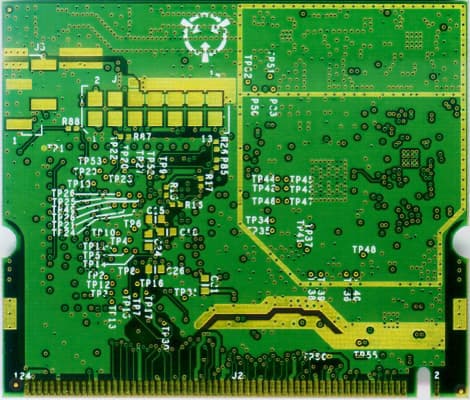
HN2WAMIG2
Nov 18, 2003802MIG2
Equipment Class
DTS - Digital Transmission System
HN2SB555-2
Sep 04, 2003SB555 Radio in 700C
Equipment Class
PCE - PCS Licensed Transmitter held to ear
HN22011B-2
Jul 28, 20032011B Radio in 700C
Equipment Class
DTS - Digital Transmission System