HN2EASYLANEASYLAN
Intermec Technologies Corporation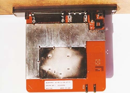
Click to zoom
Application Details
- Equipment Class
- DSS - Part 15 Spread Spectrum Transmitter
- Date of Grant
- May 08, 2002
- Application Purpose
- Original Equipment
- Date of Application
- May 08, 2002
- Equipment Note
- EASYLAN
- Frequency Range
- 2412.00000000 - 2462.00000000
- Country
- United States
Documents & Files
Document Text
Text extracted from the exhibit documents filed with the FCC. Open a document above to read the original.
Users Manual
Exhibit A: User Manual FCC ID: HN2EASYLAN EasyLAN Wireless User's Manual Intermec Technologies Corporation 6001 36th Avenue West Everett, WA 98203-9280 U.S. service and technical support: 1-800-755-5505 U.S. media supplies ordering information: 1-800-227-9947 Canadian service and technical support: 1-800-668-7043 Canadian media supplies ordering information: 1-800-268-6936 Outside U.S.A. and Canada: Contact your local Intermec service supplier. The information contained herein is proprietary and is provided solely for the purpose of allowing customers to operate and/or service Intermec manufactured equipment and is not to be released, reproduced, or used for any other purpose without written permission of Intermec. Information and specifications in this manual are subject to change without notice. 2002 by Intermec Technologies Corporation All Rights Reserved The word Intermec, the Intermec logo, INCA (under license), MobileLAN, JANUS, IRL, Trakker Antares, EZBuilder, TE 2000, Data Collection Browser, dcBrowser, Universal Access Point, UAP, Duratherm, EasyCoder, Precision Print, PrintSet, Virtual Wedge, and CrossBar are either trademarks or registered trademarks of Intermec. Throughout this manual, trademarked names may be used. Rather than put a trademark ( or ) symbol in every occurrence of a trademarked name, we state that we are using the names only in an editorial fashion, and to the benefit of the trademark owner, with no intention of infringement. There are U.S. and foreign patents pending. blank Contents iii Contents Before You Begin vii Warranty Information vii Safety Summary vii Warnings, Cautions, and Notes viii About This Manual ix Other Intermec Manuals xi Installing the EasyLAN Wireless Introducing the EasyLAN Wireless 1-3 System Requirements 1-3 Supported Operating Systems and Network Protocols 1-4 Understanding the EasyLAN Wireless 1-5 Installing the EasyLAN Wireless 1-6 Attaching the Antenna 1-6 Starting and Testing the EasyLAN Wireless 1-7 Connecting the EasyLAN Wireless to an RS-232 Serial Port 1-7 Setting Radio and Network Communications 1-8 Configuring the EasyLAN Wireless Before You Begin 2-3 Configuring the TCP/IP Parameters 2-4 Using the Web Browser Interface 2-4 Using the EasyLAN Wireless Admin Utility 2-8 Configuring the Radio Parameters 2-12 Using the Web Browser Interface 2-13 Using the EasyLAN Wireless Admin Utility 2-14 Configuring the Access and Update Passwords 2-16 Configuring the Ports 2-18 Configuring the Port Services 2-20 Configuring for the NetWare Network 2-24 Configuring the NetWare Parameters 2-25 Configuring Additional Queues 2-26 Configuring for NetBIOS 2-26 1 2 EasyLAN Wireless User’s Manual iv Configuring the DLC Parameters 2-28 Configuring for UNIX 2-29 Configuring for a Berkeley UNIX Host 2-29 Configuring for Sun Solaris 2-30 Configuring for HP/UX 2-31 Configuring for IBM AIX 2-32 Configuring for Other Systems 2-33 Managing the EasyLAN Wireless Rebooting the EasyLAN Wireless 3-3 Using the Web Browser Interface 3-3 Using the EasyLAN Wireless Admin Utility 3-6 Setting the EasyLAN Wireless to Factory Defaults 3-9 Using the Web Browser Interface 3-9 Using the EasyLAN Wireless Admin Utility 3-10 Printing a Test Label 3-10 Using the Web Browser Interface 3-10 Using the EasyLAN Wireless Admin Utility 3-11 Reloading Firmware 3-11 Viewing Ethernet Statistics 3-13 Other EasyLAN Wireless Admin Utility Functions 3-14 Configuring IP Subnets 3-14 Adding an EasyLAN Wireless 3-15 Loading Files 3-16 Saving Files 3-16 Using the Port Monitor Installing the Port Monitor 4-3 Troubleshooting the EasyLAN Wireless Troubleshooting Printing Problems 5-3 Troubleshooting Wireless Configuration Problems 5-3 Troubleshooting Network Configuration 5-4 3 4 5 Contents v Console Commands Sending the Console Commands A-3 General Commands A-5 TCP/IP Commands A-7 NetWare Commands A-8 Radio Commands A-9 A blank C39 Before You Begin vii Before You Begin This section introduces you to standard warranty provisions, safety precautions, warnings and cautions, document formatting conventions, and sources of additional product information. A documentation roadmap is also provided to guide you in finding the appropriate information. Warranty Information To receive a copy of the standard warranty provision for this product, contact your local Intermec support services organization. In the U.S. call 1-800-755-5505, and in Canada call 1-800-668-7043. If you live outside of the U.S. or Canada, you can find your local Intermec support services organization on the Intermec Web site at www.intermec.com. Safety Summary Your safety is extremely important. Read and follow all warnings and cautions in this book before handling and operating Intermec equipment. You can be seriously injured, and equipment and data can be damaged if you do not follow the safety warnings and cautions. Do not repair or adjust alone Do not repair or adjust energized equipment alone under any circumstances. Someone capable of providing first aid must always be present for your safety. First aid Always obtain first aid or medical attention immediately after an injury. Never neglect an injury, no matter how slight it seems. Resuscitation Begin resuscitation immediately if someone is injured and stops breathing. Any delay could result in death. To work on or near high voltage, you should be familiar with approved industrial first aid methods. Energized equipment Never work on energized equipment unless authorized by a responsible authority. Energized electrical equipment is dangerous. Electrical shock from energized equipment can cause death. If you must perform authorized emergency work on energized equipment, be sure that you comply strictly with approved safety regulations. EasyLAN Wireless User’s Manual viii Warnings, Cautions, and Notes The warnings, cautions, and notes in this manual use this format. Warning A warning alerts you of an operating procedure, practice, condition, or statement that must be strictly obs…
Text truncated - open the document above for the full version.
Users Manual
Exhibit O: User Manual 2 FCC ID: HN2EASYLAN Part No. 072642-001 Important EasyLAN Wireless Information! Contents For Users in the United States and Canada ........................................................................2 For Users Outside of the United States and Canada ..............................................................3 Français .................................................................................................................5 Deutsch ..................................................................................................................6 Italiano ..................................................................................................................7 Español ..................................................................................................................8 Português ...............................................................................................................9 2 For Users in the United States and Canada Place this supplement in your manual. This device complies with Part 15 of the FCC Rules and with RSS-210 of Industry Canada. Operation is subject to the following two conditions: (1) This device may not cause harmful interference, and (2) This device must accept any interference received, including interference that can cause undesired operation. Federal Communications Commission Compliance This equipment is intended for operation in a commercial environment, in compliance with the requirements for a Class A digital device, pursuant to Part 15 of the FCC Rules, and it must not be used in a residential environment; however, it has also been tested and found to comply with the more stringent requirements for a Class B device, pursuant to Part 15 of the FCC Rules. It generates, uses, and can radiate radio frequency energy. If not installed and used in accordance with the instruction manual, it may cause interference to radio communications. If this equipment causes interference, the user will be required to correct the interference at the user’s own expense. Note: To maintain compliance with FCC Rules, the input/output (I/O) cables that interconnect between the device and any peripheral must be as specified by Intermec. Operation Warning To comply with the FCC’s RF exposure requirements and minimize health hazards: The user shall stay at least 20 cm (8 in) away from the antenna of this device, when the device is in use in Intermec printers. Installation Warning To comply with the FCC’s RF exposure requirements and minimize health hazards: Printers containing this device must be installed in such a way that the user will be at least 20 cm (8 in) away from the antenna, when the device is in use. The installers should not forget that the burden of maintaining this distance is on the installer and not the user. the antennas should be installed in a manner that will comply with this requirement. Caution Changes or modifications not expressly approved by Intermec could void the user’s authority to operate this equipment. Industry Canada Compliance This Class B digital apparatus meets all requirements of the Canadian Interference-Causing Equipment Regulations. This device requires a radio license, unless it is used totally inside a building. (The user must obtain this license.) Cet appareil numérique de la classe B respecte toutes les exigences du Règlement sur le matériel brouilleur du Canada. 3 Cet appareil exige une license radio à moins d’être entièrement installé dans un bâtiment. (L’utilisateur doit obtenir cette license.) For Users Outside of the United States and Canada The Intermec product you purchased contains a Model 2126 transceiver module. This module transmits and receives data using a 2.4 GHz Direct Sequence Spread Spectrum system. In some host devices the transceiver is user accessible. If you are using such a device, please pay attention to the radio usage guidelines provided in the host device manual or getting started guide. The use of the correct antenna with correct installation is especially important for legal and efficient use of the product. In some host devices the transceiver is not user accessible. Please see the host device manual for any radio-related instructions for those products. Programming and configuration information for the transceivers is also provided in the host device documentation. Please check the Intermec Web site for additional documentation at www.intermec.com. Hereby, Intermec Technologies Corporation declares that this Model 2126 is in compliance with the essential requirements and other relevant provisions of R&TTE Directive (1999/5/EC). This product has been assessed to the following standards: • ETSI EN 300 328-2 v1.2.1 (2001-12) • ETSI EN 301 489-17 v1.1.1 (2001-09) • EN 60950:1992 (incl. Amdt. 1-4, 11) • SP/DGPT/ATAS 23 (1995-02) The original Declaration of Conformity is available on the Intermec Technologies Corporation Web site at www.intermec.com. This product transmits electromagnetic waves at 2.4 GHz frequency range. It has been tested and found compliant with U.S. (OET Guide 65) and Canadian (RSS 102) RF exposure regulations. There are no regulations covering this product type in the EU at this time. The transmitter module’s output power is 100mW or less. The products using this module are intended for business and industrial environments. They should not be used in residential environments and by children. This product is marked with this logo and uses radio frequency bands that are not harmonized throughout the European Community. The following table indicates the areas of intended use of the equipment and any known restrictions. 4 Country of Intended UseLicense YesNoRequiredRestrictions Details AustriaX BelgiumXXIf this product is used outdoors, then it is restricted to 2460 MHz to 2483.5 MHz. DenmarkX FinlandX FranceXXFrequency operation restricted to 2462 MHz to 2472 MHz. GermanyX GreeceX IrelandX ItalyX LuxembourgX The NetherlandsX PortugalX …
Text truncated - open the document above for the full version.
Attestation Statements
Exhibit J: Attestation Letter for Equivalency to PTY90148 FCC ID: HN2EASYLAN Intermec Technologies Corporation 6001 36 th Avenue West Everett, WA 98203-9280 425.356.1765 tel 425.348.2663 fax www.intermec.com April 15, 2002 Northwest EMC Labs 22975 NW Evergreen Pkwy Ste 400 Hillsboro, OR 97124 Dear Sir or Madam, Intermec Technologies Corporation hereby declares that our EasyLAN RF Print Server product (FCC ID: HN2EASYLAN) is the same transceiver as Troy Group’s Wireless Print Server (FCC ID: PTY90148). There is no hardware or software differences between the two products. Therefore all test data and technical exhibits in Troy Group’s original FCC grant application are applicable to our product as well. Please feel free to contact me, if you have any questions. Sincerely, Carl K. Turk, MSEE Sr. EMC Engineer Intermec Technologies Corp.
Attestation Statements
Exhibit K: Attestation Letter for Equipment Modification FCC ID: HN2EASYLAN Intermec Technologies Corporation 6001 36 th Avenue West Everett, WA 98203-9280 425.356.1765 tel 425.348.2663 fax www.intermec.com April 15, 2002 Northwest EMC Labs 22975 NW Evergreen Pkwy Ste 400 Hillsboro, OR 97124 Dear Sir or Madam, Intermec Technologies Corporation hereby declares that modifications required for the EMC compliance of our EasyLAN product will be incorporated in all production units. The specific modification is: the addition of copper tape along the edge of the rear RF shield near the rear I/O mounting screw. Please feel free to contact me, if you have any questions. Sincerely, Carl K. Turk, MSEE Sr. EMC Engineer Intermec Technologies Corp.
Block Diagram
Exhibit N: Frequency Block Diagram FCC ID: HN2EASYLAN
Cover Letter(s)
Northwest EMC TCB Approval Opinion Revision 05//02 INMC0015 Information about the Applicant Company Name Intermec Corp. Address 6001 36th Avenue West City, State, Zip Everett, WA 98203-9280 Requested By Carl Turk Job Number INMC0015 Model EASYLAN FCC ID HN2EASYLAN Agent Applicant Approval Type Reference Northwest EMC Technical Report – General Information Equipment Type Reference Northwest EMC Technical Report – General Information Rule Part Reference Northwest EMC Technical Report – General Information Overview This RF module is compliant with IEEE 802.11b specifications, and will be used only in the applicant’s printers as a mobile transmitter. Limited modular approval is sought for use in printer models 3400E400 and 4400. The Troy Group was previously granted certification for this same radio module (FCC ID: PTY90148). The applicant is not seeking to modify or alter the Troy Group grant in any way. A separate technical report prepared by CKC for the Troy Group application documents compliance of the radio. The applicant certifies that the radios described in both technical reports are identical. The applicant has provided attestations supporting that certification. The only changes the applicant is proposing are for three different antennas and to operate it in a group of Intermec printers. Since no other changes have been made, only those tests that are directly affected were repeated, the approval will be based upon the previous testing for all other tests. That information has been reviewed, but taken at face value as an approved product. General Comments Item The TCB 410, Application for Certification, is incorrect, it states 0.513 mW for output power, this was based upon the original application and grant. CKC and Troy group have provided correspondence that confirms the error and has committed to correct the problem. A corrected application must be submitted. Resolution A corrected Application has been submitted. Item The operation description states 1000 mW, this is not consistent with the other information provided and needs to be corrected. Resolution A corrected operation description has been submitted. Item Provide statement that provides evidence that the antenna meets the requirements of 47 CFR, 15.203. Resolution Additional information has been submitted, reference exhibit I. Northwest EMC TCB Approval Opinion Revision 05//02 INMC0015 Opinion Specification Requirements Description 15.207 Conducted Emissions Opinion: The Equipment meets the intent specified by the requirements listed above. Discussion: The Applicant has submitted test results in the form of a test report. Reference: Exhibit L Specification Requirements Description 15.247(a) Bandwidth Opinion: The Equipment meets the intent specified by the requirements listed above. Discussion: The Applicant has submitted test results in the form of a test report Reference: Exhibit L Specification Requirements Description 15.247(b) Power Output Opinion: The Equipment does not meet the intent specified by the requirements listed above. Discussion: The Applicant has submitted test results in the form of a test report. This is an RF conducted test, unless the antenna conducted test cannot be performed, this test is to be conducted using a direct connection between the antenna port of the EUT and the spectrum analyzer. No direct connect data has been provided. In addition, this application has been based upon the previous application and approval. That application and approval has been found to be incorrect. It is assumed that based upon the correspondence provided from CKC and Troy group that it was simply a mistake and that the radio has really not changed. To ensure that we can substantiate the previous test report, provide the required direct connect output power measurements. Also provide calculations supporting the previous data, demonstrating correlation between those previous measurements and the newly acquired data. Assuming these two measurements provide reasonable correlation, no additional testing will be required. Reference: Exhibit L Resolution: Output power measurements have been submitted. Additional calculations have also been submitted to support the original data in the CKC report. Reference Exhibit X for the additional information. Northwest EMC TCB Approval Opinion Revision 05//02 INMC0015 Specification Requirements Description 15.247( c ) Spurious Emissions, Antenna Conducted Opinion: The Equipment does not meet the intent specified by the requirements listed above. Discussion: The Applicant has submitted no test data for this requirement. This is an RF conducted test, unless the antenna conducted test cannot be performed, this test is to be conducted using a direct connection between the antenna port of the EUT and the spectrum analyzer. No direct connect data has been provided. Please provide antenna port conducted data as required by 47 CFR 15.247( c ). Reference: Exhibit Y Resolution: Antenna conducted spurious emissions data has been submitted. Reference Exhibit Y for the additional Specification Requirements Description 15.247( c ) Spurious Emissions, Radiated Emissions Opinion: The Equipment meets the intent specified by the requirements listed above. Discussion: The Applicant has submitted test results in the form of a test report. Reference: Exhibit R, Exhibit S, Exhibit T Specification Requirements Description 15.247(d) Power Spectral Density Opinion: The Equipment meets the intent specified by the requirements listed above. Discussion: The Applicant has submitted test results in the form of a test report Reference: Exhibit L Specification Requirements Description 15.247(e) Processing Gain Opinion: The Equipment meets the intent specified by the requirements listed above. Discussion: The Applicant has submitted test results in the form of a test report Reference: Exhibit Q Northwest EMC TCB Approval Opinion Revision 05//02 INMC0015 Specification Requirements Description 15.247(b)(4) RF Exposure…
Text truncated - open the document above for the full version.
Cover Letter(s)
Exhibit C: Request for Confidentiality Letter FCC ID: HN2EASYLAN
Cover Letter(s)
Exhibit V: Modular Approval Letter FCC ID: HN2EASYLAN NORTHWEST EMC, INC. 22975 NW Evergreen Parkway, Suite 400 Hillsboro, OR 97124 May 3, 2002 Dear Application Examiner: Intermec Corporation’s EASYLAN, FCC ID: HN2EASYLAN is seeking limited modular approval. The module will only be used in two models of printers: the 3400E400 and the 4400. The EUT meets the requirements for modular approval as detailed in FCC Public Notice DA00-1407. Compliance to each of the requirements is described below: 1. “The modular transmitter must have its own RF shielding.” The radio portion of the module is contained in its own RF shielding. The shielding is installed at the factory. Please see Exhibit F for photos of the shielding. 2. “The modular transmitter must have buffered modulation/data inputs.” The EUT has buffered data inputs to insure compliance with Part 15 requirements under conditions of excessive data rates or over-modulation. Please see Exhibit D for radio schematics of the module. 3. “The modular transmitter must have its own power supply regulation.” The EUT has its own power supply regulation to insure compliance with Part 15 requirements regardless of the quality or level of external DC supplying the module from the host unit. Please see Exhibit E for digital schematics. 4. “The modular transmitter must comply with the antenna requirements of Section 15.203 and 15.204(c).” The EUT meets the FCC antenna requirements. Please see Exhibit I for antenna information, Exhibit W for test setup photos, and Exhibits R, S, & T for the technical report. 5. “The modular transmitter must be tested in a stand-alone configuration.” The EUT was tested in a stand-alone configuration. Please see Exhibit W for test setup photos, and Exhibits R, S, & T for the technical report. The EUT was first tested for radio spurious emissions in a standalone configuration with all available antennas at low, mid, and high transmit frequencies. However, this configuration did not meet all the requirements of FCC Public Notice DA 00-1407. Although it was tested outside of a 3400 printer, it had very short (<10cm) data and power cables connecting it to the printer. After conferring with Joe Dichoso at the FCC’s OET lab, it was concluded that additional radiated scans should be made of the EUT in its typical installed configuration for each model of printer that it will be used in. It was agreed that this scan data would provide adequate justification for a “limited modular approval” for this radio in each of the printers it was tested in. The additional data is found in Exhibit T. 6. “The modular transmitter must be labeled with its own FCC ID number.” The EUT is labeled with its own FCC ID number. Please see Exhibit H for a photograph of the label and its location on the device. Since the FCC ID number will not be visible when the module is installed inside a host printer, another label with the FCC ID will be applied to the exterior of the printer. 7. “The modular transmitter must comply with any specific rule or operating requirements applicable to the transmitter and the manufacturer must provide adequate instructions along with the module to explain any such requirements.” The EUT is compliant with all applicable FCC rules. Detail instructions for maintaining compliance are given in the User Manual (see Exhibit O) . 8. “The modular transmitter must comply with any applicable RF exposure requirements.” The EUT is compliant with all applicable RF exposure requirements. RF Exposure is addressed in Section 4.5 of the technical report (see Exhibit B). RF Exposure information is provided with the antenna information (see Exhibit I). Please contact me if you have additional questions. Your attention to this matter is greatly appreciated. Best regards, Greg Kiemel, Director of Engineering Northwest EMC, Inc.
External Photos
Exhibit F: External Photos FCC ID: HN2EASYLAN
ID Label/Location Info
Exhibit H: FCC ID Label & Location FCC ID: HN2EASYLAN
Internal Photos
Exhibit G: Internal Photos FCC ID: HN2EASYLAN
Operational Description
Exhibit P: Operational Description FCC ID: HN2EASYLAN Troy Etherwind Device Description The Etherwind is an IEEE 802.11b (wireless Ethernet) compliant print-server that allows users of laptops, PDA’s, cell-phones, and other similar devices to print wirelessly using spread spectrum technology. The device utilizes 11 channels (US operation) in a DSSS modulation scheme in the 2.4GHz frequency band. These 11 channels cover 2412MHz to 2462MHz. The antenna is implemented via printed circuit etch. It transmits a maximum power of 22.4 mW compliant with FCC limitations. It has a useful range of approximately 300ft. The Etherwind is powered by common 5 Volt DC wall adapter transformers typically supplying 600mA. The Etherwind is a stand-alone device, that connects to the printer via a standard IEEE P1284 parallel connection. It can also connect to other serial devices via a DB9 standard RS-232 interface. The major components of the Etherwind are an Intersil ‘Prism’ 802.11b chip set and the associated SRAM, Flash, filter ICs and oscillators, a Motorola MC68LC302 microcontroller with its, clock oscillator, SRAM, and field upgradable FLASH memory, a high speed parallel and serial port host interface chip, and a printed circuit antenna. The Intersil chip set provides the RF radio communications functions; the MC68LC302 and associated hardware provides the printer control and server functions.
Test Report
Exhibit I: Antenna Information FCC ID: HN2EASYLAN Compliance with 47 CFR 15.247(b)(4) “Systems operating under the provisions of this section shall be operated in a manner that ensures that the public is not exposed to radio frequency energy levels in excess of the Commission's guidelines. See Sec. 1.1307(b)(1) of this chapter.” (Excerpt taken from 47 CFR 15.247(b)(4) Per 47 CFR 15.247 (b)(4), the EUT meets the requirement that it be operated in a manner that ensures the public is not exposed to radio frequency energy levels in excess of the Commission’s guidelines (ref . 47 CFR 1.1307, 1.1310, 2.1091, and 2.1093. Also OET Bulletin 65, Supplement C). The EUT will be used only in the applicant’s printers and can therefore be considered a mobile transmitter per 47 CFR 2.1091. The EUT supports the connection of only one antenna at a time. The MPE estimates are as follows: Table 1 in 47 CFR 1.1310 defines the maximum permissible exposure (MPE) for the general population as 1mW/cm 2 . The exposure level at a 20 cm distance from the EUT’s transmitting antenna is calculated using the general equation: S = (PG)/4πR 2 Where: S = power density (mW/cm 2 ) P = power input to the antenna (mW) G = linear power gain relative to an isotropic radiator R = distance to the center of the radiation of the antenna (20 cm = limit for MPE estimates) Solving for S, the maximum power densities 20 cm from the transmitting antennas are as follows: Antenna Manufacturer Antenna Type Antenna Part No. Transmit Frequency Max Peak Conducted Output Power Antenna Gain Power Density @ 20 cm Maximum Permitted Power Density (MHz) (mW) (dBi) (mW/cm 2 ) (mW/cm 2 ) Cushcraft omni 63363 2400 52 5 0.033 1 Centurion tuned dipole 66147 2400 52 1 0.013 1 Centurion patch 67262 2400 52 5 0.033 1 Intermec Technologies Corporation 6001 36 th Avenue West Everett, WA 98203-9280 425.356.1765 tel 425.348.2633 fax www.intermec.com May 7, 2002 To Whom It May Concern: Intermec complies with the unique connector requirement of FCC Part 15.203 by using a modified TNC connector. As can be seen in the following drawings the dimensions of the teflon insulator inside the metal sleeve are different in our custom TNC connector (first drawing) than the standard TNC connector (second drawing). This makes it impossible to properly mate our custom TNC connector with a standard polarized (reversed gender) TNC connector, since the insulators would be destroyed if the connectors are forced. If you have any questions regarding this product, please feel free to contact me (phone: 425 356 1765, fax: 425 348 2633, email: [email protected]). Sincerely, Carl K. Turk, MSEE Sr. EMC Engineer Intermec Technologies Corp.
Test Report
Page 1 of 52 Report No: FC01-063 TROY GROUP, INC. WIRELESS AND CONDUCTIVITY DIVISION TEST REPORT FOR THE WIRELESS PRINT SERVER, ETHERWIND FCC PART 15 SUBPART C SECTIONS 15.207, 15.209 AND 15.247 COMPLIANCE DATE OF ISSUE: SEPTEMBER 19, 2001 PREPARED FOR: Troy Group, Inc. Wireless and Conductivity Division 1692 Browning Irvine, CA 92606-4809 PREPARED BY: Mary Ellen Clayton CKC Laboratories, Inc. 5473A Clouds Rest Mariposa, CA 95338 P.O. No.: W.O. No.: 005008-00 76953 Date of test: August 23-28, 2001 Report No.: FC01-063 This report contains a total of 52 pages and may be reproduced in full only. Partial reproduction may only be done with the written consent of CKC Laboratories, Inc. Page 2 of 52 Report No: FC01-063 TABLE OF CONTENTS Administrative Information ............................................................................................. 4 Summary of Results......................................................................................................... 5 Modifications Required for Compliance ......................................................................... 5 Approvals......................................................................................................................... 5 Equipment Under Test (EUT) Description...................................................................... 6 Equipment Under Test..................................................................................................... 6 Peripheral Devices ........................................................................................................... 6 15.33 Frequency Range Tested ....................................................................................... 7 Radiated Emissions ............................................................................................. 7 Conducted Emissions .......................................................................................... 7 EUT Operating Frequency............................................................................................... 7 Temperature and Humidity During Testing .................................................................... 7 Report of Measurements.....................…
Text truncated - open the document above for the full version.
Contact Information
Applicant
Brian Rudick(VP & GC, Honeywell Scanning & Mobility)
Technical Contact
Northwest EMC, Inc.Greg V Kiemel
[email protected]503-844-4066
22975 NW Evergreen Parkway · Hillsboro, Oregon · United States
Non-Technical Contact
Northwest EMC, Inc.Vicki Albertson
[email protected]503-844-4066
Test Firm
Northwest EMC, Inc.Greg Kiemel
Technical Specifications
| # | Rule Parts | Frequency Range | Power Output |
|---|---|---|---|
| 1 | 15C | 2.41 GHz - 2.46 GHz | 22.40 mW |
Other Applications from Intermec Technologies Corporation

HN2-BTM311
Nov 23, 2004BTM311
Equipment Class
DTS - Digital Transmission System
HN2-802CF13E
Nov 07, 2004EasyLAN
Equipment Class
DTS - Digital Transmission System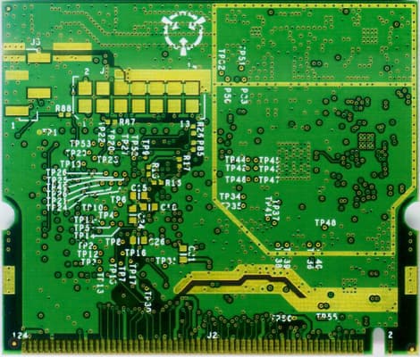
HN2WAMIG2
Nov 18, 2003802MIG2
Equipment Class
DTS - Digital Transmission System
HN2SB555-2
Sep 04, 2003SB555 Radio in 700C
Equipment Class
PCE - PCS Licensed Transmitter held to ear
HN22011B-2
Jul 28, 20032011B Radio in 700C
Equipment Class
DTS - Digital Transmission System