HN2MPCI3A-20MPCI3A-20
Intermec Technologies Corporation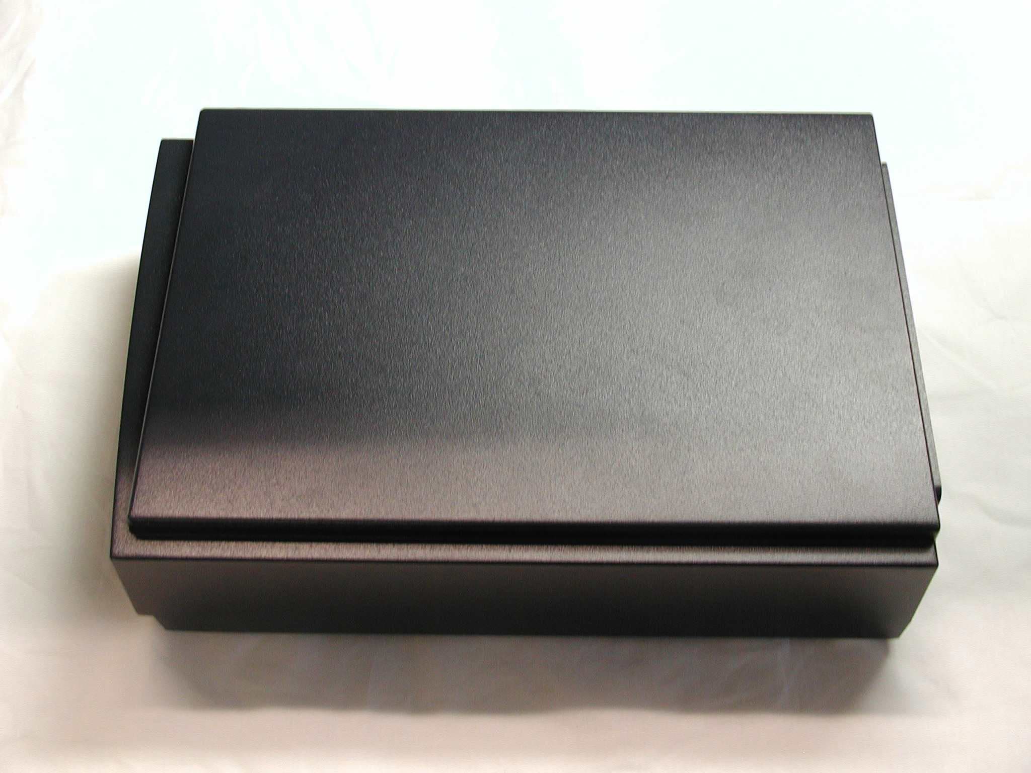
Click to zoom
Application Details
- Equipment Class
- DTS - Digital Transmission System
- Date of Grant
- Aug 15, 2002
- Application Purpose
- Original Equipment
- Date of Application
- Aug 15, 2002
- Equipment Note
- MPCI3A-20
- Frequency Range
- 2412.00000000 - 2462.00000000
- Country
- United States
Documents & Files
Document Text
Text extracted from the exhibit documents filed with the FCC. Open a document above to read the original.
Users Manual
Exhibit J: User Manual-MPCI3A-20 FCC ID: HN2MPCI3A-20 Part No. 072870-001 1 Important MPCI3A-20 Information! Contents For Users in the United States and Canada.......................................................................... 2 For Users Outside of the United States and Canada ............................................................ 3 Pour les utilisateurs en dehors du Canada et des Etat-unis ................................................... 4 Für Benutzer außerhalb von Kanada und den Vereinigten Staaten ....................................... 6 Per gli utenti al di fuori del Canada o degli Stati Uniti ........................................................ 7 Para Usuarios Fuera de Canada o de los Estados Unidos...................................................... 8 Para Usuários Fora do Canadá ou dos Estados Unidos ........................................................ 9 2 For Users in the United States and Canada Place this supplement in your manual. This device complies with Part 15 of the FCC Rules and with RSS-210 of Industry Canada. Operation is subject to the following two conditions: (1) This device may not cause harmful interference, and (2) This device must accept any interference received, including interference that can cause undesired operation. Federal Communications Commission Compliance This equipment is intended for operation in a commercial environment, in compliance with the requirements for a Class A digital device, pursuant to Part 15 of the FCC Rules, and it must not be used in a residential environment; however, it has also been tested and found to comply with the more stringent requirements for a Class B device, pursuant to Part 15 of the FCC Rules. It generates, uses, and can radiate radio frequency energy. If not installed and used in accordance with the instruction manual, it may cause interference to radio communications. If this equipment causes interference, the user will be required to correct the interference at the user’s own expense. Warning Avertissement Operation Warning The user shall stay at least 20 cm (8 in) away from the antenna of this device, when the device is in use in access points and other hosts, where higher gain antennas may be used. Warning Avertissement Installation Warning To comply with the FCC’s RF exposure requirements and minimize health hazards: Host devices with higher gain antennas such as access points must be installed in such a way that the user will be at least 20 cm (8 in) away from the antenna, when the device is in use. The installers should not forget that the burden of maintaining this distance is on the installer and not the user. the antennas should be installed in a manner that will comply with this requirement. Caution Conseil Changes or modifications not expressly approved by Intermec could void the user’s authority to operate this equipment. Note To maintain compliance with FCC Rules, the input/output (I/O) cables that interconnect between the device and any peripheral must be as specified by Intermec. Industry Canada Compliance This Class B digital apparatus meets all requirements of the Canadian Interference-Causing Equipment Regulations. This device requires a radio license, unless it is used totally inside a building. (The user must obtain this license.) 3 Cet appareil numérique de la classe B respecte toutes les exigences du Règlement sur le matériel brouilleur du Canada. Cet appareil exige une license radio à moins d’être entièrement installé dans un bâtiment. (L’utilisateur doit obtenir cette license.) Agency Approvals This device is UL Listed and CSA Certified. For Users Outside of the United States and Canada The Intermec product you purchased contains a Model MPCI3A-20 transceiver module. This module transmits and receives data using a 2.4 GHz Direct Sequence Spread Spectrum system. In some host devices the transceiver is user accessible. If you are using such a device, please pay attention to the radio usage guidelines provided in the host device manual or getting started guide. The use of the correct antenna with correct installation is especially important for legal and efficient use of the product. In some host devices the transceiver is not user accessible. Please see the host device manual for any radio-related instructions for those products. Programming and configuration information for the transceivers is also provided in the host device documentation. Please check the Intermec Web site for additional documentation at www.intermec.com. Hereby, Intermec Technologies Corporation declares that this Model MPCI3A-20 is in compliance with the essential requirements and other relevant provisions of R&TTE Directive (1999/5/EC). This product has been assessed to the following standards: • ETSI EN 300 328-2 v1.2.1 (2001-12) • ETSI EN 301 489-17 v1.1.1 (2001-09) • EN 60950:1992 (incl. Amdt. 1-4, 11) The original Declaration of Conformity is available on the Intermec Technologies Corporation Web site at www.intermec.com. This product transmits electromagnetic waves at 2.4 GHz frequency range. It has been tested and found compliant with U.S. (OET Guide 65) and Canadian (RSS 102) RF exposure regulations. There are no regulations covering this product type in the EU at this time. The transmitter module’s output power is 32mW. The products using this module are intended for business and industrial environments. They should not be used in residential environments and by children. 0981 This product is marked with this logo and uses radio frequency bands that are not harmonized throughout the European Community. 4 The following table indicates the areas of intended use of the equipment and any known restrictions. Country of Intended UseLicense YesNoRequiredRestrictionsDetails AustriaX BelgiumXXIf this product is used outdoors, then it is restricted to 2460 MHz to 2483.5 MHz. DenmarkX FinlandX FranceXXFrequency operation restricted to 2462 MHz to 2472 MHz. GermanyX GreeceX IrelandX ItalyX Luxembou…
Text truncated - open the document above for the full version.
Users Manual
Exhibit J: User Manual-WA21 & WA22 FCC ID: HN2MPCI3A-20 Part No. 072831-001 1 Important WA21/WA22 Information! Contents For Users in the United States and Canada.......................................................................... 2 For Users Outside of the United States and Canada ............................................................ 3 Pour les utilisateurs en dehors du Canada et des Etat-unis ................................................... 3 Für Benutzer außerhalb von Kanada und den Vereinigten Staaten ....................................... 4 Per gli utenti al di fuori del Canada o degli Stati Uniti ........................................................ 4 Para Usuarios Fuera de Canada o de los Estados Unidos...................................................... 5 Para Usuários fora do Canadá ou dos Estados Unidos ......................................................... 5 .............................................................................................. 6 2 For Users in the United States and Canada Place this supplement in your manual. Federal Communications Commission Compliance This device complies with Part 15 of the FCC Rules. Operation is subject to the following two conditions: (1) This device may not cause harmful interference, and (2) This device must accept any interference received, including interference that can cause undesired operation. This equipment is intended for operation in a commercial environment, in compliance with the requirements for a Class A digital device, pursuant to Part 15 of the FCC Rules, and it must not be used in a residential environment; however, it has also been tested and found to comply with the more stringent requirements for a Class B device, pursuant to Part 15 of the FCC Rules. It generates, uses, and can radiate radio frequency energy. If not installed and used in accordance with the instruction manual, it may cause interference to radio communications. If this equipment causes interference, the user will be required to correct the interference at the user’s own expense. Caution Conseil Changes or modifications not expressly approved by Intermec could void the user’s authority to operate this equipment. Caution Conseil Regulatory statements relating to the transceivers contained in this product are in a separate manual supplement accompanying the transceiver. Note In order to maintain compliance with FCC Rules, the input/output (I/O) cables that interconnect between the device and any peripheral must be as specified by Intermec. Industry Canada Compliance This Class B digital apparatus meets all requirements of the Canadian Interference-Causing Equipment Regulations. Cet appareil numérique de la classe B respecte toutes les exigences du Réglement sur le matériel brouilleur du Canada. Additional EMI/RFI Compliance This device meets the Class B limit requirements of CISPR 22. Safety Agency Approvals This device is UL and cUL Listed (UL 1950/C22.2 #950) and TÜV GS Licensed (EN 60950) for safety. 3 For Users Outside of the United States and Canada Place this supplement in your manual. This product complies with EN55022, EN55024, and EN 60950 as required by the EMC Directive 89/336/EEC as amended by 92/31/EEC and by the Low Voltage Directive 73/23/EEC as amended by 93/68/EEC. Safety Agency Approvals This device is UL and cUL Listed (UL 1950/C22.2 #950) and TÜV GS Licensed (EN 60950) for safety. Additional EMI/RFI Compliance This device meets the Class B limit requirements of CISPR 22. This device complies with AS/NZS 3548 and other applicable rules under the Australian EMC framework. Pour les utilisateurs en dehors du Canada et des Etat-unis Veuillez placer ce supplément dans votre manuel. Déclaration de conformité européenne Ce produit est conformé aux normes EN55022, EN55024 et EN 60950 tel qu’exigé par la directive de l’EMC nº 89/336/CEE amendée par l’article 92/31/CEE et par la directive sur la basse tension nº 73/23/CEE amendée par l’article 93/68/CEE. Approbations d'agences pour la sécurité Cet appareil fait partie de la liste UL et cUL (UL 1950/C22.2 n° 950) et il est sous licence TÜV GS (EN 60950) en termes de sécurité. Conformité additionelle à la norme EMI/RFI Cet appareil respecte les limites imposées pour la Classe B par le CISPR 22. 4 Für Benutzer außerhalb von Kanada und den Vereinigten Staaten Legen Sie diese Ergänzung in Ihr Handbuch. Europäische Übereinstimmungserklärung Dieses Produkt entspricht EN55022, EN55024, und EN 60950 in Übereinstimmung mit der EMC-Richtlinie 89/336/EWG, abgeändert durch 92/31/EWG, und der Richtlinie für Niederspannung 73/23/EWG, abgeändert durch 93/68/EWG. Sicherheitszulassungen durch Prüfstellen Dieses Gerät ist in die UL- und die c-UL-Liste (UL 1950/C22.2 Nr. 950) aufgenommen und vom TÜV GS (EN 60950) gemäß der Sicherheitsnorm lizenziert. Zusätzliche Elektromagnetische Störung-Übereinstimmung Dieses Gerät stimmt mit den Grenzbestimmungen der Klasse B von CISPR 22 überein. Per gli utenti al di fuori del Canada o degli Stati Uniti Si prega di collocare questo supplemento nel manuale. Dichiarazione europea di conformità Questo prodotto è conforme a EN55022, EN55024, e EN 60950 come richiesto dalla Direttiva EMC 89/336 CEE, modificata dalla 92/31/CEE e dalla Direttiva sulla bassa tensione 73/23/CEE, modificata dalla 93/68/CEE. Approvazioni relative alla sicurezza Questo prodotto è conforme agli standard di sicurezza UL e cUL (UL 1950/CC22.2 n.950) e TÜV GS (EN 60950). Ulteriore conformità con EMI/RFI Questo dispositivo è conforme ai limiti stabiliti in CISPR 22 per la Classe B. 5 Para Usuarios Fuera de Canada o de los Estados Unidos Por favor, coloque este suplemento dentro de su manual. Declaración de conformidad europea Este producto cumple con las normas EN55022, EN55024, y EN 60950 de acuerdo a lo establecido por la directiva de EMC 89/336/CEE corregida por 92/31/CEE y por la directiva referente al bajo voltaje 73/23/CEE corregida por 93/68/CEE. Aprobación de organismos …
Text truncated - open the document above for the full version.
Cover Letter(s)
Exhibit K: Request for Confidentiality FCC ID: HN2MPCI3A-20
Cover Letter(s)
Northwest EMC TCB Approval Opinion Revision 05/9/02 INMC0023 Information about the Applicant Company Name Intermec Corp. Address 6001 36th Avenue West City, State, Zip Everett, WA 98203-9280 Requested By Carl Turk Job Number INMC0023 Model MPCI3A-20 FCC ID HN2MPCI3A-20 Agent Applicant Approval Type Reference Northwest EMC Technical Report – General Information Equipment Type Reference Northwest EMC Technical Report – General Information Rule Part Reference Northwest EMC Technical Report – General Information Overview This 802.11b, Direct Sequence, Spread Spectrum Radio will be used only in two Intermec Access Points. The approval covers use in both the Model WA 21 and Model WA 22 Access Points. Only those antenna listed below may be used with this device. The device is intended only for Professional installations as specified by the installation manual. The device meets the requirements for transmitting antennas of directional gain greater than 6 dBi as specified in 15.247 (b)(3). Part Number: 063363 Omni 5 dBi Gain Part Number: 063365 Yagi 15 dBi Part Number: 063366 Flat Panel 14 dBi Part Number: 065349 Omni 9 dBi Part Number: 066147 Omni 1 dBi Part Number: 067261 Omni 3 dBi Part Number: 067262 Panel 5 dBi Part Number: 067263 Flat Panel 9 dBi General Comments Item Resolution Item Resolution Item Resolution Northwest EMC TCB Approval Opinion Revision 05/9/02 INMC0023 Opinion Specification Requirements Description 15.207 Conducted Emissions Opinion: The Equipment meets the intent specified by the requirements listed above. Discussion: The Applicant has submitted test results in the form of a test report. Reference: Exhibit T Specification Requirements Description 15.247(a) Bandwidth Opinion: The Equipment meets the intent specified by the requirements listed above. Discussion: The Applicant has submitted test results in the form of a test report Reference: Exhibit M Specification Requirements Description 15.247(b) Power Output Opinion: The Equipment meets the intent specified by the requirements listed above. Discussion: The Applicant has submitted test results in the form of a test report Reference: Exhibit N Specification Requirements Description 15.247( c ) Spurious Emissions, Antenna Conducted Opinion: The Equipment meets the intent specified by the requirements listed above. Discussion: The Applicant has submitted test results in the form of a test report Reference: Exhibit P, Exhibit L Specification Requirements Description 15.247( c ) Spurious Emissions, Radiated Emissions Opinion: The Equipment meets the intent specified by the requirements listed above. Discussion: The Applicant has submitted test results in the form of a test report. Reference: Exhibit Q, Exhibit L Northwest EMC TCB Approval Opinion Revision 05/9/02 INMC0023 Specification Requirements Description 15.247(d) Power Spectral Density Opinion: The Equipment meets the intent specified by the requirements listed above. Discussion: The Applicant has submitted test results in the form of a test report Reference: Exhibit O Specification Requirements Description 15.247(b)(4) RF Exposure Opinion: The Equipment meets the intent specified by the requirements listed above. Discussion: The Applicant has submitted MPE estimates demonstrating compliance. Reference: Exhibit R
External Photos
Exhibit D: External Photos FCC ID: HN2MPCI3A-20
ID Label/Location Info
Exhibit A: FCC ID Label and Location FCC ID: HN2MPCI3A-20 WN-5MP01 and MPCI3A-20 Regulatory Labels WN-5MP01 and MPCI3A-20 Regulatory Labels (close-up)
ID Label/Location Info
Exhibit A: FCC ID Label and Location Revised 10-21-02 FCC ID: HN2MPCI3A-20
ID Label/Location Info
Labeling scheme for two FCC ID HN2WN-5MP01 Labeling scheme for two FCC ID HN2MPCI3A-20 Labeling scheme for one FCC ID HN2MPCI3A-20 Labeling scheme for one FCC ID HN2WN-5MP01 Labeling scheme for one FCC ID HN2WN-5MP01 and one FCC ID HN2MPCI3A-20
Internal Photos
Exhibit E: Internal Photos FCC ID: HN2MPCI3A-20
Internal Photos
Exhibit E: Internal Photos FCC ID: HN2MPCI3A-20
Operational Description
Exhibit I: Operational Description FCC ID: HN2MPCI3A-20 DESCRIPTION OF THE Orinoco 2.4 GHz BLOCKDIAGRAM The various parts of the Blockdiagram are numbered and an explanation is given of these blocks. First the transmitter will be described: A) Digital Signal Processor. (22) Function : Generate spreaded signal with an Barker sequence of 11, the original raw data rate of two Megabits is transformed to a symbol rate of one MegaBaud and multiplied with eleven and modulated with a DQPSK ( Differential Quadrature Phase Shift Keying ) Modulation. The unfiltered data comes out of I and Q and goes to the up/down mixer (6) B) The above signals are mixed in (6) in a so called quadrature modulator with the Intermediate Frequency ( IF) of 352 MHz. C) The upmixer is fed by the VCO of 704 MHz, which is divided by 2 to 352 MHz. D) The SAW ( 8 ) filters all unwanted mixing products, such that only the 352 MHz band remains. E) This signal goes into the RF upmixer ( 9) SA2420 were it is mixed with the RF VCO with a range of 2050 to 2150 MHz. F) The Rx/Tx switch (17) brings the signal to the variable attenuator (10 ), where the output level is controlled. G) The signal is fed through a 2.4- 2.5 GHz bandpass filter (11) to remove all unwanted mixer products, and thus to get a clean signal for further processing. H) The signal is amplified in (12), with approx 23 dB to an output level of approx. 15 dBm I) This signal goes to the special connector. J) The output power is controlled with a so called power feed back loop (15) in which the output power is compared with a DAC value from (10) Receiver functions. K) The receive signal enters the antenna passes the RX/TX switch (14) and (13) this is set to RX mode. L) The signal goes through the 2.4 GHz filter (16) to remove all unwanted spectral components in order to deliver a clean signal for the receiver. M) A Low Noise Amplifiers (LNA) (in 9) is used to amplify the weak signal to a level fitted for down mixing. N) The AGC (27) can amplify or attenuate the signal according to the Digital signal processor required input with a step size of 26 dB. O) Again the Rx/Tx switch in the Rx mode is passed and also the same filter as in transmit mode ( 18). P) The down mixer (9) mixes the 2.4 GHz with the 2.1 GHz to the 352 MHz IF. Q) The signal of 352 MHz is amplified again (9) and filtered by a SAW filter (19) to give a clean signal for the second mixer. R) The Downmixer (6) mixes the 352 MHz signal down to the I and Q signals, also the auto gain control can increase the level to the required level via line 20. S) The very low amplitude baseband I and Q signal is amplified in the AMPs (6) to a level fitted for the Analog to Digital converters (22), which make it a proper signal for the digital signal processor. T) The digital signal processor (22) removes the spreading as present on the signal with a so called autocorrelation function. The resulting output of the processor is a received data rate of 2 Megabits. VCO , PLL and OSC. U) These three form one entity to generate a single tone signal for down mixing. There are two of these blocks available, one for the IF LO (7 and 6 ) (352MHz ) and one for the RF LO (25 and 26) of 2050 to 2150 MHz. V) All the PLL’s and the processor (2) have one reference Crystal of 22 MHz (4) with an accuracy of 25 ppm. General circuits: W) Antenna Diversity. Depending on the signal strength and signal quality the Digital processor (22) can select between two antenna’s which gives the best signal. This is done initial during the training sequence in the received signal. X) Automatic Gain control. Depending on the signal strength and signal quality the Digital processor (22) can choose to increase or decrease the signal level at the digital input, this is done by reducing or increasing the gain in the receiver via the LNA-AGC (in 9). Y) The Signal processor (22) can read via the MAC (2) the registers for programming all Z) The MAC is used to do the handshaking with the miniPCI bridge chip bus (1 ) and handling the IEEE protocol. Also used to load the PLL frequencies and dividers, also used to interface to the Eeprom which contains all parameters for the PLL’s and the Callcode Blockdiagram description of the Lucent 2.4 GHz Orinoco, miniPCI card Guus Jansen Aug 16, 2000
Operational Description
Exhibit H: Antenna Information FCC ID: HN2MPCI3A-20 All the antennas described in this exhibit use a reverse polarity TNC connector that satisfies the requirements of 47CFR 15.203 2.4 GHz antennas for the 802.11b radio Intermec Part Number Min. Freq. (GHz) Max. Freq. (GHz) Style Max. Gain 063363 2.4 2.5 Omni 5 dBi 063365 2.4 2.5 Yagi 15 dBi 063366 2.4 2.5 Flat Panel 14 dBi 065349 2.4 2.5 Omni 9 dBi 066147 2.4 2.5 Omni 1 dBi 067261 2.4 2.5 Mini Omni 3 dBi 067262 2.4 2.5 Flat Panel 5 dBi 067263 2.4 2.5 Flat Panel 9 dBi Positioning Antennas C 2 Positioning Antennas C-3 C This appendix provides information about positioning the antennas for the Wireless Access Points. Specific guidelines for antenna separation are provided for those configurations that have multiple antennas. Antenna Placement Guidelines Every environment is unique with different obstacles and materials. Therefore, the exact range that you will achieve with your UAP is difficult to determine. Intermec recommends that you allow an Intermec-certified RF specialist to perform a site survey before you install a wireless network. For more information on site surveys, contact your local Intermec representative. Radio signals may reflect off some obstacles and be absorbed by others. For example, two radios may achieve up to 305 meters (1,000 feet) of range if positioned outdoors within line of sight, with no obstacles between them. However, the same two units may only achieve up to 152 meters (500 feet) of range when the RF signal has to travel through items such as cubicles. If the signal must penetrate office walls, the signal range may decrease to 91 meters (300 feet). Proper antenna placement can help improve range. If you are interested in antenna options, contact your Intermec representative about antenna kits. Here are some general guidelines for positioning antennas: • Place the antenna as high as possible. In an office environment, try to place it above cubicle walls. • Do not place a sheet of metal (such as a filing cabinet) between two antennas. The following sections provide detailed information about antenna placement for those UAPs that can have more than one antenna. Positioning the Antennas for a 2.4 GHz OpenAir WAP Because the 2.4 GHz OpenAir WAP has two radios installed in the device, you need to pay particular attention to the placement of the two antennas. Proper positioning of the antennas is critical for proper functioning of the WAP. You attach antenna cables to the 2110, and then attach the cables to antennas mounted in your work environment. There are two types of Intermec-recommended antennas you can use: • Omni • Directional You can position the antennas in one of three ways: • Horizontal. Both antennas are mounted in the same plane (at the same height). • Stacked. One antenna is mounted directly above the other. • Angled. The two antennas are mounted some distance apart and at different heights. 21XX Universal Access Point Technical Reference Manual C-4 You can use either two omni antennas, two directional antennas, or one omni antenna and one directional antenna. The following table shows the MINIMUM distance that must exist between the two antennas. Position 2 Omni Antennas 2 Directional Antennas 1 Omni, 1 Directional Antenna Horizontal 3dBi omni, 3 meters (10 feet) 6dBi omni, 6.1 meters (20 feet) 9dBi omni, 12.2 meters (40 feet) 3 meters (10 feet) 6.1 meters (20 feet) Stacked .6 meters (2 feet) (does not apply) .6 meters (2 feet) Angled 1.1 meters (3.5 feet) vertically and 7.3 meters (24 feet) horizontally .6 meters (2 feet) vertically and 3 meters (10 feet) horizontally .6 meters (2 feet) vertically and 6.1 meters (20 feet) horizontally Note these additional points about positioning your antennas: • Intermec recommends that you mount omni antennas so they point down. • If you are using one omni antenna and one directional antenna, you should mount the directional antenna so that it points away from the omni antenna. • If you are using one omni antenna and one directional antenna in the stacked position, you must mount the directional antenna above the omni antenna. • If you are using two directional antennas, you must mount them back-to-back. Positioning the Antennas for an IEEE 802.11 DS Radio The IEEE 802.11 DS radio features antenna diversity, which means that each radio has two antennas. One antenna functions as a receive antenna and the other antenna functions as both a transmit and a receive antenna. Note that only one antenna is used at a time in a diversity system. On an IEEE 802.11 DS radio, the centermost antenna is the antenna that both transmits and receives radio signals. If you attach only one antenna to the IEEE 802.11 DS radio, you should attach it to the centermost antenna connector for that radio card. If you are using two antennas for your IEEE 802.11 DS WAP, placement of the antennas is critical because each antenna has a particular function. Antennas placed too close together may cause interference with each other. Antennas placed too far apart may not be able to establish two-way communications with other radios. To achieve optimum placement for the two antennas, you must place the transmit/receive antenna so that it is within range of all the radios that the receive-only radio can hear. Positioning Antennas C-5 C Note these important points about antenna placement for an IEEE 802.11 DS radio: • Use the recommended antenna separation for placement of either omni or directional antennas. • Position directional antennas so they point in the same direction. • Follow the recommended antenna separation precisely when using the closest distances. Movement of as little as 3.05 centimeters (1.2 in) may strongly affect performance. • Position the antennas so that both antennas are within range of the radios they need to communicate with. • Do not position the two antennas around a corner or so that a wall is between them. The recommended antenna separation is listed in the following tabl…
Text truncated - open the document above for the full version.
Operational Description
MobileLAN WA21 Radio Replacement Instructions 1 About the Radio Upgrade Kit In the MobileLAN access WA21, you may need to add a second radio, replace a malfunctioning radio, or remove one type of radio and replace it with another type of radio. These instructions explain how to add or replace a radio, how to reconfigure the configuration matrix string, and how and where to apply the new labels. At the end of these instructions you can find some troubleshooting information. Note: The country code is programmed into the radio at the factory. The country code should always remain the same in an access point. You should not upgrade an access point with a radio with a different country code. There are three radio upgrade kits that you can order: 802.11b Radio (P/N RWA21A704) 802.11a Full-Range Radio (P/N RWA21A904) 802.11a Mid-Range Radio (P/N RWA21A954) • Mini-PCI radio card • Mini-PCI radio card • Mini-PCI radio card • Retainer clip • Retainer clip • Retainer clip • RF certification label • RF certification label • RF certification label • Radio upgrade kit label • Radio upgrade kit label • Radio upgrade kit label • Antenna cable assemblies (2) • Antenna cable assemblies (2) • Antenna cable assemblies (2) • Antennas (2) To maintain the IP54 rating, Intermec recommends that you also replace this part: • Gasket (P/N 065194-002) You need these tools: • Torx T20 (to open the access point) • Ratchet with 16 mm (5/8 in) socket • 16 mm (5/8 in) open-ended socket wrench 2 MobileLAN WA21 Radio Replacement Instructions • Calibrated torque screwdriver You may also need these tools: • Scissors (to trim the RF certification label) Integrated circuits on the printed circuit board (PCB) in the access point are very sensitive to damage by electrostatic discharge (ESD). Prevent ESD by always wearing skin contact ground straps firmly attached to the equipment metal base assembly when working inside the access point. Never open the unit package without safeguarding the entire work area with ESD protection. Failure to comply may result in damage to PCB components. Opening the Access Point Note: Opening this product can result in voiding the warranty. Only Intermec service personnel should perform radio upgrades and replacements. 1 Before you replace or add a radio, note the configuration settings. 2 Turn the access point over so it rests on its top cover. 3 Unscrew the two thumbscrews on the cable access door and remove the door. 4 Disconnect all cables. 5 Remove the seven screws that connect the top and bottom of the access point cover, and then turn the access point over so it rests on its feet. MobileLAN WA21 Radio Replacement Instructions 3 6 Slowly separate the cover from the chassis by tilting it from the back and disconnect the LED flex assembly from the main printed circuit board (PCB). 2100M.049 LED assembly 7 Completely remove the top cover. 8 Carefully remove the gasket. 2100M.045 4 MobileLAN WA21 Radio Replacement Instructions Removing a Radio and the Antenna Cable Assembly If you are replacing a malfunctioning radio or if you are replacing one type of radio with another type of radio, you must remove the existing radio and antenna cable assembly. To remove a radio 1 Lift the antenna cables off the radio. Retaining Clip Radio Antenna cable Antenna socket WA21I001.eps 2 Carefully pry one end of the retainer clip off the radio and remove the clip. 3 Pull apart the spring clips on either side of the radio until the radio tilts up. Gently rock the radio back and forth while pulling it out to remove it from the mini-PCI connector. WA21I009.eps Retaining clip (2 places)sO 4 Unscrew the antennas for the radio you are removing. MobileLAN WA21 Radio Replacement Instructions 5 5 Use the open-ended socket…
Text truncated - open the document above for the full version.
Contact Information
Applicant
Brian Rudick(VP & GC, Honeywell Scanning & Mobility)
Technical Contact
Northwest EMC, Inc.Greg V Kiemel
[email protected]503-844-4066
22975 NW Evergreen Parkway · Hillsboro, Oregon · United States
Non-Technical Contact
Northwest EMC, Inc.Vicki L Albertson
[email protected]503-844-4066
Test Firm
Northwest EMC, Inc.Greg Kiemel
Technical Specifications
| # | Rule Parts | Frequency Range | Power Output |
|---|---|---|---|
| 1 | 15C | 2.41 GHz - 2.46 GHz | 21.50 mW |
Other Applications from Intermec Technologies Corporation

HN2-BTM311
Nov 23, 2004BTM311
Equipment Class
DTS - Digital Transmission System
HN2-802CF13E
Nov 07, 2004EasyLAN
Equipment Class
DTS - Digital Transmission System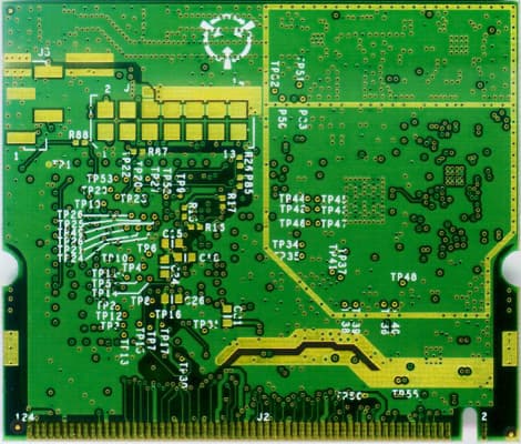
HN2WAMIG2
Nov 18, 2003802MIG2
Equipment Class
DTS - Digital Transmission System
HN2SB555-2
Sep 04, 2003SB555 Radio in 700C
Equipment Class
PCE - PCS Licensed Transmitter held to ear
HN22011B-2
Jul 28, 20032011B Radio in 700C
Equipment Class
DTS - Digital Transmission System