HN2RM182-242.4 GHz FHSS Limited Module Approval
Intermec Technologies Corporation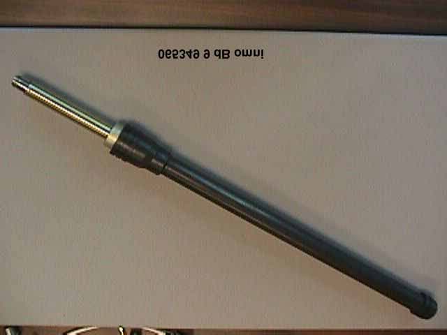
Click to zoom
Application Details
- Equipment Class
- DSS - Part 15 Spread Spectrum Transmitter
- Date of Grant
- May 14, 2000
- Application Purpose
- Original Equipment
- Date of Application
- Apr 10, 2000
- Equipment Note
- 2.4 GHz FHSS Limited Module Approval
- Frequency Range
- 2402.00000000 - 2480.00000000
- Country
- United States
Documents & Files
Document Text
Text extracted from the exhibit documents filed with the FCC. Open a document above to read the original.
Users Manual
P/N XXXXXX-001 Important RM182 Information! Contents For Users in the United States and Canada....................................................................................2 For Users Outside of the United States or Canada........................................................................4 Français.............................................................................................................................................5 Deutsch...............................................................................................................................................6 Italiano...............................................................................................................................................7 Español.............................................................................................................................................8 2 RM182 Manual Supplement For Users in the United States and Canada Place this supplement in your manual. This device complies with Part 15 of the FCC Rules and with RSS-210 of Industry Canada. Operation is subject to the following two conditions: (1) This device may not cause harmful interference, and (2) This device must accept any interference received, including interference that can cause undesired operation. Federal Communications Commission Compliance This equipment is intended for operation in a commercial environment, in compliance with the requirements for a Class A digital device, pursuant to Part 15 of the FCC Rules, and it must not be used in a residential environment; however, it has also been tested and found to comply with the more stringent requirements for a Class B device, pursuant to Part 15 of the FCC Rules. It generates, uses, and can radiate radio frequency energy. If not installed and used in accordance with the instruction manual, it may cause interference to radio communications. If this equipment causes interference, the user will be required to correct the interference at the user’s own expense. Note: In order to maintain compliance with FCC Rules, the input/output (I/O) cables that interconnect between the device and any peripheral must be as specified by Intermec. Operation Warning: To comply with the FCC’s RF exposure requirements and minimize health hazards: The user shall not touch the antenna of this device, when the device is in use in handheld and vehicle mount terminals, where low gain antennas are used. The user shall stay at least 20 cm (8 inches) away from the antenna of this device, when the device is in use in access points and other hosts , where higher gain antennas may be used. Installation Warning: To comply with the FCC’s RF exposure requirements and minimize health hazards: Host devices with higher gain antennas such as access points must be installed in such a way that the user will be at least 20 cm (8 inches) away from the antenna, when the device is in use. Caution Changes or modifications not expressly approved by Intermec could void the user’s authority to operate this equipment. 3 Industry Canada Compliance This Class B digital apparatus meets all requirements of the Canadian Interference- Causing Equipment Regulations. This device requires a radio license, unless it is used totally inside a building. (The user must obtain this license.) Cet appareil numérique de la classe B respecte toutes les exigences du Règlement sur le matériel brouilleur du Canada. Cet appareil exige une license radio à moins d’être entièrement installé dans un bâtiment. (L’utilisateur doit obtenir cette license.) Additional EMI/RFI Compliance This device meets the Class B limit requirements of CISPR 22. Agency Approvals This device is UL Listed and CSA Certified. 4 RM182 Manual Supplement For Users Outside of the United States or Canada Place this supplement in your manual. This product complies with ETS 300 328, ETS 300 826 and EN 60950 as required by the EMC Directive 89/336/EEC as amended by 92/31/EEC and by the Low Voltage Directive 73/23/EEC as amended by 93/68/EEC. Agency Approvals UL Listed, CSA certified. The power supply is TÜV GS licensed and NYCE certified for safety. Additional EMI/RFI Compliance This device meets the Class B limit requirements of CISPR 22. Attention Please note the following important precautions: •Do not operate or store the unit outside the specified temperature range. •Do not operate the unit without an antenna and do not operate the unit with any uncertified external peripherals (e.g., high gain antenna, amplifier, etc.). Using peripherals not certified by Intermec will violate the type approval conditions. •Operate the unit only with a valid type approval label for your country. Use of an incorrect country configuration may violate your national frequency allocation. For additional information regarding the utilization of Intermec’s wireless products or type approvals in your country, please contact the Intermec dealer or sales office from which you purchased this product. You may receive a copy of the current type approval certificate for this product by calling your local Intermec representative. Operating Temperature 0°C to +55°C Storage Temperature -40°C to +65°C 5 Supplément au manuel du modèle RM182 Pour les utilisateurs en dehors du Canada et des Etat-unis Veuillez placer ce supplément dans votre manuel. Déclaration de conformité européenne Ce produit est conformé aux normes ETS 300 328, ETS 300 826 et EN 60950 tel qu’exigé par la directive de l’EMC nº 89/336/CEE amendée par l’article 92/31/CEE et par la directive sur la basse tension nº 73/23/CEE amendée par l’article 93/68/CEE. Homologations reconnues Sur la liste d’homologation UL, a une certification CSA et NYCE. Le bloc d’alimentation a obtenu un permis de TÜV GS pour la sécurité. Conformité additionelle à la norme EMI/RFI Cet appareil respecte les limites imposées pour la Classe B par le CISPR 22. Attention! Lisez avec attention et suivez les précautions d’emploi suivantes…
Text truncated - open the document above for the full version.
Users Manual
P/N XXXXXX-001 Important RM182 Information! Contents For Users in the United States and Canada....................................................................................2 For Users Outside of the United States or Canada........................................................................4 Français.............................................................................................................................................5 Deutsch...............................................................................................................................................6 Italiano...............................................................................................................................................7 Español.............................................................................................................................................8 2 RM182 Manual Supplement For Users in the United States and Canada Place this supplement in your manual. This device complies with Part 15 of the FCC Rules and with RSS-210 of Industry Canada. Operation is subject to the following two conditions: (1) This device may not cause harmful interference, and (2) This device must accept any interference received, including interference that can cause undesired operation. Federal Communications Commission Compliance This equipment is intended for operation in a commercial environment, in compliance with the requirements for a Class A digital device, pursuant to Part 15 of the FCC Rules, and it must not be used in a residential environment; however, it has also been tested and found to comply with the more stringent requirements for a Class B device, pursuant to Part 15 of the FCC Rules. It generates, uses, and can radiate radio frequency energy. If not installed and used in accordance with the instruction manual, it may cause interference to radio communications. If this equipment causes interference, the user will be required to correct the interference at the user’s own expense. Note: In order to maintain compliance with FCC Rules, the input/output (I/O) cables that interconnect between the device and any peripheral must be as specified by Intermec. Operators Warning: To comply with the FCC’s RF exposure requirements and minimize health hazards: The user shall not touch the antenna of this device, when the device is in use in handheld and vehicle mount terminals, where low gain antennas are used. In some products (Models 2415 and 6400), the antena is inside the product. In other products the antenna is a small dipole usually attached to the side or to the top of the product. With handheld devices, the user shall ensure that the device is at least 20 cm (8 inches) away from their body, when the transceiver is in use. The user shall stay at least 20 cm (8 inches) away from the antenna of this device, when the device is in use in access points and other hosts , where higher gain antennas may be used. 3 RM182 Manual Supplement For Users in the United States and Canada Installers Warning: To comply with the FCC’s RF exposure requirements and minimize health hazards: Host devices with higher gain antennas such as access points must be installed in such a way that the user will be at least 20 cm (8 inches) away from the antenna, when the device is in use. The installers should not forget that the burden of maintaining this distance is on the installer and not the user. The antennas should be installed in a manner that will comply with this requirement. Caution Changes or modifications not expressly approved by Intermec could void the user’s authority to operate this equipment. Industry Canada Compliance This Class B digital apparatus meets all requirements of the Canadian Interference- Causing Equipment Regulations. This device requires a radio license, unless it is used totally inside a building. (The user must obtain this license.) Cet appareil numérique de la classe B respecte toutes les exigences du Règlement sur le matériel brouilleur du Canada. Cet appareil exige une license radio à moins d’être entièrement installé dans un bâtiment. (L’utilisateur doit obtenir cette license.) Additional EMI/RFI Compliance This device meets the Class B limit requirements of CISPR 22. Agency Approvals This device is UL Listed and CSA Certified. 4 RM182 Manual Supplement For Users Outside of the United States or Canada Place this supplement in your manual. This product complies with ETS 300 328, ETS 300 826 and EN 60950 as required by the EMC Directive 89/336/EEC as amended by 92/31/EEC and by the Low Voltage Directive 73/23/EEC as amended by 93/68/EEC. Agency Approvals UL Listed, CSA certified. The power supply is TÜV GS licensed and NYCE certified for safety. Additional EMI/RFI Compliance This device meets the Class B limit requirements of CISPR 22. Attention Please note the following important precautions: •Do not operate or store the unit outside the specified temperature range. •Do not operate the unit without an antenna and do not operate the unit with any uncertified external peripherals (e.g., high gain antenna, amplifier, etc.). Using peripherals not certified by Intermec will violate the type approval conditions. •Operate the unit only with a valid type approval label for your country. Use of an incorrect country configuration may violate your national frequency allocation. For additional information regarding the utilization of Intermec’s wireless products or type approvals in your country, please contact the Intermec dealer or sales office from which you purchased this product. You may receive a copy of the current type approval certificate for this product by calling your local Intermec representative. Operating Temperature 0°C to +55°C Storage Temperature -40°C to +65°C 5 Supplément au manuel du modèle RM182 Pour les utilisateurs en dehors du Canada et des Etat-unis Veuillez placer ce supplément dans votre manuel. Déclaration de conformité européenne Ce produ…
Text truncated - open the document above for the full version.
External Photos
Antenna 1 Antenna 2 Antenna 3 Antenna 4 Antenna 5 Antenna 6 Antenna 7 Antenna 8 Antenna 9 Antenna 10 Antenna 11 Antenna 12
ID Label/Location Info
Regulatory Label and Location The label shown below will be affixed to one side of the radio module. In host devices, where the radio module is not easily user accessible, a label containing the same wording as below with the modification “Contains Tx Model RM182” will be affixed to the outside of the host device in addition to the label on the radio module. Intermec Technologies, Inc. Made in USA Radio Model RM182 USA FCC ID: HN2RM182-24 CANADA: 1223 102 XXXX ISC: RSS/CNR 210 Complies with (en conformité avec): USA FCC Part 15 Canada ICES-003 S/N: 742205-952J0078 C/N: 804
Internal Photos
Radio board (top view) Radio board (bottom view) Inner Shields Outer Shields
Operational Description
Model RM182 Operational Description Model RM182 is a PCMCIA form 2.4 GHz FHSS transceiver. This product is used as an integrated module in Intermec’s data automation devices. The host devices vary from handheld barcode scanning terminals to wireless network access points which act as bridges between the wireless networks and the wired network. The details of the theory of operation for the module are attached in the following pages as obtained from the module manufacturer Proxim Inc.
RF Exposure Info
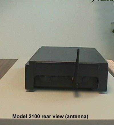
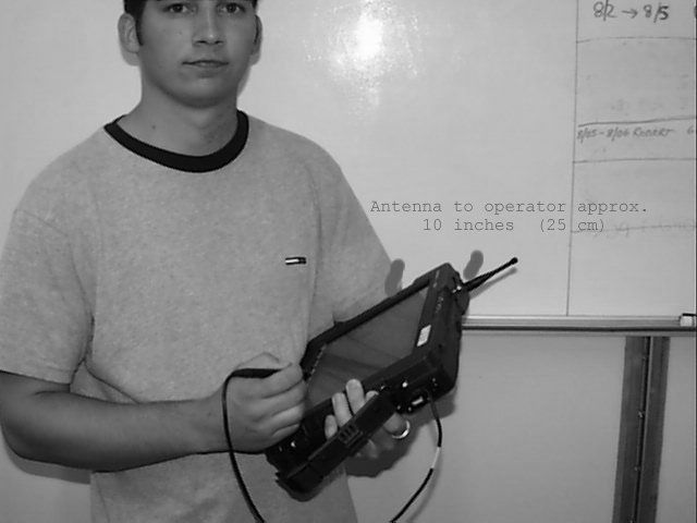
Dear Mr. Chan, Thank you for your prompt review of our application HN2RM182-24. I will try to address your concerns: 1) I have uploaded a new table of host devices and antennas with antenna location and gain information to the RF exposure section of the application. 2) Models 2415 and 6400 have the antenna integrated inside the product, where it is not reachable by the user, while the unit is in operation (the product would have to be taken apart). Model 2100 has the antenna connection in the rear. A new picture demonstrating that has also been uploaded to the RF exposure section. Models 6640 and 6650 both have the antenna connection on top of the unit. A new picture showing their antenna has also been uploaded. 3) We have revised the manual supplements which accompany each product to include following: • A warning to the users of handheld terminals to keep the unit at least 20 cm away from their body when the transceiver is in use. • A warning about some of the antennas being inside the product in some handheld terminals • A warning to the installers to ensure the minimum 20 cm distance between antennas and users, in such a way that the user is not burdened with maintaining that distance. The stationary products are all professional installation products installed by Intermec trained technicians. We will train our installers through these documents and our training procedures to ensure the 20 cm distance in the installation of these products. A copy of the revised user document has been uploaded to the User Documentation section of the application. 4) You made a note indicating that the original Proxim power level was 135 mW. That is puzzling to us as well. Proxim told us this radio is a 100 mW radio, and we only measured 100 mW. I can only guess, that they may have dropped the output power between their original application and now. 5) The grant condition you propose is perfectly acceptable for us. I hope these responses and the uploaded exhibits satisfy your questions. Please feel free to contact us, if you have any further questions. Best regards, Kursat Eroglu, MSEE Sr. EMC Engineer
RF Exposure Info
RM182 Host Device and Antenna List The table below shows the different host devices Model RM182 radio module will be integrated into and the antennas that will be used in conjunction with those hosts. Drawings showing specifications and pictures of the antennas are filed in a separate exhibit. Host Device / Antenna Location FunctionAntennaPart NumberGain (dBi) Patch5909954.5Model 2415 Inside the host Handheld Terminal Patch/Dipole069769 (*)0 Model T2425 On the side of host Handheld Terminal Tuned Dipole0638251.5 Model T2455 On top of display unit Vehicle Mount Terminal Tuned Dipole0661471.0 Model T2485/86 On top of host Stationary Terminal Same as Model T2455 See Model T2455 See Model T2455 Model 5020 At the front end of unit (away from user) Handheld Data Collection Computer Tuned Dipole0666191.5 Model 5055 On top of host Vehicle Mount Data Collection Computer Tuned Dipole805-544 (*)2.0 Model 6400 Inside the host Handheld Data Collection Computer Same as Model 2415 See Model 2415 See Model 2415 Host Device / Antenna Location FunctionAntennaPart NumberGain (dBi) Same as Model T2455 See Model T2455 See Model T2455 Omni065349 (*)9 Omni0633635 Patch0672625 Patch067263 (*)9 Model 2100 At one end of host Access Point Patch0672613 Same antennas as Model 2100 See Model 2100 See Model 2100 Model 2101 At one end of host Access Point Tuned Dipole0697531.5 Model 2102 At one side of host Access PointTuned Dipole0701421.5 Model 6110 On top of the host Handheld Data Collection Computer Same as Model 5055 See Model 5055 See Model 5055 Model 6640 On top of the host PenKey Data Collection Computer Same as Model 5055 See Model 5055 See Model 5055 Model 6650 On top of the host PenKey Data Collection Computer Same as Model 5055 See Model 5055 See Model 5055 (*) marked antennas have been tested for spurious emissions and EIRP, since these are the highest gain representative of each antenna type.
Test Report
EMC MEASUREMENT/TECHNICAL REPORT FOR PART 15.247 APPLICATION MANUFACTURER : Intermec Corp. PRODUCT: MODEL RM182 PCMCIA Radio FCC ID: HN2RM182-24 April 5, 2000 This report concerns : (check one) Original grant___X___ Class II change _______ *Class B verification_______ Class A verification_______ **Class I change_______ Equipment type: 2.4 GHz Spread Spectrum Transceiver Limits used: (check one) CISPR 22 __for digital emissions portion Part 15 __for RF portion Measurement procedure used is ANSI C63.4-1992 unless another is specified. Other test procedure: _______________________________________________________ This report is based on the measurements on Model RM182 . EUT Serial number: 742205-952J0078 . Report reviewed and approved by Kursat Eroglu, EMC Engineer ____________ 6001 36 th Ave. W Everett WA 98203 Phone: 206 356 1765 Fax: 206 348 2633 E-Mail [email protected] Do not bind or staple this report. A horizontal rubber band plus paper clip at top of document is preferred. *Not to be filed with Equipment Authorization Branch of FCC unless requested. Intermec Safety and Compliance Group 2 Table of Contents 1 GENERAL INFORMATION.........................................................................................3 1.1 Summary of Test Results.............................................................................3 1.2 Product Description......................................................................................3 1.3 Antenna System...........................................................................................3 1.4 Class A Justification.....................................................................................3 1.5 RF Exposure................................................................................................3 1.6 Related Submittal(s)/Grant(s).......................................................................3 2 TEST CONDITIONS....................................................................................................4 2.1 Tested System Details.................................................................................4 2.2 Block Diagram of Tested System.................................................................4 2.3 Test Methodology.........................................................................................4 2.4 Test Facility.................................................................................................4 2.5 Test Summary.............................................................................................5 2.6 Environmental Conditions............................................................................5 3 TEST EQUIPMENT.....................................................................................................6 3.1 Test Equipment............................................................................................6 3.2 Accessories..................................................................................................6 4 TEST DATA AND RESULTS.......................................................................................7 4.1 Transmit Range and Channel Utilization Measurement ...............................7 4.2 Peak Power Measurement...........................................................................7 4.3 Channel Bandwidth Measurement................................................................12 4.4 Conducted Out-of-Band Emissions...............................................................12 4.5 Radiated Spurious Emissions.......................................................................18 4.5.1 30 MHz - 1 GHz Band...................................................................18 4.5.2 1 GHz - 24 GHz Band...................................................................18 4.6 Conducted Powerline Emissions...................................................................21 Intermec Safety and Compliance Group 3 1 GENERAL INFORMATION 1.1 Summary of Test Results Model RM182 was tested to the requirements of Part 15 of the FCC Rules for 2.4 GHz band transceivers to verify its continued compliance with Intermec’s antenna set and in a different host. The transceiver module is manufactured by Proxim Inc. As can be seen in section 4 of this report, the product passed all tests with comfortable margins beyond test instrument tolerances. 1.2 Product Description Model RM182 is a 2.4 GHz FHSS transceiver in PCMCIA (PC-Card) form. It is manufactured by Proxim Inc. of Mountain View, CA. It has already been certified by the FCC under FCC ID: IMK-ILC1PC. Intermec Technologies integrates this module into our data automation products such as handheld and vehicle mount barcode terminals, access points, PenKey terminals etc. (A complete list of host devices is given in the attached exhibits). Since some of these products use different antennas than the ones listed by Proxim and as a result of Intermec’s contractual obligations, this report has been prepared to apply for a new grant to Intermec Technologies for the same transceiver. The product is in a standard PCMCIA (PC-Card) enclosure with an MMCX antenna connector. Detailed pictures of the product and the circuit boards are included in the application. Power levels, frequency ranges and channel characteristics are not user adjustable. 1.3 Antenna System and Part 15.203 Compliance For Part 15.203 compliance see separate declarations file included in the application. A complete list of antennas to be used with this product and their drawings are also included in a separate file included in the schematics part of the application. 1.4 Class A Justification (Parts 15.107/109) For Class A justification of Parts 15.107 and 15.109 compliance see separate declarations file included in the application. 1.5 RF Exposure Compliance For compliance with the RF Exposure rules as described in OET Bulletin 65 see separate declarations file included in the application. 1.6 Related Submittal(s)/Gr…
Text truncated - open the document above for the full version.
Test Report
This report file has been split in two pieces in order to accommodate the large file size. For pages 1 through 11, please see the file with description Part 1 of 2. Intermec Safety and Compliance Group 12 4 TEST DATA AND RESULTS (continued) 4.3 Channel Bandwidth Measurement 4.3.1 Procedure The EUT was put into a continuous transmit mode. The analyzer was set to a 2 MHz span around the selected channel with 30 kHz resolution bandwidth and 30 kHz video bandwidth. The analyzer was put into max hold mode and the peak value measured. A threshold line was put 20 dB below the peak. Two markers were set at the intersection of the signal and the 20 dB line. The frequency difference between the markers was recorded as the 20 dB bandwidth. No external attenuator was used. Cable losses were automatically compensated by the analyzer. The same procedure was repeated for three different channels (low, medium and high) to cover the transmit range. 4.3.2 Results The widest 20 dB bandwidth measured was 997 kHz at 2.402 GHz. The other two channels shown on the following plots had bandwidths of 982 kHz (2.440 GHz) and 957 kHz (2.480 GHz). All bandwidths were below the required 1 MHz limit. Note: All conducted measurements were repeated with radio supply voltage modified to 90% and 110% of the nominal 110V. Since the module power is regulated on-board, no differences due to the voltage variation were observed. 4.4 Conducted Out-of-band Emissions 4.4.1 Procedure The EUT was put into continuous transmit mode. The analyzer was set to 300 kHz RBW (1 MHz for ranges 2,3,4) and 300 kHz VBW (1MHz for rangeS 2,3,4). Then four scans were performed in max hold mode with 30 MHz - 1 GHz, 1 GHz - 3 GHz, 3 GHz - 10 GHz and 10 GHz - 24 GHz ranges. Also the 50 MHz region around the fundamental was investigated. Found peaks are listed in the results section. No external attenuator was used. Cable losses were automatically compensated by the analyzer. The measurements were repeated for channels at 2.402, 2.440 and 2.480 GHz Intermec Safety and Compliance Group 13 4 TEST DATA AND RESULTS (continued) 4.4 Conducted Out-of-band Emissions 4.4.2 Results Plots in following pages show the harmonic and spurious out-of-band emissions of the EUT measured at the antenna connector. All found peaks and their margins are listed in the following tables The EUT was found compliant with the requirements for conducted out-of-band emissions. Frequency (GHz) Emission Type Level (dBm) QP/Avg. Level (dBm) Limit (dBm) (*) Margin (dB) Transmit on channel 1 4.804harmonic-55.60-58.34058.34 7.206harmonic-42.13-46.37046.37 9.608harmonic-53.84-56.27056.27 12.010harmonic-62.07-66.31066.31 Transmit on channel 39 4.880harmonic-40.87-45.21045.21 7.320harmonic-49.56-52.86052.86 9.760harmonic-57.42-60.73060.73 12.200harmonic-44.64-48.22048.22 16.640harmonic-48.92-51.32051.32 17.080harmonic-61.15-65.10065.1 19.520harmonic-54.32-58.08058.08 21.960harmonic-63.18-66.92066.92 Transmit on channel 79 4.960harmonic-38.79-44.06044.06 7.440harmonic-57.86-62.24062.24 12.400harmonic-67.45-71.43071.43 14.880harmonic-68.62-72.03072.03 17.360harmonic-60.12-63.78063.78 (*) Limit for harmonics is 20 dB below the lowest fundamental signal (~20 dBm). For all other emission the limit is given in Part 15 paragraph 209. Intermec Safety and Compliance Group 18 4.5 RADIATED SPURIOUS EMISSIONS 4.5.1.1 30 MHz - 1 GHz Band Procedure First with the transmitter turned off, the EUT was powered up and a pre-scan was performed at 3m by rotating the EUT 360° and changing the antenna height between 1 m and 4 m. All suspicious peaks were noted. Then with the quasi-peak detector at 120 kHz RBW all suspicious peaks were scanned in the maximized EUT direction and antenna height. Same measurements were made for both polarizations of the antenna. The analyzer/receiver was programmed to compansate for all loss and gain factors (such as cables, antennas, preamplifiers etc.). The peak and quasi-peak readings were recorded. The limit used was FCC Part 15 class B radiated emissions limit. Then the same measurements were repeated with the transmitter in a constant transmit mode. This time only suspicious peaks in restricted bands (Part 15.205) were investigated. The measurements were performed three times for each type of the antennas (dipole, patch and omnidirectional). 4.5.1.2 30 MHz - 1 GHz Band Results All emissions measured were below the limit. The table on following pages shows the measured values above 20 dB margin, system loss/gain factors for those emissions and the position of the EUT and the measurement antenna. 4.5.2.1 1 GHz - 24 GHz Band Procedure With the transmitter in continuous transmit mode, a pre-scan of the EUT was performed at 1m by rotating the EUT 360° and changing the antenna height between 1m and 4m. All suspicious peaks were noted. Then with the average-peak detector at 1 MHz RBW all suspicious peaks were scanned in the maximized EUT direction and antenna height. Same measurements were made for both polarizations of the antenna. The analyzer/receiver was programmed to compansate for all loss and gain factors (such as cables, antennas, preamplifiers etc.). A 10 dB correction factor was added to the readings for the reduction of measurements distance. The peak and average readings were recorded. The limits used were the limits specified in paragraphs 205 (restricted bands), 209 (spurious emissions), 247 (c) (harmonic emissions) of Part 15. The measurements were performed three times for the highest gain of each type of the antennas (dipole, patch and omnidirectional). 4.5.2.2 1 GHz - 24 GHz Band Results The tables on following pages show the measured values, system loss/gain factors for those emissions and the position of the EUT and the antenna. Since no emissions were found above 12.5 GHz, the band between 18 GHz and 24 GHz was not scanned. Intermec Safety and Compliance Group 19 ReadingAntennaSystemAzimuthAntenna FrequencyPeakQPFactorLossLimitAngleHeightPolariz.Margin (MHz)(dBuV/…
Text truncated - open the document above for the full version.
Contact Information
Applicant
Brian Rudick(VP & GC, Honeywell Scanning & Mobility)
Technical Contact
Intermec Technologies Corp.Kursat Eroglu
[email protected]425 356 1765
6001 36th Ave W · Everett, Washington · United States
Non-Technical Contact
Intermec Technologies Corp.Kursat Eroglu
[email protected]425 356 1765
Technical Specifications
| # | Rule Parts | Frequency Range | Power Output | Tolerance |
|---|---|---|---|---|
| 1 | 15C | 2.40 GHz - 2.48 GHz | 100.00 mW | ppm |
Other Applications from Intermec Technologies Corporation

HN2-BTM311
Nov 23, 2004BTM311
Equipment Class
DTS - Digital Transmission System
HN2-802CF13E
Nov 07, 2004EasyLAN
Equipment Class
DTS - Digital Transmission System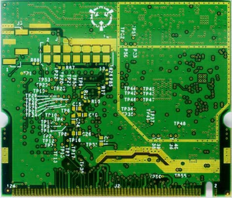
HN2WAMIG2
Nov 18, 2003802MIG2
Equipment Class
DTS - Digital Transmission System
HN2SB555-2
Sep 04, 2003SB555 Radio in 700C
Equipment Class
PCE - PCS Licensed Transmitter held to ear
HN22011B-2
Jul 28, 20032011B Radio in 700C
Equipment Class
DTS - Digital Transmission System