HN2UAPRFID-900
Intermec Technologies Corporation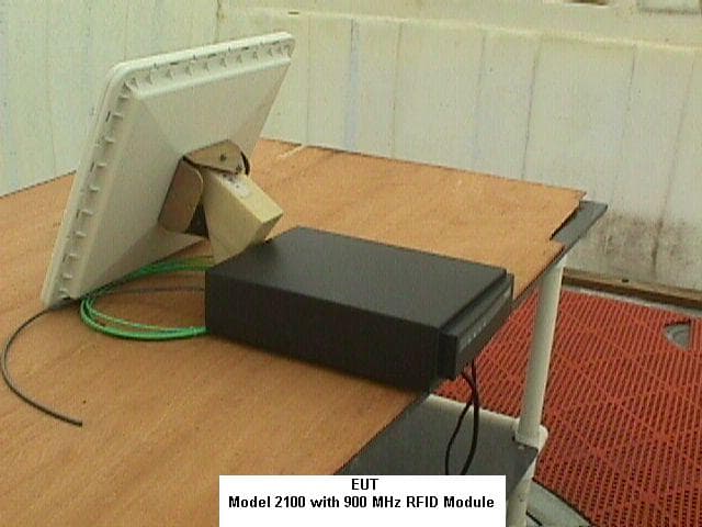
Click to zoom
Application Details
- Equipment Class
- DSS - Part 15 Spread Spectrum Transmitter
- Date of Grant
- Mar 20, 2000
- Application Purpose
- Original Equipment
- Date of Application
- Nov 07, 1999
- Frequency Range
- 902.60000000 - 927.40000000
- Country
- United States
Documents & Files
Document Text
Text extracted from the exhibit documents filed with the FCC. Open a document above to read the original.
Users Manual
P/N 06XXXX-001 Important 2100 Information! (For 900 MHz and 2.4 GHz RFID Modules) Contents For Users in the United States and Canada..............................................................................................................2 2 2100 Manual Supplement For Users in the United States and Canada Place this supplement in your manual. This device complies with Part 15 of the FCC Rules and with RSS-210 of Industry Canada. Operation is subject to the following two conditions: (1) This device may not cause harmful interference, and (2) This device must accept any interference received, including interference that can cause undesired operation. Federal Communications Commission Compliance This equipment is intended for operation in a commercial environment, in compliance with the requirements for a Class A digital device, pursuant to Part 15 of the FCC Rules, and it must not be used in a residential environment; however, it has also been tested and found to comply with the more stringent requirements for a Class B device, pursuant to Part 15 of the FCC Rules. It generates, uses, and can radiate radio frequency energy. If not installed and used in accordance with the instruction manual, it may cause interference to radio communications. If this equipment causes interference, the user will be required to correct the interference at the user’s own expense. Note: In order to maintain compliance with FCC Rules, the input/output (I/O) cables that interconnect between the device and any peripheral must be as specified by Intermec. Warning: FCC regulations limit exposure to radiofrequency (RF) radiation. To comply with these regulations, operators of this device must maintain a distance of at least 7 cm (2.75 inches) from the cover on the antenna assembly (The cover on the antenna is the dome shaped surface). While the device is on, the operator’s body and parts of the body such as eyes, hands, or head, must be 7 cm (2.75 inches) or farther from the cover of the antenna assembly. FCC regulations also require that the antenna assembly of this device be installed in accordance with the installation procedures in this manual to allow the operator to comply with this limit. Caution Changes or modifications not expressly approved by Intermec could void the user’s authority to operate this equipment. 3 2100 Manual Supplement For Users in the United States and Canada (cont.) Industry Canada Compliance This Class B digital apparatus meets all requirements of the Canadian Interference- Causing Equipment Regulations. This device requires a radio license, unless it is used totally inside a building. (The user must obtain this license.) Cet appareil numérique de la classe B respecte toutes les exigences du Règlement sur le matériel brouilleur du Canada. Cet appareil exige une license radio à moins d’être entièrement installé dans un bâtiment. (L’utilisateur doit obtenir cette license.) Safety Agency Approvals This device is UL Listed and CSA Certified. P/N 06XXXX-001
Users Manual
P R O D U C T P R O F I L E Amtech Systems DivisionAmtech Systems Division Features •Fixed reader/programmer board set designed for integration into OEM controller or as option to Intermec 2100 UAP •Provides RFID data collection integrated into local area network when configured as option to Intermec 2100 UAP •Spread-spectrum frequency- hopping RFID reader/ programmer board set coexists with RF data collection network •Wired or wireless connection through 2100 UAP •Rugged industrial environment design •Unlicensed RFID readers and tags using Intellitag 500-series UHF OEM products can be integrated for use in applications that require read ranges up to 7 meters (22.96 ft) Intellitag 500 reader/programmer board sets are offered for integration into radio frequency identification (RFID) solutions requiring read range, multitag sort, read/write, and memory capacity not provided by older, less flexible proximity technology. The fixed reader/programmer board set is designed as an option to the Intermec 2100 Universal Access Point (UAP), but it may be integrated into other microcontroller-based systems. Readers can be programmed for read only or read/write operation. A powerful anticollision algorithm allows up to 50 tags per second to be scanned, regardless of the number of tags in the read zone. Intermec's Amtech Systems Division, with over a decade of success designing, producing, installing, and supporting RFID solutions worldwide, is developing a range of Intellitag 500 RFID inserts, tags, scanners, and programmer subsystems for availability beginning in 1999. These products are available to Intermec systems integration partners in established transportation and security access RFID applications, as well as growing applications in supply chain management, retail operations, manufacturing, logistics, health care and many more. READER PRODUCTS Intellitag 500 Series UHF OEM Reader Products ® S P E C I F I C A T I O N S North America • 6001 36th Avenue West • P.O. Box 4280 • Everett, Washington 98203-9280 • 1 (800) 347-2636 tel • 1 (319) 369-3324 fax • Norand Mobile Systems Division • 550 2nd Street S.E. • Cedar Rapids, Iowa 52401 • 1 (800) 452-2757 tel • 1 (319) 369-3453 fax • Amtech Systems Division • 19111 Dallas Parkway, Suite 300 • Dallas, Texas 75287-3106 • 1 (800) 923-4824 toll-free • 1 (972) 733-6600 tel • 1 (972) 733-6699 fax Europe/Middle East/Africa • Sovereign House • Vastern Road • Reading, Berkshire,RG1 8BT • United Kingdom • +44 118 987 9400 tel • +44 118 987 9401 fax Asia/Pacific/Latin America • 6001 36th Avenue West • P.O. Box 4280 • Everett, Washington 98203-9280 • 1 (800) 347-2636 tel • 1 (319) 369-3324 fax • AmtechSystems Division • 19111 Dallas Parkway, Suite 300 • Dallas, Texas 75287-3106 • 1 (800) 923-4824 toll-free • 1 (214) 360-9436 tel • 1 (972) 733-6699 fax Label Products and Supplies - North America • 1 (513) 874-5882 tel • 1 (513) 874-8487 fax • or 1 (800) 227-9947 tel • 1 (800) 227-1707 fax • Latin America/Asia Pacific • 1 (513) 870-7930 Int’l phone • 1 (513) 874-3613 Int’l fax • Europe/Middle East/Africa +31 24 372 3100 tel • +31 24 378 0070 fax Worldwide Fax Document Retrieval Service • 1 (650) 556-8447 tel • 1 (800) 755-5505 (North America Only) Internet • www.intermec.com E-mail • [email protected] © 1999 Amtech Systems Corporation. (Amtech Systems Corporation is a wholly owned subsidiary of Intermec Technologies Corporation.) All rights reserved. Amtech is a registered trademark of Amtech Systems Corporation. All other trademarks listed are the property of their respective owners. Contents subject to change. Printed in the U.S.A. Where Information Gets Down To Business ™ COMMUNICATIONS Frequency Fixed reader/programmer board set only: 915 MHz unlicensed FCC spread-spectrum frequency-hopping Intermec 2100 UAP with fixed reader/programmer module: 915 MHz unlicensed FCC spread- spectrum frequency-hopping Interfaces Fixed reader/programmer board set: serial interface 2100 UAP: 10BaseT 10Base2 (Optional)900MHz, 2.45 GHz OpenAir™, IEEE 802.11 Direct Sequence, or IEEE 802.11 Frequency Hopping RFLAN SOFTWARE FEATURES Protocols Fixed reader/programmer board set: Intermec ASD interface specification Intermec 2100 UAP with fixed reader/programmer module: available software fully supports the ANS NCITS 256-1999 for item management Data Rate Read 8 bytes of data from tag in less than 12 ms Write a single byte of data to a tag in less than 25 ms Multitag Access User-specified groups within a population of tags can be selected, read from, and/or written to using multitag access commands. POWER REQUIREMENTS Fixed Reader/Programmer Board Set Only 8 VDC 2100 UAP 100-240 VAC auto-ranging ENVIRONMENTAL Operating Temperature 0ºC to +50ºC (+32ºF to +122ºF) Storage Temperature -20ºC to +70ºC (+4ºF to +158ºF) OPTIONS General-Purpose Input/Output Circuits (reader/programmer) Interfaces for input and output circuits to monitor sensors and control other devices READ/WRITE PERFORMANCE Read/write performance varies with RFID inserts, tags, and antenna configurations. Sample dual antenna configuration is illustrated below. Read/Write Ranges Write ranges are approximately 70% of the effective read ranges of the RFID insert and tag. Read Range Examples Ranges are listed for RFID insert and tag using frequency-hopping FCC unlicensed operation reader and dual antennas. 6 Meters (19.68 ft): 915 MHz 16 x 100 x .4 mm (.63 x 3.94 x .016 in) RFID insert 7 Meters (22.96 ft): 915 MHz 33 x 105 x 3 mm (1.30 x 4.13 x .12 in) tag Intellitag 500 Series UHF OEM Reader Products ® 411462-003 8/99
Users Manual
P/N 06XXXX-001 Important 2100 Information! (For 900 MHz and 2.4 GHz RFID Modules) Contents For Users in the United States and Canada....................................................................................2 2 2100 Manual Supplement For Users in the United States and Canada Place this supplement in your manual. This device complies with Part 15 of the FCC Rules and with RSS-210 of Industry Canada. Operation is subject to the following two conditions: (1) This device may not cause harmful interference, and (2) This device must accept any interference received, including interference that can cause undesired operation. Federal Communications Commission Compliance This equipment is intended for operation in a commercial environment, in compliance with the requirements for a Class A digital device, pursuant to Part 15 of the FCC Rules, and it must not be used in a residential environment; however, it has also been tested and found to comply with the more stringent requirements for a Class B device, pursuant to Part 15 of the FCC Rules. It generates, uses, and can radiate radio frequency energy. If not installed and used in accordance with the instruction manual, it may cause interference to radio communications. If this equipment causes interference, the user will be required to correct the interference at the user’s own expense. Note: In order to maintain compliance with FCC Rules, the input/output (I/O) cables that interconnect between the device and any peripheral must be as specified by Intermec. Installation Warning: FCC regulations limit exposure to radiofrequency (RF) radiation. To comply with these regulations, this device must be installed in such a way that the operators of this device will not be closer than 7 cm (2.75 inches) for 2.4 GHz version 12 cm (4.75 inches) for 900 MHz version from the cover on the antenna assembly under normal operation conditions. While the device is operating, the operator’s body and parts of the body such as eyes, hands, or head, must be 7 cm (2.75 inches) for the 2.4 GHz version 12 cm (4.75 inches) for the 900 MHz version or farther from the cover of the antenna assembly. The installer should also protect him/herself from RF exposure by not operating the device while they are closer than the distance mentioned above. FCC regulations also require that the antenna assembly of this device be installed in accordance with the installation procedures in this manual to allow the operator to comply with this limit. Operator Warning: FCC regulations limit exposure to radiofrequency (RF) radiation. To comply with these regulations, the operators of this device must maintain adistance of at least 7 cm (2.75 inches) for 2.4 GHz version 12 cm (4.75 inches) for 900 MHz version from the cover on the antenna assembly under normal operation conditions. While the device is on, the operator’s body and parts of the body such as eyes, hands, or head, must be 7 cm (2.75 inches) for the 2.4 GHz version 12 cm (4.75 inches) for the 900 MHz version or farther from the cover of the antenna assembly. 3 2100 Manual Supplement For Users in the United States and Canada (cont.) Industry Canada Compliance This Class B digital apparatus meets all requirements of the Canadian Interference- Causing Equipment Regulations. This device requires a radio license, unless it is used totally inside a building. (The user must obtain this license.) Cet appareil numérique de la classe B respecte toutes les exigences du Règlement sur le matériel brouilleur du Canada. Cet appareil exige une license radio à moins d’être entièrement installé dans un bâtiment. (L’utilisateur doit obtenir cette license.) Safety Agency Approvals This device is UL Listed and CSA Certified. Caution Changes or modifications not expressly approved by Intermec could void the user’s authority to operate this equipment. P/N 06XXXX-001
Users Manual
P/N 06XXXX-001 Important 2100 Information! (For 900 MHz and 2.4 GHz RFID Modules) Contents For Users in the United States and Canada....................................................................................2 2 2100 Manual Supplement For Users in the United States and Canada Place this supplement in your manual. This device complies with Part 15 of the FCC Rules and with RSS-210 of Industry Canada. Operation is subject to the following two conditions: (1) This device may not cause harmful interference, and (2) This device must accept any interference received, including interference that can cause undesired operation. Federal Communications Commission Compliance This equipment is intended for operation in a commercial environment, in compliance with the requirements for a Class A digital device, pursuant to Part 15 of the FCC Rules, and it must not be used in a residential environment; however, it has also been tested and found to comply with the more stringent requirements for a Class B device, pursuant to Part 15 of the FCC Rules. It generates, uses, and can radiate radio frequency energy. If not installed and used in accordance with the instruction manual, it may cause interference to radio communications. If this equipment causes interference, the user will be required to correct the interference at the user’s own expense. Note: In order to maintain compliance with FCC Rules, the input/output (I/O) cables that interconnect between the device and any peripheral must be as specified by Intermec. Installation Warning: FCC regulations limit exposure to radiofrequency (RF) radiation. To comply with these regulations, this device must be installed in such a way that the operators of this device will not be closer than 20 cm (8 inches) from the cover on the antenna assembly under normal operation conditions. While the device is operating, the operator’s body and parts of the body such as eyes, hands, or head, must be 20 cm (8 inches) or farther from the cover of the antenna assembly. The installer should also protect him/herself from RF exposure by not operating the device while they are closer than the distance mentioned above. FCC regulations also require that the antenna assembly of this device be installed in accordance with the installation procedures in this manual to allow the operator to comply with this limit. Operator Warning: FCC regulations limit exposure to radiofrequency (RF) radiation. To comply with these regulations, the operators of this device must maintain adistance of at least 20 cm (8 inches) from the cover on the antenna assembly under normal operation conditions. While the device is on, the operator’s body and parts of the body such as eyes, hands, or head, must be 20 cm (8 inches) or farther from the cover of the antenna assembly. 3 2100 Manual Supplement For Users in the United States and Canada (cont.) Industry Canada Compliance This Class B digital apparatus meets all requirements of the Canadian Interference- Causing Equipment Regulations. This device requires a radio license, unless it is used totally inside a building. (The user must obtain this license.) Cet appareil numérique de la classe B respecte toutes les exigences du Règlement sur le matériel brouilleur du Canada. Cet appareil exige une license radio à moins d’être entièrement installé dans un bâtiment. (L’utilisateur doit obtenir cette license.) Safety Agency Approvals This device is UL Listed and CSA Certified. Caution Changes or modifications not expressly approved by Intermec could void the user’s authority to operate this equipment. P/N 06XXXX-001
ID Label/Location Info
Prototype Label on Model 2100 with 900 MHz RFID Module: Model 2100 with 900 MHz RFID Module Regulatory Label (Prototype) Model 2100 (RFID)FCC ID: HN2UAPRFID-900 Configuration: 2100C61XXXB91Canada: 1223 XXXXXX RSS/CNR 210 ICES-003 This device complies with Part 15 of the FCC Rules and with RSS-210 of Industry Canada. Operation is subject to the following two conditions: (1) This device may not cause harmful interference, and (2) This device must accept any interference received, including interference that can cause undesired operation. See Manual.Referézvous àla documentation. Prototype Label on Model 2100 with 900 MHz RFID Module (close-up view):
RF Exposure Info
Dear Mr. Chan, Since Mr. Dichoso requested the response to the information request about RF exposure issues to be kept in the RF Exposure Info folder, I am generating this pdf file and uploading it as exhibit instead of responding via the email. 1) We agree with your assessment in item one. Our compliance should be through the calculations and measures we took as explained below. 2) As the test report shows, the maximum output power was 297 mW. The nominal antenna gain is 6 dBi at the maximum point (90 degrees to the antenna surface). Using the formula P D = P T * G T / 4πd 2 and the MPE limit of f/1500 with f=900 we arrive at the safe distance of 12 cm for uncontrolled environments. Considering this is the peak power density and the average power density will be much lower during normal operation conditions and it is also valid for only the peak direction of the antenna gain, the harmlessness of our product becomes obvious. Therefore, we believe the 12 cm distance warning to the installers and users should provide more than adequate protection. As you can see in the pictures and drawings submitted, the product is not a mobile product. It is designed to be used in fixed locations with the antenna(s) mounted on walls or similar fixed locations. As you can see in the new uploaded Manual Supplement which is included with each unit for installers and operators, the warnings have been clearly stated. 3) The product will always be installed by trained Intermec personnel or trained resellers and never by the users. Therefore it is considered a “professional installation” category product. Again as you can see in the revised Manual Supplement installers as well as operators are warned about the effects of RF exposure, despite the relatively low power density. I hope, the answers above satisfy your requirements. Please feel free to contact us, if you have any further questions. Sincerely, Kursat Eroglu, MSEE Sr. EMC Engineer Intermec Technologies Corp.
RF Exposure Info
March 20, 2000 Dear Mr. Chen, Since Mr. Dichoso requested I place our response into the RF Expo folder, I am also including this letter. I would like to apologize for the misunderstanding in our recent response. Due to a misinterpretation on our part, we placed the wrong distances in our Manuals. I have corrected those and revised the warnings for installers and users with the 20 cm warning. As I explained before, this product is intended for industrial controlled environment installations. It will only be installed by trained Intermec personnel. Our training guidelines include RF safety issues such as keeping the installers and users away from the antenna. Please let me know, if you have any further questions regarding this product. Sincerely, Kursat Eroglu, MSEE Sr. EMC Engineer
Schematics
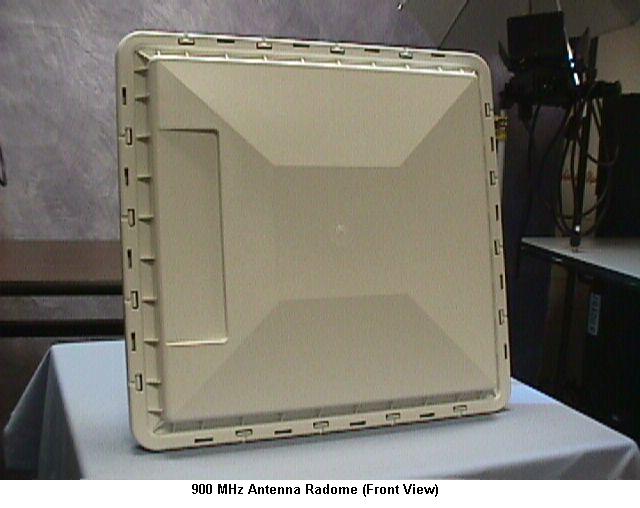
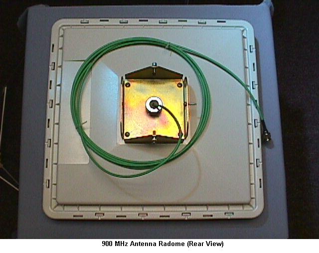
915 MHz Antenna Enclosure, Amtech Systems Division, Intermec Technologies Two pieces snap together to form complete enclosure.
Test Report
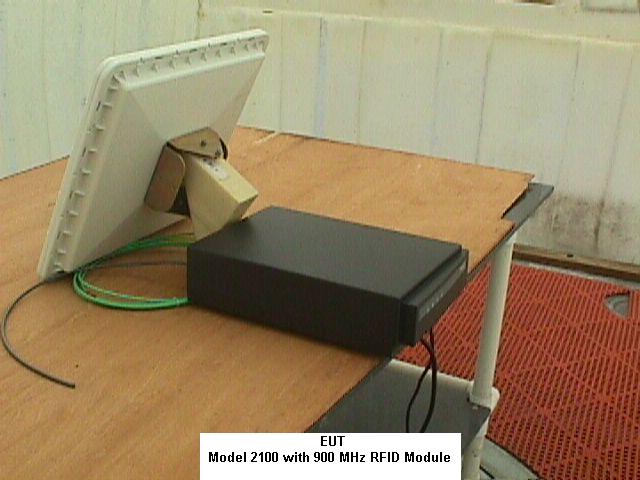
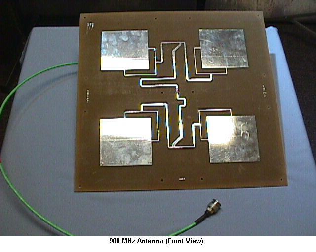
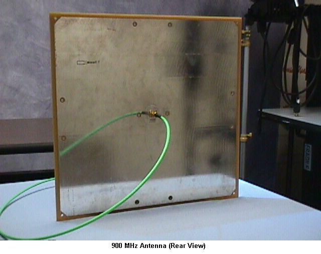
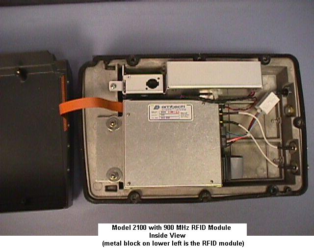
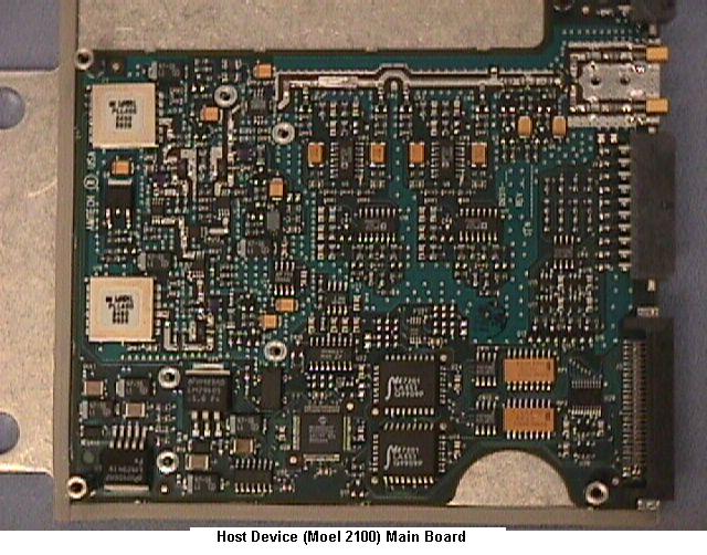
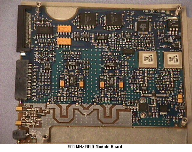
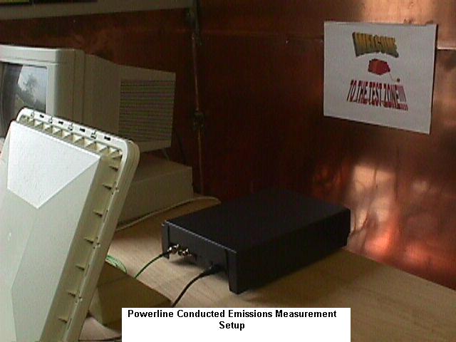
EMC MEASUREMENT/TECHNICAL REPORT FOR PART 15.247 APPLICATION MANUFACTURER : Intermec Corp. PRODUCT: MODEL 2100 with 900 MHz RFID Module Configuration: 2100C61XXXB91 FCC ID: HN2UAPRFID-900 October 15, 1999 This report concerns : (check one) Original grant___X___ Class II change _______ *Class B verification_____X__ Class A verification_______ **Class I change_______ Equipment type: 900MHz Spread Spectrum Transceiver Limits used: (check one) CISPR 22 __for digital emissions portion Part 15 __for RF portion Measurement procedure used is ANSI C63.4-1992 unless another is specified. Other test procedure: _______________________________________________________ This report is based on the measurements on Model 2100 . EUT Serial number: 915T0018 . Report reviewed and approved by Kursat Eroglu, EMC Engineer ____________ 6001 36 th Ave. W Everett WA 98203 Phone: 206 356 1765 Fax: 206 348 2633 E-Mail [email protected] Do not bind or staple this report. A horizontal rubber band plus paper clip at top of document is preferred. *Not to be filed with Equipment Authorization Branch of FCC unless requested. Intermec Safety and Compliance Group 2 Table of Contents 1 GENERAL INFORMATION.........................................................................................3 1.1 Summary of Test Results.............................................................................3 1.2 Product Description......................................................................................3 1.3 Antenna System...........................................................................................3 1.4 Class A Justification.....................................................................................3 1.5 Related Submittal(s)/Grant(s)........................................................................3 2 TEST CONDITIONS....................................................................................................4 2.1 Tested System Details.................................................................................4 2.2 Block Diagram of Tested System.................................................................4 2.3 Test Methodology........................................................................................4 2.4 Test Facility.................................................................................................4 2.5 Test Summary.............................................................................................5 2.6 Environmental Conditions............................................................................5 3 PRODUCT LABELING................................................................................................5 3.1 Location of Label on EUT.............................................................................5 4 TEST EQUIPMENT.....................................................................................................6 4.1 Test Equipment............................................................................................6 4.2 Accessories..................................................................................................6 5 TEST DATA AND RESULTS.......................................................................................7 5.1 Band Usage and Dwell Time........................................................................7 5.2 Peak Power Measurement...........................................................................7 5.3 Channel Bandwidth Measurement................................................................12 5.4 Conducted Out-of-Band Emissions..............................................................12 5.5 Radiated Emissions......................................................................................18 5.6 Conducted Powerline Emissions...................................................................19 Intermec Safety and Compliance Group 3 1 GENERAL INFORMATION 1.1 Summary of Test Results Model 2100 with 900 MHz RFID module was tested to the requirements of Part 15.247 of the FCC Rules for 900 MHz band spread spectrum transceivers to verify its compliance. The product passed all tests with comfortable margins beyond test instrument tolerances. 1.2 Product Description Model 2100 with 900 MHz RFID module is an RFID configuration of our Model 2100 Universal Access Point, which contains a 900 MHz RFID reader module. The module uses 900 MHz spread spectrum signals to interrogate, and program RFID tags. The module has a sheet metal enclosure inside the v-cast metal enclosure of Model 2100. It uses two 6 dB patch antennas alternatively. Detailed pictures of the product and the circuit boards are in the attaced exhibits. Power levels, frequency ranges and channel characteristics are not user adjustable. 1.3 Antenna System Model 2100 with 900 MHz RFID module uses two 6 dB patch antennas alternatively for spacial and polarization diversity. The antennas are connected through a TNC connector to the transmitter. Compliance with part 15.203 is achieved by an integrated RFID tag on the antenna, which identifies the antenna and is hardwired to the transmission cable. When the product is turned on it transmits an interrogation signal to the antenna. If it cannot identify the antenna through the transmission cable, it will not operate. Since the identification is made through the transmission cable only, no other antennas can be used with the product. 1.4 Class A Justification Intermec serves industrial customers such as warehouses, factories, storage facilities etc. Since this ruggedized product is used in these environments it falls under Part 15 Class A for digital emissions. 1.5 Related Submittal(s)/Grant(s) A similar version of this transceiver using 2.4 GHz was certified by the FCC to IBM in 1997 under the FCC identifier ANORFID-2000. The same 2.4 GHz module is now in process of being certified in our Model 2100 under FCC ID: HN2UAPRFID-24. Intermec Safety and Compliance G…
Text truncated - open the document above for the full version.
Test Report
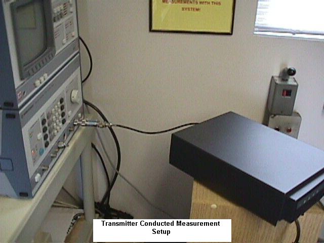
Intermec Safety and Compliance Group 8 Intermec Safety and Compliance Group 9 Intermec Safety and Compliance Group 10 Intermec Safety and Compliance Group 11 Intermec Safety and Compliance Group 12 5 TEST DATA AND RESULTS (continued) 5.3 Channel Bandwidth Measurement 5.3.1 Procedure The EUT was put into a continuous transmit mode. The analyzer was set to a 1 MHz span around the selected channel with 100 kHz resolution bandwidth and 100 kHz video bandwidth. The analyzer was put into max hold mode and the peak value measured. A threshold line was put 20 dB below the peak. Two markers were set at the intersection of the signal and the 20 dB line. The frequency difference between the markers was recorded as the 20 dB bandwidth. A 6 dB external attenuator was used and compansated in the measurement. Cable losses were automatically compensated by the analyzer. The same procedure was repeated for three different channels (low, medium and high) to cover the transmit range. 5.3.2 Results The widest 20 dB bandwidth measured was 329 kHz BW at 927.4 MHz. The other two were 324 kHz at 914.6 MHz and 323 kHz at 902.6 MHz. All bandwidths were below the required limit of 1 MHz. 5.4 Conducted Out-of-band Emissions 5.4.1 Procedure The EUT was put into continuous transmit mode. The analyzer was set to 1 MHz RBW and 1 MHz VBW. Then three scans were performed in max hold mode with 30 MHz - 1 GHz, 1 GHz – 2.5 GHz, 2.5 GHz - 10 GHz ranges. Also the 50 MHz region around the fundamental was investigated. Found peaks are listed in the results section. A 6 dB external attenuator was used and compansated in the measurements. Cable losses were automatically compensated by the analyzer. The measurements were repeated for channels at 902.6 MHz, 914.6 MHz and 927.4 MHz. 5.4.2 Results Plots in following pages show the harmonic and spurious out-of-band emissions of the EUT measured at the antenna connector. All found peaks and their margins are listed in the following tables The EUT was found compliant with the requirements for conducted out-of-band emissions. For file size considerations, this report has been split into 4 pieces. Please see the next file for the rest of the report.
Test Report
Intermec Safety and Compliance Group 13 Intermec Safety and Compliance Group 14 Intermec Safety and Compliance Group 15 Intermec Safety and Compliance Group 16 Intermec Safety and Compliance Group 17 5.4 Conducted Out-of-band Emissions (cont.) 5.4.1 Results (cont.) Frequency (GHz) Emission Type Level (dBm) Avg. Level (dBm) Limit (dBm) (*) Margin (dB) Transmit on low channel 1.8052Harmonic-38.5-42.6547.6 2.7078Harmonic-32.1-35.3540.3 3.6104Harmonic-33.4-35.1540.1 4.5130Harmonic-39.8-41.0546 5.4156Harmonic-42.5-44.7549.7 Transmit on medium channel 1.8292Harmonic-32.8-34.3539.3 2.7438Harmonic-30.8-32.5537.5 3.6584Harmonic-39.4-42.1547.1 4.5730Harmonic-33.5-36.2541.2 Transmit on high channel 1.8548Harmonic-32.2-34.6539.6 2.7822Harmonic-29.7-31.4536.4 3.7096Harmonic-38.6-41.1546.1 4.6378Harmonic-37.2-39.4544.4 (*) Limit for harmonics is 20 dB below the lowest fundamental signal. For all other emission the limit is given in Part 15 paragraph 209. For file size considerations, this report has been split into 4 pieces. Please see the next file for the rest of the report.
Test Report
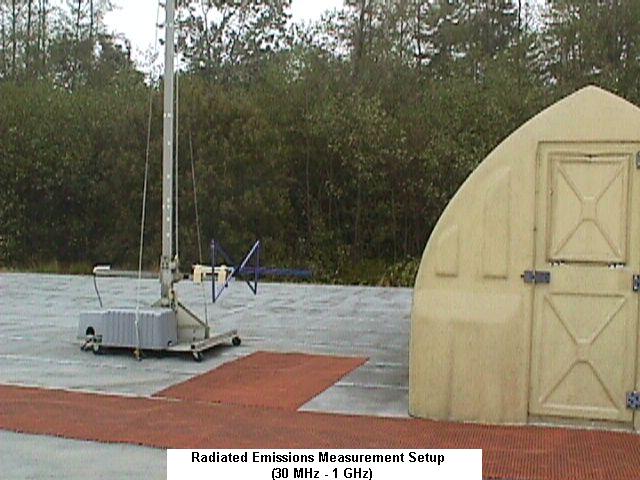
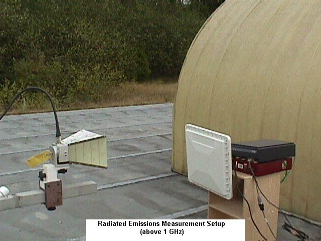
Intermec Safety and Compliance Group 18 5.5 RADIATED SPURIOUS EMISSIONS 5.5.1.1 30 MHz - 1 GHz Band Procedure With the EUT first in transmit mode, then in receive mode a prescan of the emissions in the 30 MHz – 1 GHz range was performed. Then suspicious peaks were closely measured while the antenna, table azimuth and EUT cabling were maximized for worst case emissions. The analyzer/receiver was programmed to compansate for all loss and gain factors (such as cables, antennas, preamplifiers etc.). The peak and quasi-peak readings were recorded. The limit used was FCC Part 15 class B radiated emissions limit. 5.5.1.2 30 MHz - 1 GHz Band Results All emissions measured were below the limit. The following table shows the measured values, system loss/gain factors for those emissions and the position of the EUT and the measurement antenna. 5.5.2.1 1 GHz - 10 GHz Band Procedure With the transmitter in continuous transmit mode, a pre-scan of the EUT was performed at 1m by rotating the EUT 360° and changing the antenna height between 1m and 4m. All suspicious peaks were noted. Then with the average-peak…
Text truncated - open the document above for the full version.
Contact Information
Applicant
Brian Rudick(VP & GC, Honeywell Scanning & Mobility)
Technical Contact
Intermec Technologies CorporationKursat Eroglu
[email protected]425 356 1765
6001 36th Ave W · Everett, Washington · United States
Non-Technical Contact
Intermec Technologies CorporationKursat Eroglu
[email protected]425 356 1765
Technical Specifications
| # | Rule Parts | Frequency Range | Power Output | Tolerance |
|---|---|---|---|---|
| 1 | 15C | 902.6 MHz - 927.4 MHz | 300.00 mW | ppm |
Other Applications from Intermec Technologies Corporation

HN2-BTM311
Nov 23, 2004BTM311
Equipment Class
DTS - Digital Transmission System
HN2-802CF13E
Nov 07, 2004EasyLAN
Equipment Class
DTS - Digital Transmission System
HN2WAMIG2
Nov 18, 2003802MIG2
Equipment Class
DTS - Digital Transmission System
HN2SB555-2
Sep 04, 2003SB555 Radio in 700C
Equipment Class
PCE - PCS Licensed Transmitter held to ear
HN22011B-2
Jul 28, 20032011B Radio in 700C
Equipment Class
DTS - Digital Transmission System