HN2WN-5MP01WN-5MP01
Intermec Technologies Corporation
Click to zoom
Application Details
- Equipment Class
- NII - Unlicensed National Information Infrastructure TX
- Date of Grant
- Oct 21, 2002
- Application Purpose
- Original Equipment
- Date of Application
- Oct 21, 2002
- Equipment Note
- WN-5MP01
- Frequency Range
- 5260.00000000 - 5320.00000000
- Country
- United States
Documents & Files
Document Text
Text extracted from the exhibit documents filed with the FCC. Open a document above to read the original.
Users Manual
Exhibit J: User Manual FCC ID: HN2WN-5MP01 Part No. 072869-001 Important WN-5MP01 Information! Place this supplement in your manual. For Users in the United States and Canada This device complies with Part 15 of the FCC Rules and with RSS-210 of Industry Canada. Operation is subject to the following two conditions: (1) This device may not cause harmful interference, and (2) This device must accept any interference received, including interference that can cause undesired operation. Federal Communications Commission Compliance This equipment is intended for operation in a commercial environment, in compliance with the requirements for a Class A digital device, pursuant to Part 15 of the FCC Rules, and it must not be used in a residential environment. It generates, uses, and can radiate radio frequency energy. If not installed and used in accordance with the instruction manual, it may cause interference to radio communications. If this equipment causes interference, the user will be required to correct the interference at the user’s own expense. Operation Warning To comply with the FCC’s RF exposure requirements and minimize health hazards: The user shall stay at least 20 cm (8 in) away from the antenna of this device, when the device is in use. The operation of this device is restricted to indoors only for the 5.150- 5.350 GHz configuration with integral antenna. No such restriction is placed on the 5.250-5.350 GHz configuration with removable antennas. This device will automatically discontinue transmission in case of either absence of information to transmit or operational failure. Installation Warning To comply with the FCC’s RF exposure requirements and minimize health hazards: Access points must be installed in such a way that the user will be at least 20 cm (8 in) away from the antenna, when the device is in use. The installers should not forget that the burden of maintaining this distance is on the installer and not the user. The antennas should be installed in a manner that will comply with this requirement. Changes or modifications not expressly approved by Intermec could void the user’s authority to operate this equipment. To maintain compliance with FCC Rules, the input/output (I/O) cables that interconnect between the device and any peripheral must be as specified by Intermec. Industry Canada Compliance This Class A digital apparatus meets all requirements of the Canadian Interference-Causing Equipment Regulations. This device requires a radio license, unless it is used totally inside a building. (The user must obtain this license.) Cet appareil numérique de la classe A respecte toutes les exigences du Règlement sur le matériel brouilleur du Canada. Cet appareil exige une license radio à moins d’être entièrement installé dans un bâtiment. (L’utilisateur doit obtenir cette license.) Agency Approvals This device is UL and cUL listed (UL 1950/C22.2 #950) for safety when powered by an Intermec power supply. Part No. 072869-001 *072869-001* *072869-001* 6001 36th Avenue West Everett, WA 98203 U.S.A. www.intermec.com © 2002 Intermec Technologies Corp. All Rights Reserved
Users Manual
Exhibit J: User Manual FCC ID: HN2WN-5MP01 Part No. 072831-001 1 Important WA21/WA22 Information! Contents For Users in the United States and Canada.......................................................................... 2 For Users Outside of the United States and Canada ............................................................ 3 Pour les utilisateurs en dehors du Canada et des Etat-unis ................................................... 3 Für Benutzer außerhalb von Kanada und den Vereinigten Staaten ....................................... 4 Per gli utenti al di fuori del Canada o degli Stati Uniti ........................................................ 4 Para Usuarios Fuera de Canada o de los Estados Unidos...................................................... 5 Para Usuários fora do Canadá ou dos Estados Unidos ......................................................... 5 .............................................................................................. 6 2 For Users in the United States and Canada Place this supplement in your manual. Federal Communications Commission Compliance This device complies with Part 15 of the FCC Rules. Operation is subject to the following two conditions: (1) This device may not cause harmful interference, and (2) This device must accept any interference received, including interference that can cause undesired operation. This equipment is intended for operation in a commercial environment, in compliance with the requirements for a Class A digital device, pursuant to Part 15 of the FCC Rules, and it must not be used in a residential environment; however, it has also been tested and found to comply with the more stringent requirements for a Class B device, pursuant to Part 15 of the FCC Rules. It generates, uses, and can radiate radio frequency energy. If not installed and used in accordance with the instruction manual, it may cause interference to radio communications. If this equipment causes interference, the user will be required to correct the interference at the user’s own expense. Caution Conseil Changes or modifications not expressly approved by Intermec could void the user’s authority to operate this equipment. Caution Conseil Regulatory statements relating to the transceivers contained in this product are in a separate manual supplement accompanying the transceiver. Note In order to maintain compliance with FCC Rules, the input/output (I/O) cables that interconnect between the device and any peripheral must be as specified by Intermec. Industry Canada Compliance This Class B digital apparatus meets all requirements of the Canadian Interference-Causing Equipment Regulations. Cet appareil numérique de la classe B respecte toutes les exigences du Réglement sur le matériel brouilleur du Canada. Additional EMI/RFI Compliance This device meets the Class B limit requirements of CISPR 22. Safety Agency Approvals This device is UL and cUL Listed (UL 1950/C22.2 #950) and TÜV GS Licensed (EN 60950) for safety. 3 For Users Outside of the United States and Canada Place this supplement in your manual. This product complies with EN55022, EN55024, and EN 60950 as required by the EMC Directive 89/336/EEC as amended by 92/31/EEC and by the Low Voltage Directive 73/23/EEC as amended by 93/68/EEC. Safety Agency Approvals This device is UL and cUL Listed (UL 1950/C22.2 #950) and TÜV GS Licensed (EN 60950) for safety. Additional EMI/RFI Compliance This device meets the Class B limit requirements of CISPR 22. This device complies with AS/NZS 3548 and other applicable rules under the Australian EMC framework. Pour les utilisateurs en dehors du Canada et des Etat-unis Veuillez placer ce supplément dans votre manuel. Déclaration de conformité européenne Ce produit est conformé aux normes EN55022, EN55024 et EN 60950 tel qu’exigé par la directive de l’EMC nº 89/336/CEE amendée par l’article 92/31/CEE et par la directive sur la basse tension nº 73/23/CEE amendée par l’article 93/68/CEE. Approbations d'agences pour la sécurité Cet appareil fait partie de la liste UL et cUL (UL 1950/C22.2 n° 950) et il est sous licence TÜV GS (EN 60950) en termes de sécurité. Conformité additionelle à la norme EMI/RFI Cet appareil respecte les limites imposées pour la Classe B par le CISPR 22. 4 Für Benutzer außerhalb von Kanada und den Vereinigten Staaten Legen Sie diese Ergänzung in Ihr Handbuch. Europäische Übereinstimmungserklärung Dieses Produkt entspricht EN55022, EN55024, und EN 60950 in Übereinstimmung mit der EMC-Richtlinie 89/336/EWG, abgeändert durch 92/31/EWG, und der Richtlinie für Niederspannung 73/23/EWG, abgeändert durch 93/68/EWG. Sicherheitszulassungen durch Prüfstellen Dieses Gerät ist in die UL- und die c-UL-Liste (UL 1950/C22.2 Nr. 950) aufgenommen und vom TÜV GS (EN 60950) gemäß der Sicherheitsnorm lizenziert. Zusätzliche Elektromagnetische Störung-Übereinstimmung Dieses Gerät stimmt mit den Grenzbestimmungen der Klasse B von CISPR 22 überein. Per gli utenti al di fuori del Canada o degli Stati Uniti Si prega di collocare questo supplemento nel manuale. Dichiarazione europea di conformità Questo prodotto è conforme a EN55022, EN55024, e EN 60950 come richiesto dalla Direttiva EMC 89/336 CEE, modificata dalla 92/31/CEE e dalla Direttiva sulla bassa tensione 73/23/CEE, modificata dalla 93/68/CEE. Approvazioni relative alla sicurezza Questo prodotto è conforme agli standard di sicurezza UL e cUL (UL 1950/CC22.2 n.950) e TÜV GS (EN 60950). Ulteriore conformità con EMI/RFI Questo dispositivo è conforme ai limiti stabiliti in CISPR 22 per la Classe B. 5 Para Usuarios Fuera de Canada o de los Estados Unidos Por favor, coloque este suplemento dentro de su manual. Declaración de conformidad europea Este producto cumple con las normas EN55022, EN55024, y EN 60950 de acuerdo a lo establecido por la directiva de EMC 89/336/CEE corregida por 92/31/CEE y por la directiva referente al bajo voltaje 73/23/CEE corregida por 93/68/CEE. Aprobación de organismos de seguridad …
Text truncated - open the document above for the full version.
Cover Letter(s)
Exhibit K: Request for Confidentiality FCC ID: HN2WN-5MP01
External Photos
Exhibit D: External Photos FCC ID: HN2WN-5MP01
ID Label/Location Info
Exhibit A: FCC ID Label and Location FCC ID: HN2WN-5MP01 WN-5MP01 and MPCI3A-20 Regulatory Labels WN-5MP01 and MPCI3A-20 Regulatory Labels (close-up)
ID Label/Location Info
Labeling scheme for two FCC ID HN2WN-5MP01 Labeling scheme for two FCC ID HN2MPCI3A-20 Labeling scheme for one FCC ID HN2MPCI3A-20 Labeling scheme for one FCC ID HN2WN-5MP01 Labeling scheme for one FCC ID HN2WN-5MP01 and one FCC ID HN2MPCI3A-20
Internal Photos
Exhibit E: Internal Photos FCC ID: HN2WN-5MP01
Operational Description
Exhibit I: Operational Description FCC ID: HN2WN-5MP01 TDK IEEE802.11a Mini-PCI radio Functional description See: Reference to Block diagram attached. TDK’s IEEE802.11a wireless LAN Mini-PCI radio is a 5.15-5.35Ghz ISM band radio design using OFDM ( O Orthogonal F Frequency D Division M Multiplexing) modulation scheme based on Atheros’s AR5000 chipset. There are three main components in this radio design. 1) RF Front End section: This section includes the receive and transmit signal path for the 5Ghz RF signal, balun impedance transformers, LNA, PA, RX/TX switch, band-pass filter (BPF) and diversity antenna switch. 2) Analog section: This section includes an Atheros’s AR5110 chip, which is an integrated, IEEE802.11a compliant, 5Ghz CMOS transceiver. This section includes a PLL loop filter to set the bandwidth of the on-chip PLL, a 32Mhz crystal, channel select filter, and base band filters for ADC and DAC blocks. 3) Digital section: This section contains an Atheros’s AR5210 chip, which is an IEEE802.11a MAC, Base band processor, and CardBus/PCI Bus interface. This section also includes a serial EEPROM, GPIOs, LEDs, and control signals for the analog and RF section. Transmit operation: In the transmit path, wireless LAN transmitting data is passed between AR5200 and the host system using PCI/CardBus interface. The transfer of data take place through a direct memory access (DMA) mechanism to free the host CPU from performing actual transfer of data. Next, the MAC block within the AR5210, after performing the WEP and CRC operation, deposits the packets received from DMA engine into the 4kB FIFO. The base band processor transfers TX data from MAC, and builds the frame for the analog section AR5110 for transmission. This framed data is digital-to-analog converted by 9-bit current mode DAC and passed to the AR5110 through base band filters. The AR5110 amplifies this analog signal, up converts it to the 5Ghz range, and transmits the signal through an on-chip power amplifier. The signal is impedance matched to 50 ohms with balun transformer, and converts the balanced differential signal to an unbalanced, single- ended signal for transmission. An off-chip power booster further amplifiers this 5Ghz RF signal. After going through an RX/TX switch for TX path, BPF and Diversity antenna switch, RF signal is sent to selected antenna port for transmission. Receive operation: In the receive path, 5Ghz RF signal is received through one of the diversity antenna port and after going the Diversity antenna switch and BPF. RF signal is routed to low noise amplifier for receiving through RX/TX switch. The LNA amplifies the 5Ghz RF signal and sends it to an on-chip 5Ghz LNA within the AR5110 through an impedance matched balun transformer that converts the unbalanced, singled-ended signal to the balanced, differential signal. The received signal is down converted to base band by RF and IF mixer stages within the AR5110 chip, and sent to an amplifier stage through an off-chip channel select filter. The channel select filter ensures that out-of-band signals are suppressed before the signal reaches the programmable gain amplifiers (PGAs). After amplification by PGAs, the received signal is sent to an analog-to-digital converter port of the AR5210 through an anti-aliasing filter. Digital data from the ADC is sent to the base band processor, and is converted to frames and decoded by performing various signal-processing operation. The decoded frames are then passed to the MAC, and subsequently to the host systems through the PCI/CardBus interface. Intermec Technologies Corporation 6001 36 th Avenue West Everett, WA 98203-9280 425.356.1765 tel 425.348.2633 fax www.intermec.com August 29, 2002 To Whom It May Concern: Intermec Technologies, Corp. hereby declares that our Model WN-5MP01 5 GHz UNII transceiver complies with FCC Part 15.407(c) requirements as described below: By design, the radio device will stop transmitting unless continuously presented data from the processor. The discontinuing of transmission in the absence of information occurs by the design of the 802.11 MAC and 802.11a PHY. The discontinuing of transmission in the presence of operational failure occurs when the processor detects an exception interrupt. The interrupt code will cause the AP to reboot to recover from the operational failure. If the interrupt code is also corrupted, a double exception occurs which halts the processor. Our user documentation states this fact and warns the users. If you have any questions, regarding this or any other Intermec products, please feel free to contact me (phone: 425 356 1765, fax: 425 348 2633, email: [email protected]). Sincerely, Carl K. Turk, MSEE Sr. EMC Engineer Intermec Technologies Corp.
Operational Description
MobileLAN WA21 Radio Replacement Instructions 1 About the Radio Upgrade Kit In the MobileLAN access WA21, you may need to add a second radio, replace a malfunctioning radio, or remove one type of radio and replace it with another type of radio. These instructions explain how to add or replace a radio, how to reconfigure the configuration matrix string, and how and where to apply the new labels. At the end of these instructions you can find some troubleshooting information. Note: The country code is programmed into the radio at the factory. The country code should always remain the same in an access point. You should not upgrade an access point with a radio with a different country code. There are three radio upgrade kits that you can order: 802.11b Radio (P/N RWA21A704) 802.11a Full-Range Radio (P/N RWA21A904) 802.11a Mid-Range Radio (P/N RWA21A954) • Mini-PCI radio card • Mini-PCI radio card • Mini-PCI radio card • Retainer clip • Retainer clip • Retainer clip • RF certification label • RF certification label • RF certification label • Radio upgrade kit label • Radio upgrade kit label • Radio upgrade kit label • Antenna cable assemblies (2) • Antenna cable assemblies (2) • Antenna cable assemblies (2) • Antennas (2) To maintain the IP54 rating, Intermec recommends that you also replace this part: • Gasket (P/N 065194-002) You need these tools: • Torx T20 (to open the access point) • Ratchet with 16 mm (5/8 in) socket • 16 mm (5/8 in) open-ended socket wrench 2 MobileLAN WA21 Radio Replacement Instructions • Calibrated torque screwdriver You may also need these tools: • Scissors (to trim the RF certification label) Integrated circuits on the printed circuit board (PCB) in the access point are very sensitive to damage by electrostatic discharge (ESD). Prevent ESD by always wearing skin contact ground straps firmly attached to the equipment metal base assembly when working inside the access point. Never open the unit package without safeguarding the entire work area with ESD protection. Failure to comply may result in damage to PCB components. Opening the Access Point Note: Opening this product can result in voiding the warranty. Only Intermec service personnel should perform radio upgrades and replacements. 1 Before you replace or add a radio, note the configuration settings. 2 Turn the access point over so it rests on its top cover. 3 Unscrew the two thumbscrews on the cable access door and remove the door. 4 Disconnect all cables. 5 Remove the seven screws that connect the top and bottom of the access point cover, and then turn the access point over so it rests on its feet. MobileLAN WA21 Radio Replacement Instructions 3 6 Slowly separate the cover from the chassis by tilting it from the back and disconnect the LED flex assembly from the main printed circuit board (PCB). 2100M.049 LED assembly 7 Completely remove the top cover. 8 Carefully remove the gasket. 2100M.045 4 MobileLAN WA21 Radio Replacement Instructions Removing a Radio and the Antenna Cable Assembly If you are replacing a malfunctioning radio or if you are replacing one type of radio with another type of radio, you must remove the existing radio and antenna cable assembly. To remove a radio 1 Lift the antenna cables off the radio. Retaining Clip Radio Antenna cable Antenna socket WA21I001.eps 2 Carefully pry one end of the retainer clip off the radio and remove the clip. 3 Pull apart the spring clips on either side of the radio until the radio tilts up. Gently rock the radio back and forth while pulling it out to remove it from the mini-PCI connector. WA21I009.eps Retaining clip (2 places)sO 4 Unscrew the antennas for the radio you are removing. MobileLAN WA21 Radio Replacement Instructions 5 5 Use the open-ended socket wrench or ratchet to remove the nut and lockwasher on the antenna cable assembly. Removing an Antenna Plug On the back of the access point, the antenna ports are numbered. If you are adding a second radio to the access point, antenna ports 1 and 2 may be plugged. You will need to remove these plugs to install the antenna cable assemblies. If you are using only one antenna, remove antenna port 2. To remove an antenna plug 1 For the 802.11a antenna you have to use the special insertion tool. 2 The 802.11b antenna connector can be removed by hand. Note: If the special tool is not used, the 802.11a connector will be destroyed and the radio rendered useless. Installing a Radio The access point has two radio slots. Radio slots 1 and 2 are identified in the next illustration. If your access point has only one radio and you are replacing this radio, install it in slot 1. 2100I.004 PICTURE - UPDATE To install a radio 1 Orient the radio so that the labels are facing up and the socket is facing the connector. 2 Tilt the radio toward the connector (approximately 45 degrees) and insert it into the connector. Make sure that the radio is firmly seated in the connector. 6 MobileLAN WA21 Radio Replacement Instructions WA21I003.eps 3 Push the radio down until it locks in the spring clips. 4 Orient the retaining clip so that the bevel faces the antenna ports. Retaining Clip Clip bevel Radio WA21I005.eps 5 Install the retaining clip over the radio and push down until both sides lock into place. Installing the Antenna Cable Assembly 1 From the inside of the access point, insert an antenna cable assembly through an antenna port. If you are using only one antenna, make sure you use antenna port 2 or antenna port 4. These are the primary ports. 2 From the outside of the access point, place the lockwasher on the antenna cable assembly and then screw on the nut. 3 Tighten the nut. MobileLAN WA21 Radio Replacement Instructions 7 2100I.002 Antenna cable assembly Lock washer Nut PICTURE – UPDATE (Too much detail) 4 If necessary, repeat Steps 1 through 3 for the other antenna cable assembly. 5 If you are installing an 802.11a full-range radio, two antennas shipped in the upgrade kit. Install the antennas. a Feed the antenna wire through …
Text truncated - open the document above for the full version.
Operational Description
Intermec Technologies Corporation 6001 36 th Avenue West Everett, WA 98203-9280 425.356.1765 tel 425.348.2633 fax www.intermec.com December 5, 2002 Greg Kiemel Director of Engineering NW-EMC Laboratories Inc. Dear Greg, The compliance of the antenna system of our Model WA21 and WA22 Access Points with the integral antenna requirement of FCC Part 15.407 is achieved in two steps. The first step is the antenna radom’s fixed connection to the product enclosure. As you can see in the attached drawing the antenna base is screwed to the enclosure of the Access Point with a nut holding it from the inside. The only way the antenna base can be loosened is by opening up the Access Point, which would void the warranty and the users are clearly warned against that. The second step is the connection of the antenna cable to the transmitter. The antenna cable is connected to the transmitter (even when the antenna base is loosened) through a Radiall custom connector, which can only be removed by the use of a custom designed insertion tool available to antenna manufacturers only. Any other attempt of removing the antenna results in destruction of the connector rendering the transmitter useless. These facts are indicated in the attached radio replacement document prepared for Intermec Service employees. The users are only told, that they cannot open the products. Please let me know, if there are any other questions. Sincerely, Carl K. Turk, MSEE Sr. EMC Engineer Intermec Technologies, Corp.
RF Exposure Info
Exhibit R: RF Exposure FCC ID: HN2WN-5MP01 Compliance with 47 CFR 15.407(f) “U-NII devices are subject to the radio frequency radiation exposure requirements specified in 1.1307(b), 2.1091 and 2.1093 of this chapter, as appropriate. All equipment shall be considered to operate in a “general population/uncontrolled” environment. Applications for equipment authorization of devices operating under this section must contain a statement confirming compliance with these requirements for both fundamental emissions and unwanted emissions. Technical information showing the basis for this statement must be submitted to the Commission upon request.” The EUT will only be used with a separation distance of 20 centimeters or greater between the antenna and the body of the user or nearby persons and can therefore be considered a mobile transmitter per 47 CFR 2.1091 (b). The EUT has two antenna ports. One antenna port is for both transmit and receive, the other antenna port is for receive only. The EUT will only be used in the applicant’s access point. The access point can accommodate up to two radios for a total of two transmit/receive ports and two receive only ports. The access point can be configured with either two 802.11(b) radios (FCC ID: HN2MPCI3A-20), or two 802.11(a) radios (FCC ID: HN2WN-5MP01), or one of each type of radio. The maximum peak power was measured to be 415 mW (ERP) for FCC ID: HN2MPCI3A-20 and 144 mW (ERP) for FCC ID: HN2WN-5MP01. The transmit frequency is greater than 1.5 GHz, therefore the EUT is categorically excluded from routine environmental evaluation per 47 CFR 2.1091(c). The MPE estimates are as follows: Table 1 in 47 CFR 1.1310 defines the maximum permissible exposure (MPE) for the general population as 1mW/cm 2 . The exposure level at a 20 cm distance from the EUT’s transmitting antenna is calculated using the general equation: S = (PG)/4πR 2 Where: S = power density (mW/cm 2 ) P = power input to the antenna (mW) G = numeric power gain relative to an isotropic radiator R = distance to the center of the radiation of the antenna (20 cm = limit for MPE estimates) PG = EIRP Solving for S, the maximum power densities 20 cm from the transmitting antennas are summarized in the following tables: FCC ID: HN2MPCI3A-20 802.11 (b) Radio Antenna Type Antenna Part No. Transmit Frequency Max Peak Conducted Output Power Antenna Gain Minimum Antenna Cable Loss Power Density @ 20 cm General Population Exposure Limit from 1.1310 Ratio of Power Density to the Exposure Limit (MHz) (mW) (dBi) (dB) (mW/cm 2 ) (mW/cm 2 ) Omni 063363 2400 21.5 5 0 0.014 1 0.014 Yagi 063365 2400 21.5 15 0 0.135 1 0.135 Flat Panel 063366 2400 21.5 14 0 0.107 1 0.107 Omni 065349 2400 21.5 9 0 0.034 1 0.034 Omni 066147 2400 21.5 1 0 0.005 1 0.005 Mini Omni 067261 2400 21.5 3 0 0.009 1 0.009 Flat Panel 067262 2400 21.5 5 0 0.014 1 0.014 Flat Panel 067263 2400 21.5 9 0 0.034 1 0.034 Corner Reflector 071122 2400 21.5 9 0 0.034 1 0.034 Worst Case Ratio of Power Density to the Exposure Limit = 0.135 (Yagi Antenna) FCC ID: HN2WN-5MP01 802.11 (a) Radio Antenna Type Antenna Part No. Transmit Frequency Max Peak Conducted Output Power Antenna Gain Minimum Antenna Cable Loss Power Density @ 20 cm General Population Exposure Limit from 1.1310 Ratio of Power Density to the Exposure Limit (MHz) (mW) (dBi) (dB) (mW/cm 2 ) (mW/cm 2 ) Omni 072759 5.25 14.9 6 0 0.012 1 0.012 Omni 072760 5.25 14.9 9 2 0.015 1 0.015 Omni 072761 5.25 14.9 3 0 0.006 1 0.006 Corner Reflector 072762 5.25 14.9 14 2 0.047 1 0.047 Omni 072664 5.15 15.5 5 0 0.010 1 0.010 Omni 072730 5.25 14.9 5 0 0.009 1 0.009 Worst Case Ratio of Power Density to the Exposure Limit = 0.047 (Corner Reflector) Excerpts from TCB Training, April 3, 2002, “Mobile Transmitters”, Slide 6: “Devices operating in multiple frequency bands When RF exposure evaluation is required for TCB approval o Separate antennas – estimated minimum separation distances may be considered for the frequency bands that do not require evaluation or TCB approval, however, the estimated distance should take into account the effect of co-located transmitters. (Note 24) Note 24 According to multiple frequency exposure criteria, the ratio of field strength or power density to the applicable exposure limit at the exposure location should be determined for each transmitter and the sum of these ratios must not exceed 1.0 for the location to be compliant .” Exposure Scenarios for Access Point Per Note 24 shown below, the Sum of Worst Case Power Ratios cannot exceed 1.0 Slot 1 Slot 2 Slot 1 Worst Case Ratio of Power Density to the Exposure Limit Slot 2 Worst Case Ratio of Power Density to the Exposure Limit Sum of Worst Case Ratios (Power Density to the Exposure Limit) FCC Limit for Sum of Worst Case Ratios 802.11(a) 802.11(a) 0.04700 0.04700 0.09400 1.0 PASS 802.11(a) 802.11(b) 0.04700 0.13500 0.18200 1.0 PASS 802.11(a) no radio 0.04700 no radio 0.04700 1.0 PASS 802.11(b) 802.11(b) 0.13500 0.13500 0.27000 1.0 PASS 802.11(b) no radio 0.13500 no radio 0.13500 1.0 PASS The sum of the worst-case power ratios (in any scenario) does not exceed 1.0; therefore, the exposure condition is compliant with FCC rules. (See Note 24 above). The results shown in the above table are equivalent to the Sum of the EIRP of the Two Co-located Transmitters (EIRP TX1 + EIRP TX2) compared to the exposure limit. The benefit of this method, is that accounts for transmitters operating at different frequencies against different exposure limits. Please note that EIRP = ERP x 1.64, so EIRP is worst case. However, because some parties would prefer to see the calculation as the Sum of the ERP of the Two Co-located Transmitters, the table below shows compliance with ERP TX1 + ERP TX2 Slot 1 Slot 2 Slot 1 Worst Case ERP Slot 2 Worst Case ERP Sum of Worst Case ERPs Power Density @ 20 cm General Population Exposure Limit from 1.1310 (mW) (mW) (mW) (mW/cm 2 )(mW/cm 2 ) 802.11(a) 802.11(a) 143.99 143.99 287.98 0.05729 1.0 PASS 802.11(a) 802.11(b) 143…
Text truncated - open the document above for the full version.
Test Report
Exhibit B: Technical Report-General Information FCC ID: HN2WN-5MP01 Measurement/Technical Report General Information Applicant: Intermec Corporation Address: 6001 36 th Avenue West City, State, Zip Everett, WA 98203-9280 Test Requested By: Carl Turk Model: WN-5MP01 FCC ID: HN2WN-5MP01 First Date of Test: August 12, 2002 Last Date of Test: August 27, 2002 Receipt Date of Samples: August 12, 2002 Job Number INMC0024 Scope Regulatory Authority Federal Communications Commission Approval Type Certification Equipment Type UNII Device Rule Part 47 CFR 15E Rule Exemptions None Related Submittals or Grants None Report Information Prepared By Vicki Albertson, Technical Report and Documentation Manager Northwest EMC, Inc. Signature Issued By Northwest EMC, Inc. 22975 NW Evergreen Parkway, Suite 400 Hillsboro, Oregon 97124 Ph. (503) 844-4066 Fax (503) 844-3826 Report Number INMC0024 Date Issued 8/28/02 Test Facility The measurement facility used to collect the radiated and conducted data is located at Northwest EMC, Inc. 22975 NW Evergreen Parkway, Suite 400 Hillsboro, OR 97124 (503) 844-4066 Fax: 844-3826 This site has been fully described in a report filed with the FCC (Federal Communications Commission), and accepted by the FCC in a letter maintained in our files. Laboratory Accreditation A2LA has granted accreditation to Northwest EMC, Inc. to perform the Electromagnetic Compatibility (EMC) tests described in the Scope of Accreditation. Assessment performed to ISO/IEC 17025. Certificate Number: 1936-01, Certificate Number: 1936-02, Certificate Number 1936-03 FCC ID: HN2WN-5MP01 Exhibit A FCC ID Label and Location Exhibit B Technical Report-General Information Exhibit C Test Setup Photos Exhibit D External Photos Exhibit E Internal Photos Exhibit F Schematics Exhibit G Frequency Block Diagram Exhibit H Antenna Information Exhibit I Operational Description Exhibit J User Manual Exhibit K Request for Confidentiality Exhibit L AC Conducted Emissions Exhibit M Occupied Bandwidth Exhibit N Peak Output Power Exhibit O Peak Power Spectral Density…
Text truncated - open the document above for the full version.
Contact Information
Applicant
Brian Rudick(VP & GC, Honeywell Scanning & Mobility)
Technical Contact
Northwest EMC, Inc.Greg Kiemel
[email protected]503-844-4066
22975 NW Evergreen Parkway · Hillsboro, Oregon · United States
Non-Technical Contact
Northwest EMC, Inc.Vicki Albertson
[email protected]503-844-4066
Test Firm
Northwest EMC, Inc.Greg Kiemel
Technical Specifications
| # | Rule Parts | Frequency Range | Power Output |
|---|---|---|---|
| 2 | 15E | 5.26 GHz - 5.32 GHz | 234.40 mW |
Other Applications from Intermec Technologies Corporation

HN2-BTM311
Nov 23, 2004BTM311
Equipment Class
DTS - Digital Transmission System
HN2-802CF13E
Nov 07, 2004EasyLAN
Equipment Class
DTS - Digital Transmission System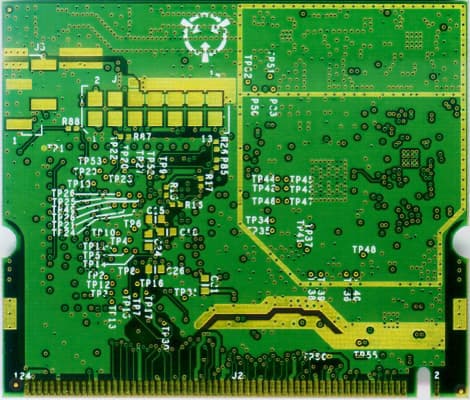
HN2WAMIG2
Nov 18, 2003802MIG2
Equipment Class
DTS - Digital Transmission System
HN2SB555-2
Sep 04, 2003SB555 Radio in 700C
Equipment Class
PCE - PCS Licensed Transmitter held to ear
HN22011B-2
Jul 28, 20032011B Radio in 700C
Equipment Class
DTS - Digital Transmission System