I4U23VT2LMicrowave Transmitter
Integrated Microwave Technologies, LLC.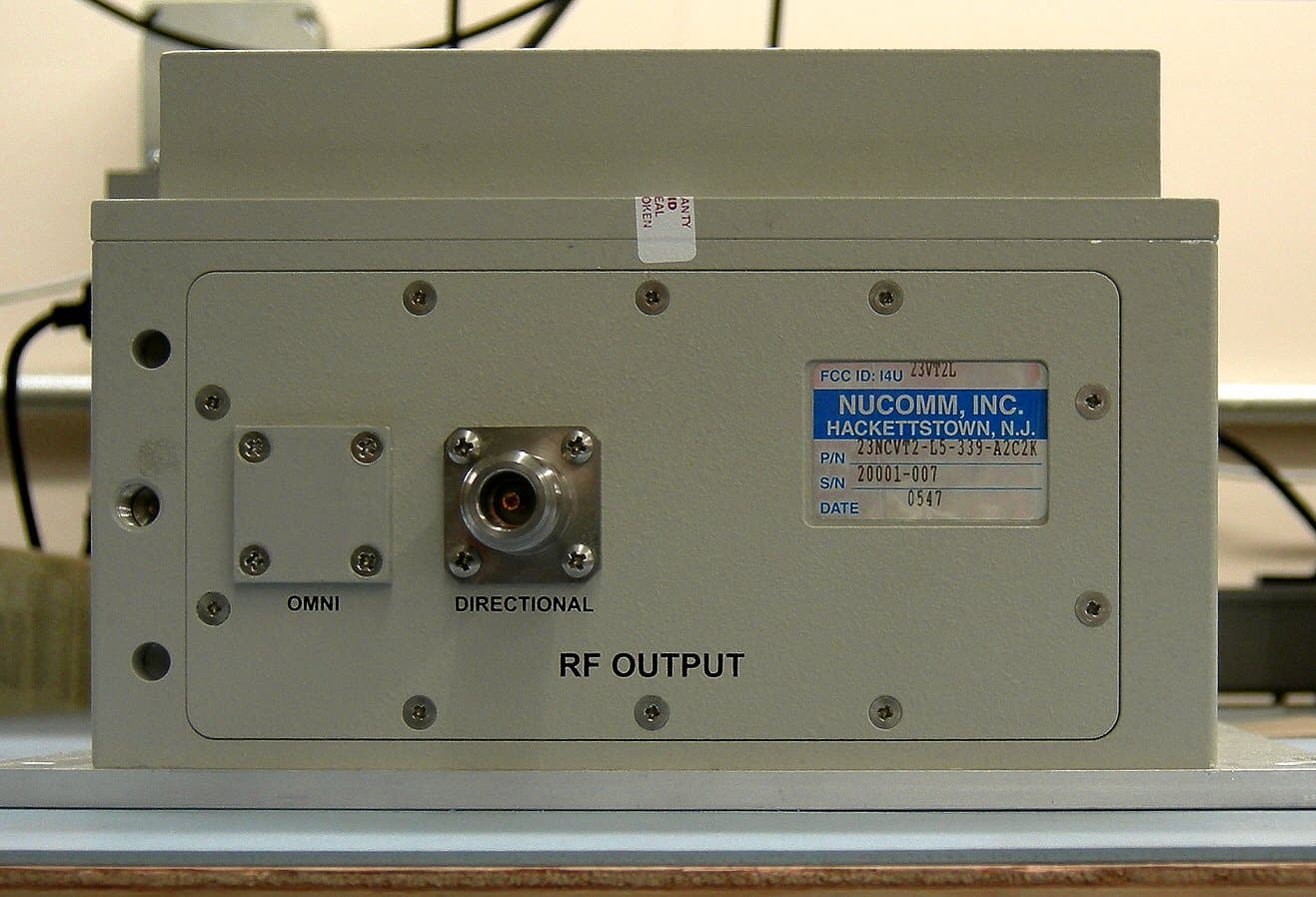
Click to zoom
Application Details
- Equipment Class
- TBC - Licensed Broadcast Station Transmitter
- Date of Grant
- Jun 01, 2006
- Application Purpose
- Original Equipment
- Date of Application
- Jun 01, 2006
- Equipment Note
- Microwave Transmitter
- Frequency Range
- 1990.00000000 - 2500.00000000
- Country
- United States
Documents & Files
Document Text
Text extracted from the exhibit documents filed with the FCC. Open a document above to read the original.
Cover Letter(s)
101 Bilby Rd Hackettstown, NJ 07840 USA (908) 852-3700 www.nucomm.com Confidentiality Request Pertaining to Request for Certification of FCC ID: I4U23VT2L Nucomm hereby respectfully requests confidentiality of certain materials pursuant to published FCC guidelines, with respect to our Request for Certification of FCC ID: I4U23VT2L, in accordance with FCC Sections 0.459(b), and 0.457(d) Nucomm has submitted a Technical Report, as required by FCC guidelines, in conjunction with the Request for Certification. Certain parts of this Technical Report and/or the attendant submittals contain information that are trade secrets and are requested to be withheld from public inspection. The attachments and/or exhibits, henceforth collectively “Materials”, designated as (a) Schematics, including descriptions of circuitry, (b) Bill(s) of Materials, (c) Block Diagrams, and (d) Photos of Component and Trace Layout are requested to remain confidential. These Materials are listed below, along with reference to their location in the Request for Certification, for ease of identification: In “NCVT2 Certification Report.doc” Page 7-10 Section 8: Description of circuitry and devices Page 8 Figure 1: Transmitter Block Diagram Page 9 Figure 2: FM Modulator Block Diagram Page 10 Figure 3: Digital Modulator Page 25 Figure 15: Top view of 23NCVT2-L5-339-A2C2K Control unit with cover removed Page 26 Figure 16: Top view of 23NCVT2-L5-339-A2C2K RF unit with cover removed Page 27 Figure 17: Final Power Amplifier from RF unit with cover removed These materials contain commercial trade secret information that would reveal our unique proprietary system design which is a result of our proprietary Research and Development. These materials comprise information that differentiates our products from those of our significant market competition, and which allow us operate in the very competitive market for this product. These materials, if released, would result in substantial competitive harm due to unlicensed copying of our proprietary design(s) in whole or in part. To protect these materials, Nucomm does not release them to the public, and protects them from unauthorized disclosure by third parties via the execution of Non-Disclosure Agreement’s. In respect to the internal photo of the Final Power Amplifier, Nucomm feels that additional justification for confidentiality exists due to the fact that the amplifier circuit board(s) are mounted inside a sealed component that can sustain damage upon opening, and that said component itself is mounted inside an enclosure that the end-user may not readily open, and that so opening would nullify any equipment warranty since the equipment is only serviceable by Nucomm or our designated technicians, and that the internal image(s) of the amplifier would provide any reasonably savvy RF engineer the means to replicate the amplifier and result in substantial competitive harm to Nucomm. Nucomm requests that these materials be withheld from public inspection in perpetuity due to the possibility and likelihood that the designs will be utilized, in whole or in part, by Nucomm as the basis for future products which would likewise be subject to the same competitor interest. John B Payne IV, Chief Engineer Nucomm, Inc.
External Photos
Rear View of 23NCVT2-L5-339-A2C2K Control Drawer Front View of 23NCVT2-L5-339-A2C2K Control Drawer RF Head output RF Head Connector side
ID Label/Location Info
. FCC Equipment Identification Plate
ID Label/Location Info
Retlif Testing Laboratories Test Report Number R-11200, FCC ID: I4U23VT2L Control Drawer FCC Label Location Retlif Testing Laboratories Test Report Number R-11200, FCC ID: I4U23VT2L RF Head FCC Label Location
Test Report
Nucomm NCVT2 FCC Technical Report (23NCVT2-L5-339-A2C2K) Date: 4/6/06 Revision: 1.6 Page 1 of 19 Nucomm - FCC Certification Report Newscaster VT2 Digital/Analog ENG/OB Van Transmitter 23NCVT2-L5-339-A2C2K (Per CFR TITLE 47, PART 2, SUB-PART J) Nucomm, Inc. 101 Bilby Road Hackettstown, NJ 07840 Tel: 908 852-3700 FAX: 908 813-0399 www.Nucomm.com Nucomm NCVT2 FCC Technical Report (23NCVT2-L5-339-A2C2K) Date: 4/6/06 Revision: 1.6 Page 2 of 19 PROPRIETARY INFORMATION This document contains proprietary information, which shall not be reproduced or transferred to other documents or disclosed to others or used for manufacturing or any other purpose without prior written permission of: Nucomm, INCORPORATED 101 Bilby Road Hackettstown, NJ 07840 Specifications are subject to change in order to allow for the introduction of design improvements Nucomm NCVT2 FCC Technical Report (23NCVT2-L5-339-A2C2K) Date: 4/6/06 Revision: 1.6 Page 3 of 19 Table of Contents 1 APPLICANTS FULL NAME AND ADDRESS (1) ..................................................................................................................... 6 2 FCC IDENTIFIER (2) ................................................................................................................................................................... 6 3 INSTALLATION AND OPERATING INSTRUCTIONS TO BE FURNISHED BY THE USER (3) ................................... 6 4 EMISSION (4), FREQUENCY RANGE (5), & RANGE OF OPERATING POWER (6) ...................................................... 6 5 MAXIMUM POWER RATING AS DEFINED IN THE APPLICABLE PART(S) OF THE RULES (7) ............................. 7 6 DC VOLTAGES & CURRENTS (8) ........................................................................................................................................... 7 7 TUNE-UP PROCEDURE OVER THE POWER RANGE, OR AT SPECIFIC OPERATING POWER LEVELS (9)........ 7 8 EQUIPMENT IDENTIFICATION (11)....................................................................................................................................... 7 9 PHOTOGRAPHS (8X10 INCH) OF THE EQUIPMENT (12). ................................................................................................. 8 10 DIGITAL MODULATION TECHNIQUES (13) ........................................................................................................................ 8 11 DATA REQUIRED BY §§2.1046 THROUGH 2.1057, INCLUSIVE, MEASURED IN ACCORDANCE WITH THE PROCEDURES SET OUT IN §2.1041 (14). .......................................................................................................................................... 8 11.1 RF POWER OUTPUT ( 2.1046) .................................................................................................................................................. 9 11.2 MODULATION CHARACTERISTICS (2.1047) ........................................................................................................................... 10 11.2.1 Video Modulation:....................................................................................................................................................... 10 11.2.2 Video Frequency Response ......................................................................................................................................... 11 11.2.3 Audio Modulation........................................................................................................................................................ 12 11.3 OCCUPIED BANDWIDTH (2.1049) ........................................................................................................................................... 13 11.4 SPURIOUS EMISSION AT ANTENNA TERMINALS (2.1059)....................................................................................................... 15 11.5 FIELD STRENGTH OF SPURIOUS RADIATION (2.1053).............................................................................................................. 15 11.6 FREQUENCY STABILITY (2.1055) ........................................................................................................................................... 15 Nucomm NCVT2 FCC Technical Report (23NCVT2-L5-339-A2C2K) Date: 4/6/06 Revision: 1.6 Page 4 of 19 List of Tables Table 1 Revision History ....................................................................................................................... 5 Table 2: Analog and Digital Power Levels ............................................................................................ 6 Table 3: Maximum DC voltage and currents ......................................................................................... 7 Table 4 - Test Equipment Used ............................................................................................................ 8 Table 5 Power Output: 1990-2500 MHz (current freqs) ........................................................................ 9 Table 6 Power Output: 2031.5-2500 MHz (BAS relo freqs) .................................................................. 9 Table 7: 17 MHz channel spacing with +/- 4 MHz FM deviation ......................................................... 11 Table 8: 12 MHz channel spacing with +/- 3 MHz FM deviation (BAS relo frequencies)..................... 11 Table 9: 17 MHz channel spacing with +/- 4 MHz FM deviation ......................................................... 11 Table 10: 12 MHz channel spacing with +/- 3 MHz FM deviation (BAS relo frequencies)................... 11 Table 11: 17 MHz channel spacing with +/- 4 MHz FM deviation ....................................................... 12 Table 12: 12 MHz channel spacing with +/- 3 MHz FM deviation (BAS relo frequencies)................... 13 Table 13: Occupied Bandwidth Figure Reference (17 MHz spacing).................................................. 14 Table 14: Occupied Bandwidth figure reference (12 MHz spacing) .....…
Text truncated - open the document above for the full version.
Test Report
Applicant: Nucomm, Inc. FCC ID: I4U23VT2L Retlif Testing Laboratories Report No.: R-11200 GENERAL INFORMATION REQUIREMENTS Paragraph 2.983(a) Name of Applicant: Nucomm, Inc. Address of Applicant: 101 Bilby Road Hackettstown, NJ 07840 Name of Manufacturer: Nucomm, Inc. Paragraph 2.983(b) Equipment Identification: FCC ID: I4U23VT2L Applicant: Nucomm, Inc. FCC ID: I4U23VT2L Retlif Testing Laboratories Report No.: R-11200 Para. 2.1053 FIELD STRENGTH of SPURIOUS EMISSIONS, EFFECTIVE RADIATED POWER Applicant: Nucomm, Inc. FCC ID: I4U23VT2L Retlif Testing Laboratories Report No.: R-11200 FIELD STRENGTH of SPURIOUS EMISSIONS, EFFECTIVE RADIATED POWER (Para. 2.1053) A. Measurement Procedure: The spurious emissions of the transmitter from 10 kHz to 40 GHz were measured in accordance with TIA/EIA603, Paragraph 2.2.1.2 as described below: The transmitter under test was placed on an 80-cm high non-metallic table on the Open Air Test Site with its antenna terminated into a shielded load. A receive antenna was placed three meters away from the transmitter. The turntable was rotated 360 degrees and the receive antenna was raised and lowered from 1 to 4 meters until a maximum reading was obtained at each spurious emission detected. This reading was recorded. The transmitter under test was replaced with a dipole (or equivalent antenna) and signal generator. The signal generator was set to the frequency for the spurious emission. The level of the signal generator was increased until the level was equal to that previously measured. The required input level from the signal generator in dBm was recorded and the antenna gain (in dB) of the transmit antenna was added. This was the Effective Radiated Power of the spurious emission. Setup of the test is shown below: Spectrum Analyzer Test Sample 3M 4M Broadband Antenna Pre Amplifier Applicant: Nucomm, Inc. FCC ID: I4U23VT2L Retlif Testing Laboratories Report No.: R-11200 EQUIPMENT LISTS TIA/EIA-603-1992, Section 2.2.12, Radiated Spurious Emissions (30 MHz to 26 GHz) EN Type Manufacturer Description Model No. Cal Date Due Date 067 Open Area Test Site Retlif 3 Meter RNY 10/1/2003 10/1/2006 1007 10.0 dB Attenuator Narda DC - 18 GHz 776C-10 11/29/2005 11/29/2006 1009 30.0 dB Attenuator Narda DC - 18 GHz 776C-30 11/29/2005 11/29/2006 128C Double Ridge Guide Eaton Corporation 1 GHz - 18 GHz 96001 8/17/2005 8/17/2006 129D High Gain Horn Antenna Microlab/FXR 12.4 GHz - 18 GHz Y638A 9/16/2005 9/16/2006 129F High Gain Horn Antenna Microlab/FXR 18 GHz - 26.5 GHz K638A 9/16/2005 9/16/2006 141 Spectrum Analyzer Hewlett Packard 100 Hz - 40 GHz 8566B 8/28/2005 2/28/2006 141A Graphics Plotter Hewlett Packard N/A 7470A 2/9/2006 2/9/2007 141B Quasi-Peak Adaptor Hewlett Packard 100 Hz - 1 GHz 85650A 8/28/2005 2/28/2006 141C Cable Retlif 1 GHz ~ 18 GHz 1 METER, BLUE 1/4/2006 1/4/2007 141D Cable Retlif 1 GHz ~ 18 GHz 10 METER, BLACK 1/4/2006 1/4/2007 399 Log Periodic Antenna Antenna Research 1 GHz - 12 GHz LPD-112 9/28/2005 9/28/2006 420 Amplifier Hewlett Packard 2.0 GHz - 18 GHz 11975A 10/31/2005 10/31/2006 421 Harmonic Mixer Hewlett Packard 18 GHz - 26.5 GHz 11970K 9/29/2003 9/29/2006 450A Tuned Dipole Antenna Empire Devices 30 - 140 MHz DM-105-T1 8/12/2003 8/12/2006 450B Tuned Dipole Antenna Empire Devices 140 - 400 MHz DM-105-T2 8/12/2003 8/12/2006 523 Biconilog Electro-Mechanics 26 - 2000 MHz 3142B 11/10/2005 11/10/2006 543 Preamplifier Hewlett Packard 1.0 GHz - 26.5 GHz 8449B 9/9/2005 9/9/2007 648A Power Meter Boonton Electronics 10 kHz - 100 GHz 4232A 6/7/2005 6/7/2006 649 Power Sensor Boonton Electronics 10 kHz - 8 GHz 51011-EMC 4/20/2005 4/20/2006 712A Cable Retlif 10 kHz - 18 GHz R&S Analyzer 1/21/2005 7/21/2006 712B Cable Retlif 10 kHz - 18 GHz R&S Analyzer 1/21/2005 7/21/2006 711 Microwave Sweeper Gigatronics 500 MHz - 20 GHz GT9000S/.5-20 10/18/2005 10/18/2006 723 H.P. Filter Mini-Circuits 1 GHz BHP-1000 7/20/2005 7/20/2006 Applicant: Nucomm, Inc. FCC ID: I4U23VT2L Retlif Testing Laboratories Report No.: R-11200 TEST SETUP PHOTOGRAPHS Applicant: Nucomm, Inc. FCC ID: I4U23VT2L Retlif Testing Laboratories Report No.: R-11200 Applicant: Nucomm, Inc. FCC ID: I4U23VT2L Retlif Testing Laboratories Report No.: R-11200 RADIATED SPURIOUS EMISSIONS TEST DATA Applicant: Nucomm, Inc. FCC ID: I4U23VT2L Retlif Testing Laboratories Report No.: R-11200 Test Method: TIA / EIA-603-1992, Section 2.2.12, Radiated Spurious Emissions (30 MHz – 26 GHz) Customer: Nucomm, Inc. Job No. R-11200 Test Sample: Digital/Analog ENG/OB Van Transmitter Serial No. 20001-007 Model No.: NEWSCASTER VT2 FCC ID: I4U23VT2L Operating Mode: Color bars plus audio, High power, Channel 1, Digital COFDM Modulation, 17 MHZ channels Transmitting at 1999 MHz. Technician: R. Soodoo Date: February 14, 2006. Notes: Test Distance: 3 Meters Temp: 15°C Humidity: 22% Detector: Peak Limit = (43 + 10 log P) down from fundamental level = -13dBm Test Freq. Antenna Position EUT Orientation Meter Readings Signal Generator Reading Gain Above Isotropic Cable Factor ERP LIMIT MHz (V/H) meter Degrees dBuV dBm dB dB dBm dBm 30.00 -13.0 | | | | | | | | | | 135.0 V / 1.0 315.0 75.1 -26.5 2.2 0.9 -23.4 | 162.0 V / 1.0 158.0 75.1 -24.8 2.2 1.0 -21.6 | 175.0 V / 1.0 315.0 63.2 -34.9 2.2 0.9 -31.8 | 189.0 V / 1.0 90.0 59.4 -36.7 2.2 0.9 -33.6 | 332.0 H / 1.0 158.0 60.6 -33.9 2.2 1.3 -30.4 | 405.0 H / 1.0 225.0 60.5 -33.3 2.2 2.2 -28.9 | 3848.0 V / 1.0 158.0 53.1 -41.4 7.0 4.5 -29.9 | 3852.0 H / 1.0 158.0 57.8 -36.3 7.0 4.5 -24.8 | | | | | | | | | | | | | | | | | | | | | | | | | 26000.00 -13.0 The EUT was placed on a tabletop, and the radiated output level was measured with a receive antenna. After the level was maximized, the EUT was replaced with a transmit antenna and a signal generator. The level of the generator was raised until it matched the level recorded from the EUT and this plus the antenna gain and cable factor was considered the output power. All emissions not recorded were more than 20 dB below the limit. Applicant: Nucomm, Inc. FC…
Text truncated - open the document above for the full version.
Test Report
Retlif Testing Laboratories Test Report Number R-11200, FCC ID: I4U23VT2L NOTES: § 74.637 Emissions and emission limitations. (a) The mean power of emissions shall be attenuated below the mean transmitter power (PMEAN) in accordance with the following schedule: (1) When using frequency modulation: (i) On any frequency removed from the assigned (center) frequency by more than 50% up to and including 100% of the authorized bandwidth: At least 25 dB in any 100 kHz reference bandwidth (BREF); (ii) On any frequency removed from the assigned (center) frequency by more than 100% up to and including 250% of the authorized bandwidth: At least 35 dB in any 100 kHz reference bandwidth; (iii) On any frequency removed from the assigned (center) frequency by more than 250% of the authorized bandwidth: At least 43+10 log10 (PMEAN in watts) dB, or 80 dB, whichever is the lesser attenuation, in any 100kHz reference bandwidth. (2) For Digital Modulation: (i) For operating frequencies below 15 GHz, in any 4 kHz reference bandwidth (BREF), the center frequency of which is removed from the assigned frequency by more than 50 percent up to and including 250 percent of the authorized bandwidth: As specified by the following equation but in no event less than 50 decibels: A = 35 + 0.8 (G _ 50) + 10 Log10 B. (Attenuation greater than 80 decibels is not required.) Where: A = Attenuation (in decibels) below the mean output power level. G = Percent removed from the carrier frequency. B = Authorized bandwidth in megahertz. Compliance curves drawn at A(dB)=35+ 0.8(G-50) + 10 LOG B – 13.9 Where: A= Attenuation required G= percent of bandwidth removed from carrier B=authorized Bandwidth in Mhz Compliance curves include the compliance factor for measurments made with a 100KHz resolution bandwidth which is: 10 log ( B RES / B REF ) = 10log ( 4E3 / 100E3) = -13.9db Reference Level Offset Note: The following Measurements where made with the transmitter output connected to a 20 db directional coupler connected to the spectrum analyzer by a three foot coaxial cable. The thru path of the directional coupler was connected directly to a 30 db attenuator connected to a power meter used to monitor the output power. A 21dB reference level offset was entered into the spectrum analyzer in order to show the true output level of the Transmitter. Retlif Testing Laboratories Test Report Number R-11200, FCC ID: I4U23VT2L Figure 33 Occupied Bandwidth measurement; Modulation overlaying Mask and measured Power Bandwidth. COFDM modulation, 8 MHz 16QAM color Bars with Audio Channel 1 BAS relo frequency Retlif Testing Laboratories Test Report Number R-11200, FCC ID: I4U23VT2L Figure 34 Occupied Bandwidth measurement; Modulation overlaying Mask and measured Power Bandwidth. COFDM modulation, 8 MHz 16 QAM, Color Bars with Audio Retlif Testing Laboratories Test Report Number R-11200, FCC ID: I4U23VT2L Channel 2 BAS relo frequency Figure 35 Occupied Bandwidth measurement; Modulation overlaying Mask and measured Power Bandwidth. COFDM modulation, 8 MHz 16QAM, Color Bars with Audio Retlif Testing Laboratories Test Report Number R-11200, FCC ID: I4U23VT2L Channel 6 BAS relo frequency Figure 36 Occupied Bandwidth measurement; Modulation overlaying Mask and measured Power Bandwidth. COFDM modulation, 8 MHz 16QAM, Color Bars with Audio Retlif Testing Laboratories Test Report Number R-11200, FCC ID: I4U23VT2L Channel 7 BAS relo frequency Figure 37 Occupied Bandwidth measurement; Modulation overlaying Mask and measured Power Bandwidth. FM , +/- 3 MHz Deviation ,Color Bars with Audio Retlif Testing Laboratories Test Report Number R-11200, FCC ID: I4U23VT2L Channel 1 BAS relo frequency Figure 38 Retlif Testing Laboratories Test Report Number R-11200, FCC ID: I4U23VT2L Occupied Bandwidth measurement; Modulation overlaying Mask and measured Power Bandwidth. FM , +/- 3 MHz Deviation ,Color Bars with Audio Channel 2 BAS relo frequency Retlif Testing Laboratories Test Report Number R-11200, FCC ID: I4U23VT2L Figure 39 Occupied Bandwidth measurement; Modulation overlaying Mask and measured Power Bandwidth. FM , +/- 3 MHz Deviation ,Color Bars with Audio Channel 6 BAS relo frequency Figure 40b Retlif Testing Laboratories Test Report Number R-11200, FCC ID: I4U23VT2L Occupied Bandwidth measurement; Modulation overlaying Mask and measured Power Bandwidth. FM , +/- 3 MHz Deviation ,Color Bars with Audio Channel 7 BAS relo frequency
Test Report
Retlif Testing Laboratories Test Report Number R-11200, FCC ID: I4U23VT2L NOTES: § 74.637 Emissions and emission limitations. (a) The mean power of emissions shall be attenuated below the mean transmitter power (PMEAN) in accordance with the following schedule: (1) When using frequency modulation: (i) On any frequency removed from the assigned (center) frequency by more than 50% up to and including 100% of the authorized bandwidth: At least 25 dB in any 100 kHz reference bandwidth (BREF); (ii) On any frequency removed from the assigned (center) frequency by more than 100% up to and including 250% of the authorized bandwidth: At least 35 dB in any 100 kHz reference bandwidth; (iii) On any frequency removed from the assigned (center) frequency by more than 250% of the authorized bandwidth: At least 43+10 log10 (PMEAN in watts) dB, or 80 dB, whichever is the lesser attenuation, in any 100kHz reference bandwidth. (2) For Digital Modulation: (i) For operating frequencies below 15 GHz, in any 4 kHz reference bandwidth (BREF), the center frequency of which is removed from the assigned frequency by more than 50 percent up to and including 250 percent of the authorized bandwidth: As specified by the following equation but in no event less than 50 decibels: A = 35 + 0.8 (G _ 50) + 10 Log10 B. (Attenuation greater than 80 decibels is not required.) Where: A = Attenuation (in decibels) below the mean output power level. G = Percent removed from the carrier frequency. B = Authorized bandwidth in megahertz. Compliance curves drawn at A(dB)=35+ 0.8(G-50) + 10 LOG B – 13.9 Where: A= Attenuation required G= percent of bandwidth removed from carrier B=authorized Bandwidth in Mhz Compliance curves include the compliance factor for measurments made with a 100KHz resolution bandwidth which is: 10 log ( B RES / B REF ) = 10log ( 4E3 / 100E3) = -13.9db Reference Level Offset Note: The following Measurements where made with the transmitter output connected to a 20 db directional coupler connected to the spectrum analyzer by a three foot coaxial cable. The thru path of the directional coupler was connected directly to a 30 db attenuator connected to a power meter used to monitor the output power. A 21dB reference level offset was entered into the spectrum analyzer in order to show the true output level of the Transmitter. Retlif Testing Laboratories Test Report Number R-11200, FCC ID: I4U23VT2L Figure 13 Occupied Bandwidth measurement; Modulation overlaying Mask and measured Power Bandwidth. COFDM modulation, 8 MHz 16QAM, Color Bars with Audio Channel 1 Retlif Testing Laboratories Test Report Number R-11200, FCC ID: I4U23VT2L Figure 14 Occupied Bandwidth measurement; Modulation overlaying Mask and measured Power Bandwidth. COFDM modulation, 8 MHz 16QAM, Color Bars with Audio Retlif Testing Laboratories Test Report Number R-11200, FCC ID: I4U23VT2L Channel 2 Figure 15 Occupied Bandwidth measurement; Modulation overlaying Mask and measured Power Bandwidth. COFDM modulation, 8 MHz 16QAM, Color Bars with Audio Retlif Testing Laboratories Test Report Number R-11200, FCC ID: I4U23VT2L Channel 3 Figure 16 Occupied Bandwidth measurement; Modulation overlaying Mask and measured Power Bandwidth. COFDM modulation, 8 MHz 16QAM, Color Bars with Audio Retlif Testing Laboratories Test Report Number R-11200, FCC ID: I4U23VT2L Channel 4 Figure 17 Retlif Testing Laboratories Test Report Number R-11200, FCC ID: I4U23VT2L Occupied Bandwidth measurement; Modulation overlaying Mask and measured Power Bandwidth. COFDM modulation, 8 MHz 16QAM, Color Bars with Audio Channel 5 Retlif Testing Laboratories Test Report Number R-11200, FCC ID: I4U23VT2L Figure 18 Occupied Bandwidth measurement; Modulation overlaying Mask and measured Power Bandwidth. COFDM modulation, 8 MHz 16QAM, Color Bars with Audio Channel 6 Retlif Testing Laboratories Test Report Number R-11200, FCC ID: I4U23VT2L Figure 19 Occupied Bandwidth measurement; Modulation overlaying Mask and measured Power Bandwidth. COFDM modulation, 8 MHz 16QAM, Color Bars with Audio Channel 7 Retlif Testing Laboratories Test Report Number R-11200, FCC ID: I4U23VT2L Figure 20 Occupied Bandwidth measurement; Modulation overlaying Mask and measured Power Bandwidth. COFDM modulation, 8 MHz 16QAM, Color Bars with Audio Channel 8 Retlif Testing Laboratories Test Report Number R-11200, FCC ID: I4U23VT2L Figure 21 Occupied Bandwidth measurement; Modulation overlaying Mask and measured Power Bandwidth. COFDM modulation, 8 MHz 16QAM, Color Bars with Audio Channel 9 Retlif Testing Laboratories Test Report Number R-11200, FCC ID: I4U23VT2L Figure 22 Occupied Bandwidth measurement; Modulation overlaying Mask and measured Power Bandwidth. COFDM modulation, 8 MHz 16QAM, Color Bars with Audio Channel 10 Retlif Testing Laboratories Test Report Number R-11200, FCC ID: I4U23VT2L Figure 23 Occupied Bandwidth measurement; Modulation overlaying Mask and measured Power Bandwidth. FM , +/- 4 MHz Deviation ,Color Bars with Audio Channel 1 Retlif Testing Laboratories Test Report Number R-11200, FCC ID: I4U23VT2L Figure24 Occupied Bandwidth measurement; Modulation overlaying Mask and measured Power Bandwidth. FM , +/- 4 MHz Deviation ,Color Bars with Audio Channel 2 Retlif Testing Laboratories Test Report Number R-11200, FCC ID: I4U23VT2L Figure 25b Occupied Bandwidth measurement; Modulation overlaying Mask and measured Power Bandwidth. FM , +/- 4 MHz Deviation ,Color Bars with Audio Channel 3 Retlif Testing Laboratories Test Report Number R-11200, FCC ID: I4U23VT2L Figure 26 Occupied Bandwidth measurement; Modulation overlaying Mask and measured Power Bandwidth. FM , +/- 4 MHz Deviation ,Color Bars with Audio Channel 4 Retlif Testing Laboratories Test Report Number R-11200, FCC ID: I4U23VT2L Figure 27 Occupied Bandwidth measurement; Modulation overlaying Mask and measured Power Bandwidth. FM , +/- 4 MHz Deviation ,Color Bars with Audio Channel 5 Retlif Testing Laboratories Test Report Number R-11200, FCC ID: I4U23VT…
Text truncated - open the document above for the full version.
Test Report
Retlif Testing Laboratories Test Report Number R-11200, FCC ID: I4U23VT2L Figure 41 : Directional Antenna Port Conducted Emissions 17 Mhz channels Modulation: Digital COFDM Input signal : color bars plus audio High Power Mode Channel 1 Note 1: Fundamental frequency exempt from -13dBm. . Retlif Testing Laboratories Test Report Number R-11200, FCC ID: I4U23VT2L Figure 42 : Directional Antenna Port Conducted Emissions 17 Mhz channels Modulation: Digital COFDM Input signal : color bars plus audio High Power Mode Channel 7 Note 1: Fundamental frequency exempt from -13dBm. . Retlif Testing Laboratories Test Report Number R-11200, FCC ID: I4U23VT2L Figure 43 : Directional Antenna Port Conducted Emissions 17 Mhz channels Modulation: Digital COFDM Input signal : color bars plus audio High Power Mode Channel 10 Note 1: Fundamental frequency exempt from -13dBm. Retlif Testing Laboratories Test Report Number R-11200, FCC ID: I4U23VT2L Figure 44 : Directional Antenna Port Conducted Emissions 17 Mhz channels Modulation: FM Input signal : color bars plus audio High Power Mode Channel 1 Note 1: Fundamental frequency exempt from -13dBm. Retlif Testing Laboratories Test Report Number R-11200, FCC ID: I4U23VT2L Figure 45: Directional Antenna Port Conducted Emissions 17 MHz channels Modulation: FM Input signal: color bars plus audio High Power Mode Channel 7 Note 1: Fundamental frequency exempt from -13dBm. Retlif Testing Laboratories Test Report Number R-11200, FCC ID: I4U23VT2L Figure 46: Directional Antenna Port Conducted Emissions 17 Mhz channels Modulation: FM Input signal : color bars plus audio High Power Mode Channel 10 Note 1: Fundamental frequency exempt from -13dBm. . Retlif Testing Laboratories Test Report Number R-11200, FCC ID: I4U23VT2L Figure 47 : Directional Antenna Port Conducted Emissions New BAS relo channels 12 Mhz channel spacing plan Modulation: Digital COFDM Input signal : color bars plus audio High Power Mode Channel 1 Note 1: Fundamental frequency exempt from -13dBm. Retlif Testing Laboratories Test Report Number R-11200, FCC ID: I4U23VT2L Figure 48 : Directional Antenna Port Conducted Emissions New BAS relo channels 12 Mhz channel spacing plan Modulation: Digital COFDM Input signal: color bars plus audio High Power Mode Channel 2 Note 1: Fundamental frequency exempt from -13dBm. . Retlif Testing Laboratories Test Report Number R-11200, FCC ID: I4U23VT2L Figure 49 : Directional Antenna Port Conducted Emissions New BAS relo channels 12 Mhz channel spacing plan Modulation: Digital COFDM Input signal: color bars plus audio High Power Mode Channel 3 Note 1: Fundamental frequency exempt from -13dBm. . Retlif Testing Laboratories Test Report Number R-11200, FCC ID: I4U23VT2L Figure 50 : Directional Antenna Port Conducted Emissions New BAS relo channels 12 Mhz channel spacing plan Modulation: Digital COFDM Input signal: color bars plus audio High Power Mode Channel 4 Note 1: Fundamental frequency exempt from -13dBm. . Retlif Testing Laboratories Test Report Number R-11200, FCC ID: I4U23VT2L Figure 51: Directional Antenna Port Conducted Emissions New BAS relo channels 12 Mhz channel spacing plan Modulation: Digital COFDM Input signal: color bars plus audio High Power Mode Channel 5 Note 1: Fundamental frequency exempt from -13dBm. Retlif Testing Laboratories Test Report Number R-11200, FCC ID: I4U23VT2L Figure 52 : Directional Antenna Port Conducted Emissions New BAS relo channels 12 Mhz channel spacing plan Modulation: Digital COFDM Input signal: color bars plus audio High Power Mode Channel 6 Note 1: Fundamental frequency exempt from -13dBm. . Retlif Testing Laboratories Test Report Number R-11200, FCC ID: I4U23VT2L Figure 53 : Directional Antenna Port Conducted Emissions New BAS relo channels 12 Mhz channel spacing plan Modulation: Digital COFDM Input signal: color bars plus audio High Power Mode Channel 7 Note 1: Fundamental frequency exempt from …
Text truncated - open the document above for the full version.
Contact Information
Applicant
Stephen Kitko(Compliance Engineer)
Test Firm
Retlif Testing LaboratoriesMichael Bozza
Technical Specifications
| # | Rule Parts | Frequency Range | Power Output | Emission | Tolerance |
|---|---|---|---|---|---|
| 4 | 74 | 1.99 GHz - 2.50 GHz | 5 W | 12M0D9W | 0.005 % |
Other Applications from Integrated Microwave Technologies, LLC.

I4U-25VST-AMP
Nov 15, 2015Very Small Transmitter 25VST-AMP
Equipment Class
TNB - Licensed Non-Broadcast Station Transmitter
I4U-23WBMLT
Feb 27, 2013WIDEBAND MICROLITE HD COFDM TRANSMITTER 23WBMLT
Equipment Class
DTS - Digital Transmission System
I4U-65SKTX-71
Feb 25, 2013Skymaster TX HD/SD COFDM Transmitter 65SKTX
Equipment Class
TNB - Licensed Non-Broadcast Station Transmitter
I4U-25VST
Feb 29, 2012Ultra Compact SD COFDM Transmitter 25VST
Equipment Class
DTS - Digital Transmission System
I4U-58MLT
Sep 01, 2011MicroLITE HD Transmitter Model NO. 58MLT
Equipment Class
DTS - Digital Transmission System