J26-4859300114LTE PCI-e Moudular
CalAmp Corp.
Click to zoom
Application Details
- Equipment Class
- JBP - Part 15 Class B Computing Device Peripheral
- Date of Grant
- Feb 24, 2014
- Application Purpose
- Original Equipment
- Date of Application
- Feb 20, 2014
- Equipment Note
- LTE PCI-e Moudular
- Company
- CalAmp Corp.
- Country
- United States
Documents & Files
Document Text
Text extracted from the exhibit documents filed with the FCC. Open a document above to read the original.
Users Manual
LTE Mini PCI-e Module User Manual Rev:R1.2 1 LTE Mini PCI-e Module—LP 15 User Manual V2.0 LTE Mini PCI-e Module User Manual Rev:R1.2 2 Revision History Revision Changes Date V1.0 Initial Draft 2012-08-19 V2.0 Revise 2012-12-06 LTE Mini PCI-e Module User Manual Rev:R1.2 3 Index REVISION HISTORY ......................................................................................................................................... 2 1 INTRODUCTION ....................................................................................................................................... 4 2 MECHANICAL INFORMATION ............................................................................................................. 4 3 SPECIFICATIONS ..................................................................................................................................... 5 3.1 RF PERFORMANCE ................................................................................................................................. 6 3.1.1 RX Performance ................................................................................................................................ 6 3.1.2 TX Performance ................................................................................................................................ 6 3.1.3 UIM Card ......................................................................................................................................... 7 3.1.4 USB PORT ........................................................................................................................................ 7 3.1.5 RF Subsystem .................................................................................................................................... 7 3.2 FULL-MINI PCI EXPRESS CARD PCB DETAILS ...................................................................................... 7 4 REGULATORY AND SAFETY INFORMATION .................................................................................. 8 4.1 REGULATORY APPROVALS..................................................................................................................... 8 4.1.1 Transmitter ....................................................................................................................................... 8 4.1.2 Receiver ............................................................................................................................................ 8 4.1.3 FCC Compliance .............................................................................................................................. 8 4.1.4 Labeling ............................................................................................................................................ 9 4.2 RF ENERGY EXPOSURE INFORMATION .................................................................................................. 9 5 INSTALLATION GUIDELINES ............................................................................................................. 10 5.1 INTRODUCTION .................................................................................................................................... 10 5.2 APPLICATION TYPE .............................................................................................................................. 10 LTE Mini PCI-e Module User Manual Rev:R1.2 4 1 Introduction LP15 is Mini-PCIE interface wireless LTE module base on LTE technology, which has high performance and durability and could be used in CPE, POS machine, electronic metering, security camera and medical care area. It has standard Mini PCI-e interface which is easy to be integrated. Mode Description LP15 Support Band14 2 Mechanical Information Items Specification Size 51(L)x30(W)x4.5(H) mm Mini PCI-e Full Mini PCI-e LTE Mini PCI-e Module User Manual Rev:R1.2 5 3 Specifications LTE Features Support Band Band14 LTE Standard 3GPP Release 8 UE Category Category 3 Bandwidth 5MHz,10MHz Interfaces Mini PCI-e 52PIN Mini PCI-e USB interface USB 2.0 high speed UART Support USIM interface 1.8V or 3.0V USIM Antenna port Dual-Antenna connector RF Connectors 20279-001E-01(I-PEX) Operating voltage 3.3 V Power supply Electrical Power 3.3 Vdc Power Consumption 3.5 Watts maximum RF performance Maximum Output Power 22±1dBm TX Performance See details TX performance RX Performance See details RX performance Mechanical Module Interface 52 pin Full-Mini PCI Express Card interface Dimensions 30x 51x4.6mm Environmental Operation Temperature -20°C ~ 55°C Storage Temperature -40°C ~ 85°C Operation Humidity 5% ~ 95% LTE Mini PCI-e Module User Manual Rev:R1.2 6 3.1 RF Performance 3.1.1 RX Performance Item Description Frequency range 758MHz-768MHz Reference sensitivity level (TDD) <-99.3dBm@BW=5MHz <-96.3dBm@BW=10MHz <-94.5dBm@BW=15MHz <-93.3dBm@BW=20MHz Maximum input level >-25.7dBm Spurious emissions <-57 dBm@100KHz 30MHz ≤ f < 1GHz <-47 dBm@1MHz 1GHz ≤ f ≤ 12.75 GHz 3.1.2 TX Performance Item Description Frequency range 788MHz-798MHz UE Maximum Output Power 22±1dBm Maximum Power Reduction (MPR) 22+1/-2.7dBm QPSK(Full RB) 22+12/-2.7dBm 16QAM(Low RB) 22+1/-3.7dBm 16QAM(Full RB) Minimum Output Power <-39dBm Transmit OFF power <-48.5 dBm Frequency Error |Δf| ≤ (0.1 PPM + 15 Hz) Error Vector Magnitude (EVM) PUSCH 17.5@QPSK BPSK ;12.5%@16QAM PUCCH 17.5% PRACH 17.5%@FFS Carrier leakage <[email protected] dBm ±3.2dB <[email protected] dBm ±3.2dB <[email protected] dBm ±3.2dB Adjacent Channel Leakage power Ratio <-32.2dBc@ACPR1_UTRA <-35.2dBc@ACPR2_UTRA <-29.2dBc@ACPR_EUTRA Transmitter Spurious emissions <-36 dBm@BW=1KHz 9 kHz ≤ f < 150 kHz <-36 dBm@BW=10KHz 150 kHz ≤ f < 30 MHz <-36 dBm@BW=100KHz 30 MHz ≤ f < 1000 MHz <-30dBm@BW=1MHz 1 GHz ≤ f < 12.75 GHz LTE Mini PCI-e Module User Manual Rev:R1.2 7 3.1.3 UIM Card LP15 supports UIM card. The UIM interface includes all the necessary signals, which are routed to the interface connector . 3.1.4 USB PORT…
Text truncated - open the document above for the full version.
Cover Letter(s)
A E R C E P T D A T A R A D I O L A N D C E L L O M E G A S M A R T L I N K 2 9 9 J o h n s o n A v e n u e , S t e 1 1 0 , W a s e c a , M N 5 6 0 9 3 | t 5 0 7 . 8 3 3 . 8 8 1 9 f 5 0 7 . 8 3 3 . 6 7 4 8 | w w w . c a l a m p . c o m Authority to Act as Agent Date: November 19 th , 2012 American Certification Body, Inc. 6731 Whittier Avenue Suite C110 McLean, VA 22101 To Whom It May Concern: ______East China Institute of Telecommunications /Jarek Liu______ is authorized to act on our behalf, until otherwise notified, for applications to American Certification Body, Inc. (ACB). We certify that we are not subject to denial of federal benefits, that includes FCC benefits, pursuant to Section 5301 of the Anti-Drug Abuse Act of 1988, 21 U.S.C. 862. Further, no party, as defined in 47 CFR 1.2002 (b), to the application is subject to denial of federal benefits, that includes FCC benefits. Thank you, Agency Agreement Expiration Date: November 1, 2013______ By: _________________ ____Russell Cook____ (Signature 1 ) (Print name) Title: ____Director of Engineering_______ On behalf of: _____CalAmp Corp__________ (Company Name) Telephone: _____ 612-642-2127 __________ 1 - Must be signed by applicant contact given for applicant on the FCC site, or by the authorized agent if an appropriate authorized agent letter has been provided. Letters should be placed on appropriate letterhead.
Cover Letter(s)
THIS MUST BE SIGNED BY THE APPLICANT/AGENT AND SHOULD BE PLACED ON APPROPRIATE LETTERHEAD Request for Confidentiality Date: __Dec 06, 2012__ Subject: Confidentiality Request for: ______J26-4859300114 Pursuant to FCC 47 CRF 0.457(d) and 0.459 and IC RSP-100, Section 10, the applicant requests that a part of the subject FCC application be held confidential. Type of Confidentiality Requested Exhibit Short Term Permanent Block Diagrams Short Term External Photos Short Term Permanent* 1 Internal Photos Short Term Permanent Operation Description/Theory of Operation Short Term Permanent Parts List & Placement/BOM Short Term Permanent Tune-Up Procedure Short Term Permanent Schematics Short Term Test Setup Photos Short Term Permanent* User’s Manual *Note: ______(Insert Explanation as Necessary)______ CalAmp Corp has spent substantial effort in developing this product and it is one of the first of its kind in industry. Having the subject information easily available to "competition" would negate the advantage they have achieved by developing this product. Not protecting the details of the design will result in financial hardship. Permanent Confidentiality: The applicant requests the exhibits listed above as permanently confidential be permanently withheld from public review due to materials that contain trade secrets and proprietary information not customarily released to the public. Short-Term Confidentiality: The applicant requests the exhibits selected above as short term confidential be withheld from public view for a period of NA days from the date of the Grant of Equipment Authorization and prior to marketing. This is to avoid premature release of sensitive information prior to marketing or release of the product to the public. Applicant is also aware that they are responsible to notify ACB in the event information regarding the product or the product is made available to the public. ACB will then release the documents listed above for public disclosure pursuant to FCC Public Notice DA 04-1705. NOTE for Industry Canada Applications: The applicant understands that until such time that IC distinguishes between Short Term and Permanent Confidentiality, either type of marked exhibit above will simply be marked Confidential when submitted to IC. Sincerely, By: _________________ _______Russell Cook_________________ (Signature/Title 2 ) (Print name) 1 - The asterisked items (*) require further justification before permanent confidentiality will be allowed. These also currently require review by the FCC under their Permit-But-Ask policy before the grant is issued and can delay completion of an application. Further justification should be added to the note above. One such example for a potted device would be: “The EUT is FULLY potted using a non-removable epoxy based material. Removal of potting material causes irreparable damage to internal circuitry. See photographs exhibits that outline the device before and after potting.” 2 - Must be signed by applicant contact given for applicant on the FCC site, or by the authorized agent if an appropriate authorized agent letter has been provided. Letters should be placed on appropriate letterhead.
Cover Letter(s)
Date: December 19 th , 2012 American Certification Body, Inc. 6731 Whittier Avenue Suite C110 McLean, VA 22101 FCC ID: J26-4859300114 IC: 5843A-4859300114 Request Modular Authority We hereby request Modular Approval based on the numbered requirements identified below as we address them to be included in our application for equipment authorization. 1. The modular transmitter must have its own RF shielding. This is intended to ensure that the module does not have to rely upon the shielding provided by the device into which it is installed in order for all modular transmitter emissions to comply with Part15 limits. It is also intended to prevent coupling between the RF circuitry of the module and any wires or circuits in the device into which the module is installed. Such coupling may result in non-compliant operation. Response: The LP15 module meets this requirement by the use of an RF shield which encases power amplifier, LNA, filters and all other RF components. The chipset, oscillators, and associated circuitry are entirely resident under a continuous metal shield assembly, designed for EMI mitigation, with designated ground and interfaces. Please reference device photos supplied with the document package for shield placement and assembly. 2. The modular transmitter must have buffered modulation/data inputs (if such inputs are provided) to ensure that the module will comply with Part 15 requirements under conditions of excessive data rates or over-modulation. Response: The modulation/data inputs are buffered, and routed through the baseband signal processor ALT3100 which inherently prevents non-compatible data rates or modulation types from being introduced to the transmitter. 3. The modular transmitter must have its own power supply regulation. This is intended to ensure that the module will comply with Part 15 requirements regardless of the design of the power supplying circuitry in the device into which the module is installed. Response: The transmitter module has its own dedicated power supply regulation, it is a linear regulator which buffers the LP15 DC voltage from the power supply voltage of the unit in which it is installed, thereby ensuring that the EMI emissions of the LP15 module are independent and unaffected by the device in which it is installed. 4. The modular transmitter must comply with the antenna requirements of Section 15.203 and 15.204(c). The antenna must either be permanently attached or employ a "unique" antenna coupler (at all connections between the module and the antenna, including the cable). Any antenna used with the module must be approved with the module, either at the time of initial authorization or through a Class n permissive change. The "professional installation" provision of Section 15.203 may not be applied to modules. Response: The LP15 module have two antenna connector, this module requires a unique coaxial feed assembly direct to the external antenna, which is approved for use as required in the relevant Sections and will be tested to confirm to FCC limits. 5. The modular transmitter must be tested in a stand-alone configuration, i.e., the module must not be inside another device during testing for compliance with Part 15 requirements. Response: Test in a stand-alone configuration and found compliant. Please refer to test report for compliance details. 6. The modular transmitter must be equipped with either a permanently affixed label or must be capable of electronically displaying its FCC identification number. Response: The module is equipped with a permanently affixed FCC ID label. Reference the label document showing label location on the module. Reference the User manual which states : "When integrating the module into a host, the label must be visible through a window, visible through an access panel that is easily removed, or a second label must be placed on the outside of the host device that contains the following text: Contains FCC ID: J26-4859300114. " 7. The modular transmitter must comply with any specific rules or operating requirements that ordinarily apply to a complete transmitter and the manufacturer must provide adequate instructions along with the module to explain any such requirements. A copy of these instructions must be included in the application for equipment authorization. Response: Complies with rules and requirements that apply to a complete transmitter. Detailed instructions for maintaining compliance are given in the User’s Manual. 8. The modular transmitter must comply with any applicable RF exposure requirements in its final configuration. Response: The final configuration modular transmitter is compliant with applicable RF exposure requirements. The module will only be integrated into other authorized devices. RF Exposure is addressed in the RF Exposure Compliance. Thank you for your attention and timely review. Sincerely, Russell Cook Director of Engineering
External Photos
Annex A External Photos Face Back
Internal Photos
Annex B Internal Photos PCB front side PCB back side
Test Report
China Telecommunication Technology Labs. ® TEST REPORT REPORT NUMBER: I12GL9630-FCC-PART15B ON Type of Equipment: LTE PCI-e Module Type of Designation: LP15 Manufacturer: Asia Telco Technologies Co. ACCORDING TO Part 15B: Radio Frequency Devices, Oct 1, 2011 China Telecommunication Technology Labs. Month date, year Mar 14, 2012 Signature He Guili Director FCC Part 15B Equipment: LP15 REPORT NO.: I12GL9630-FCC-PART15B Address:11 YUE TAN NAN JIE, BEIJING, P.R.C,100045 Tel:+86 10 68094053 FAX:+86 10 68011404 Web:http://www.chinattl.com Page 2 of 19 China Telecommunication Technology Labs. ® FCC ID: J26-4859300114 Report Date: 2012-11-23 Test Firm Name: China Telecommunication Technology Labs Registration Number: 840587 Statement The measurements shown in this report were made in accordance with the procedures described on test pages. All reported tests were carried out on a sample equipment to demonstrate limited compliance with FCC CFR 47 Parts 15B. The sample tested was found to comply with the requirements defined in the applied rules. FCC Part 15B Equipment: LP15 REPORT NO.: I12GL9630-FCC-PART15B Address:11 YUE TAN NAN JIE, BEIJING, P.R.C,100045 Tel:+86 10 68094053 FAX:+86 10 68011404 Web:http://www.chinattl.com Page 3 of 19 China Telecommunication Technology Labs. ® CONTENTS 1 GENERAL INFORMATION ............................................................................................................. 4 1.1 NOTES ............................................................................................................................................. 4 1.2 TESTERS .......................................................................................................................................... 5 1.3 TESTING LABORATORY INFORMATION ............................................................................................. 6 1.4 DETAILS OF APPLICANT OR MANUFACTURER ................................................................................... 7 2 TEST ITEM ......................................................................................................................................... 8 2.1 GENERAL INFORMATION .................................................................................................................. 8 2.2 OUTLINE OF EUT ............................................................................................................................ 8 2.3 MODIFICATIONS INCORPORATED IN EUT ......................................................................................... 8 2.4 EQUIPMENT CONFIGURATION .......................................................................................................... 8 2.5 OTHER INFORMATION ...................................................................................................................... 8 2.6 EUT PHOTOGRAPHS ........................................................................................................................ 9 3 SUMMARY OF TEST RESULTS ...................................................................................................... 9 4 TEST RESULTS ................................................................................................................................ 10 4.1 RADIATED EMISSION ..................................................................................................................... 10 4.2 CONDUCTED EMISSION.................................................................................................................. 13 ANNEX C DEVIATIONS FROM PRESCRIBED TEST METHODS ............................................ 17 FCC Part 15B Equipment: LP15 REPORT NO.: I12GL9630-FCC-PART15B Address:11 YUE TAN NAN JIE, BEIJING, P.R.C,100045 Tel:+86 10 68094053 FAX:+86 10 68011404 Web:http://www.chinattl.com Page 4 of 19 China Telecommunication Technology Labs. ® 1 General Information 1.1 Notes All reported tests were carried out on a sample equipment to demonstrate limited compliance with FCC CFR 47 Parts 15B. The test results of this test report relate exclusively to the item(s) tested as specified in section 2. The following deviation from, additions to, or exclusions from the test specifications have been made. See Annex C. China Telecommunication Technology Labs. (CTTL) authorizes the applicant or manufacturer (see section 1.4) to reproduce this report provided, and the test report may only be reproduced or published in full. Reproduction or publication of extracts from the report requires the prior written approval of CTTL Mr. He Guili. Any use which a third party makes of this report, or any reliance on or decisions to be made based on it, are the responsibility of such third parties. CTTL accepts no responsibility for damages, if any, suffered by any third party as a result of decisions made or actions based on this report. FCC Part 15B Equipment: LP15 REPORT NO.: I12GL9630-FCC-PART15B Address:11 YUE TAN NAN JIE, BEIJING, P.R.C,100045 Tel:+86 10 68094053 FAX:+86 10 68011404 Web:http://www.chinattl.com Page 5 of 19 China Telecommunication Technology Labs. ® 1.2 Testers Name: Lu Ke Position: Engineer Department: Department of EMC test Signature: Editor of this test report: Name: Pan Yang Position: Engineer Department: Department of EMC test Date: 2012-03-14 Signature: Technical responsibility for area of testing: Name: Zou Dongyi Position: Manager Department: Department of EMC test Date: 2012-03-14 Signature: FCC Part 15B Equipment: LP15 REPORT NO.: I12GL9630-FCC-PART15B Address:11 YUE TAN NAN JIE, BEIJING, P.R.C,100045 Tel:+86 10 68094053 FAX:+86 10 68011404 Web:http://www.chinattl.com Page 6 of 19 China Telecommunication Technology Labs. ® 1.3 Testing Laboratory information 1.3.1 Location Name: China Telecommunication Technology Labs. Address: No. 11, Yue Tan Nan Jie, Xi Cheng District BEIJING P. R. CHINA, 100083 Tel: +86 10 68094053 Fax: +86 10 68011404 Email: [email protected] 1.3.2 Details of accreditation status Accredited by: C…
Text truncated - open the document above for the full version.
Test Setup Photos
Testing setup:
Contact Information
Applicant
Steve Hall(Director of Technology)
Technical Contact
East china institute of TelecommunicationsLiu Jianquan
[email protected]86-21-63843300
7F, G Area,No. 668, Beijing East Road, · Shanghai · China
Test Firm
East China Institute of TelecommunicationsJing Li
[email protected]862-163-8433
Technical Specifications
| # | Rule Parts | Frequency Range | Power Output |
|---|---|---|---|
| 1 | 15B | - | - |
Other Applications from CalAmp Corp.

J26-PC-UC-2
May 16, 2012OSMAC Base Station
Equipment Class
TNB - Licensed Non-Broadcast Station Transmitter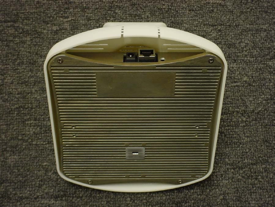
J26500003
Mar 29, 2005CalAmp Corp. Directed AP
Equipment Class
DTS - Digital Transmission System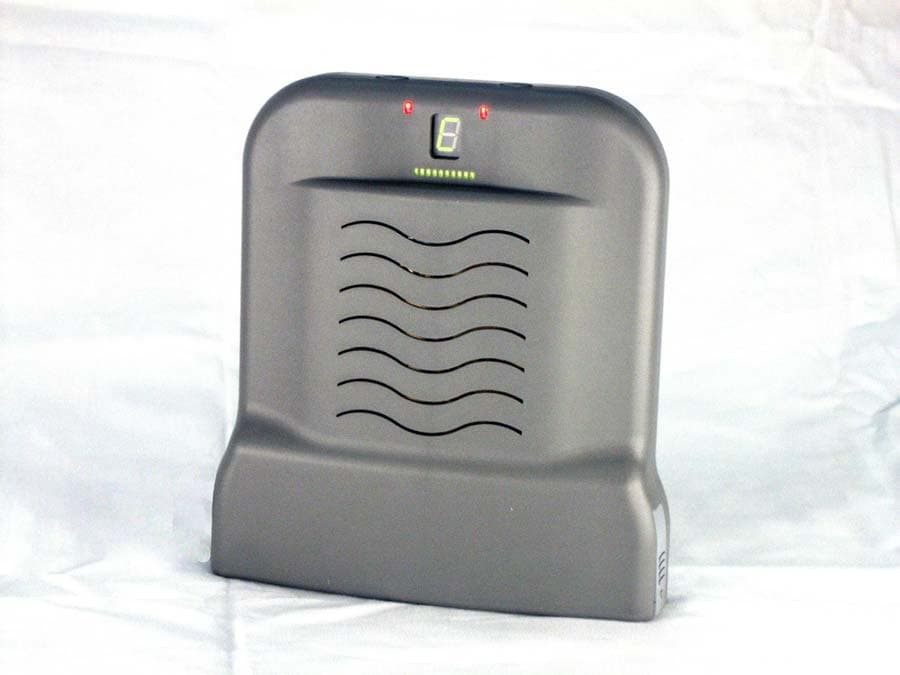
J26520038
Sep 03, 2003Ecco Mustang PCS Amplifier
Equipment Class
AMP - Amplifier
J26-530009
Mar 16, 2003MMDS Wireless Modem, 530009
Equipment Class
TNB - Licensed Non-Broadcast Station Transmitter
J26520031-2
Sep 30, 2001MMDS/MMDS Low TX In-Band Transceiver
Equipment Class
TNB - Licensed Non-Broadcast Station Transmitter